
AGCO Power EEM4 Troubleshooting Manual – Stage 4 Electronic Engine Management Fault Code & Diagnostic PDF
Original price was: $63.95.$39.95Current price is: $39.95.
Complete AGCO Power EEM4 Stage 4 Electronic Engine Management troubleshooting manual (Release 1.4, December 04, 2012). 199 pages of fault code diagnostics, sensor test data, ECU pinouts, SCR aftertreatment, EGR, injector harness and ECU replacement procedures for AGCO SISU POWER engines.
Description
AGCO Power EEM4 Troubleshooting Manual – Release 1.4
This is the complete AGCO Power EEM4 troubleshooting manual, published by AGCO POWER Inc on December 04, 2012. It covers the EEM4 Stage 4 Electronic Engine Management system used on AGCO SISU POWER engines, including the EDC17CV54 and EDC17CV41 engine control units. The manual is written for technicians, service personnel and fleet maintenance teams who need to read fault codes, trace electrical faults, test sensors and understand exactly how each component of the EEM4 system behaves when a fault is active. Every fault code entry is broken down into Description, Reaction in EEM and Solution, so you can move from a code number to a repair path without guessing.
File Details
- Manual Type: Troubleshooting Manual
- Brand / Publisher: AGCO Power (AGCO POWER Inc)
- System: EEM4 – AGCO SISU POWER Stage 4 Electronic Engine Management
- Language: English
- Page Count: 199 pages
- File Format: PDF
- Release: 1.4
- Publication Date: December 04, 2012
- ECU Platforms Covered: EDC17CV54, EDC17CV41
Chapters Covered
- 1 Introduction
- 2 EEM4 general instructions
- 3 Fault Codes
- 4 Sensor details
- 5 Aftertreatment
- 6 Engine electric system
- 7 ECU Replacement Procedure
1 Introduction
Purpose, scope and the definitions, terms, acronyms and abbreviations used across the whole EEM4 troubleshooting manual. Includes the Service Tool, CAN bus, FLn and SLn limitation-level terminology, MPROP, PRV and System Reset definitions that appear repeatedly in the fault code chapters.
2 EEM4 General Instructions
Safety warnings covering the high-pressure fuel system, including the high pressure pump, fuel lines to the common rail, rail itself, lines to the injectors, injectors and all attached sensors and valves. Covers electric welding precautions, high pressure washing precautions, and the correct handling of EEM4 controllers, sensors and connectors during vehicle or engine service.
3 Fault Codes
The largest section of the manual: over 320 individual fault code entries, each with a Description of the fault, the Reaction in EEM (what the ECU does, including warning lamp, degradation level, fuel or speed limiting, and shutdown behaviour), and a Solution path covering mechanical checks and electrical checks. Fault coverage includes SPN 100 oil pressure (FMI 0, 1, 3, 4, 16, 18, 31), SPN 102 boost pressure (FMI 3, 4, 16, 18, 31), SPN 105 intake air temperature, SPN 107 air filter pressure, SPN 108 ambient pressure, SPN 109 coolant pressure, SPN 110 coolant temperature (FMI 0, 3, 4, 16), SPN 157 rail pressure (FMI 0, 2, 3, 4, 14, 15, 16, 17, 18, 20, 21, 31), SPN 168 battery voltage, SPN 171 ambient temperature, SPN 174 fuel inlet temperature, SPN 190 engine speed, SPN 626/729 grid heater, SPN 639/520201 CAN bus off, SPN 651-657 solenoid valves / injectors, SPN 677/1321 start relay, SPN 723 camshaft speed, SPN 974 throttle 3, SPN 977 fan control, SPN 1043 internal 12V supply, SPN 1076/1077 MPROP control, SPN 1136 ECU over temperature, SPN 1381 fuel supply pump inlet pressure, SPN 1485 main relay, SPN 1639 fan speed, SPN 1761 DEF tank level, SPN 2659/2791 EGR, SPN 3031 DEF tank temperature, SPN 3349 TSC1 timeout, SPN 3361/3363 DEF dosing and tank heater, SPN 3509-3512 sensor supply voltages, SPN 4090 SCR NOx, SPN 4201 crankshaft speed sensor, SPN 4332/4334/4340/4342/4344/4346 SCR and DEF heater circuits, SPN 4360/4363 SCR catalyst temperature sensors, SPN 4374/4375/4376 DEF pump, SPN 4792 SCR catalyst, SPN 5020 EGR mixer intake temperature, SPN 520200-520298 ECU internal faults and rail PRV monitoring, SPN 521000-521010 DEF pump and heater diagnostics.
4 Sensor Details
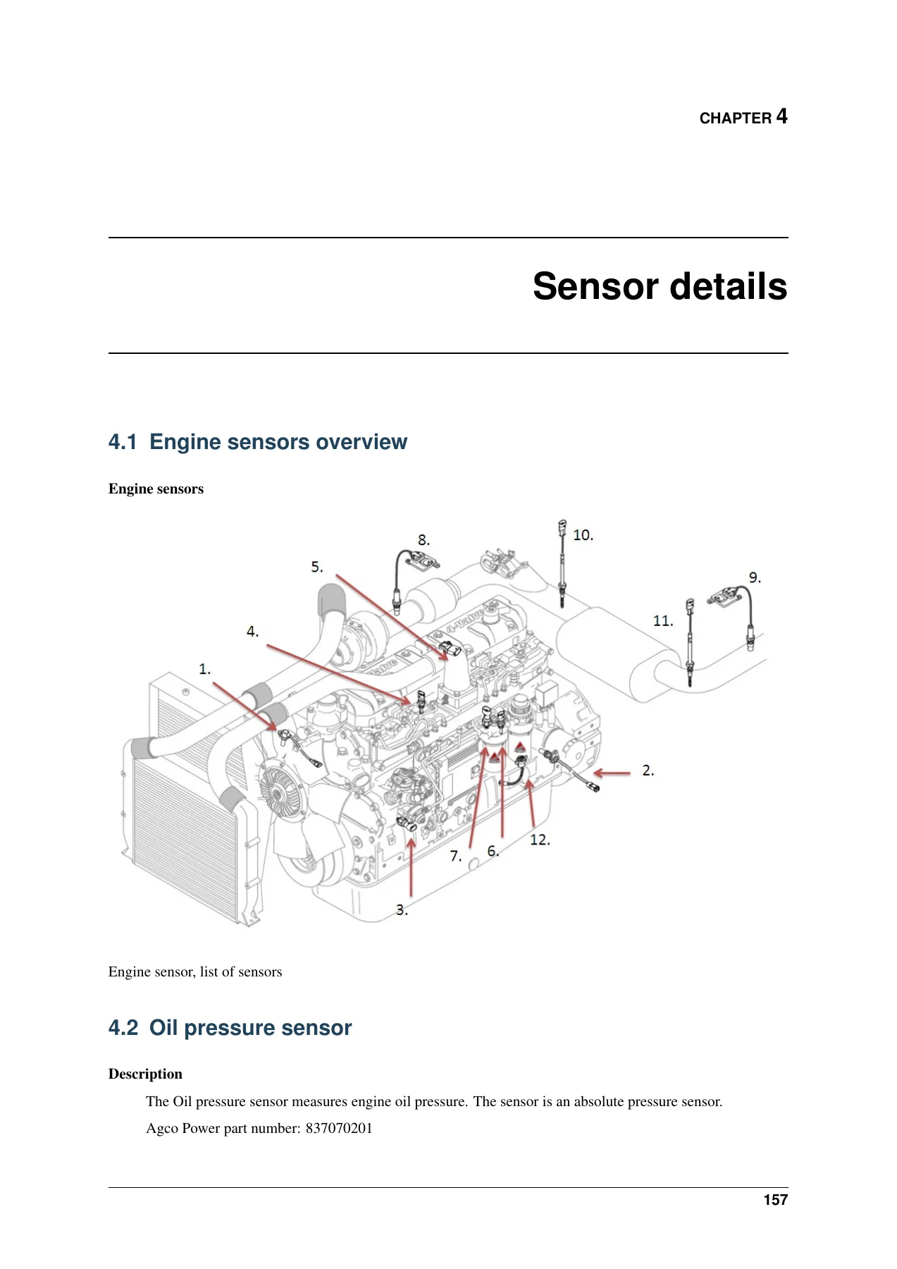
Component-level detail for every major engine sensor in the EEM4 system. Each sensor entry gives the AGCO Power part number, ECU connection pin numbers for both EDC17CV54 and EDC17CV41, connector pinout illustrations, and characteristic curves or resistance tables. Sensors covered: engine sensors overview illustration, oil pressure sensor (837070201), coolant temperature sensor (836667732), fuel pressure sensor (837070201), fuel temperature sensor (836667732), crankshaft speed sensor (837069150), camshaft speed sensor (836667732), NOx sensor (837073768), exhaust gas temperature sensor (837074294), boost pressure sensor (837073934), intake air temperature sensor (837073934), rail pressure sensor (837079434), coolant pressure sensor (837070201), water in fuel sensor (837074054), fuel supply pump inlet pressure sensor (837070209) and engine EGR mixer intake temperature sensor (837074507).
5 Aftertreatment
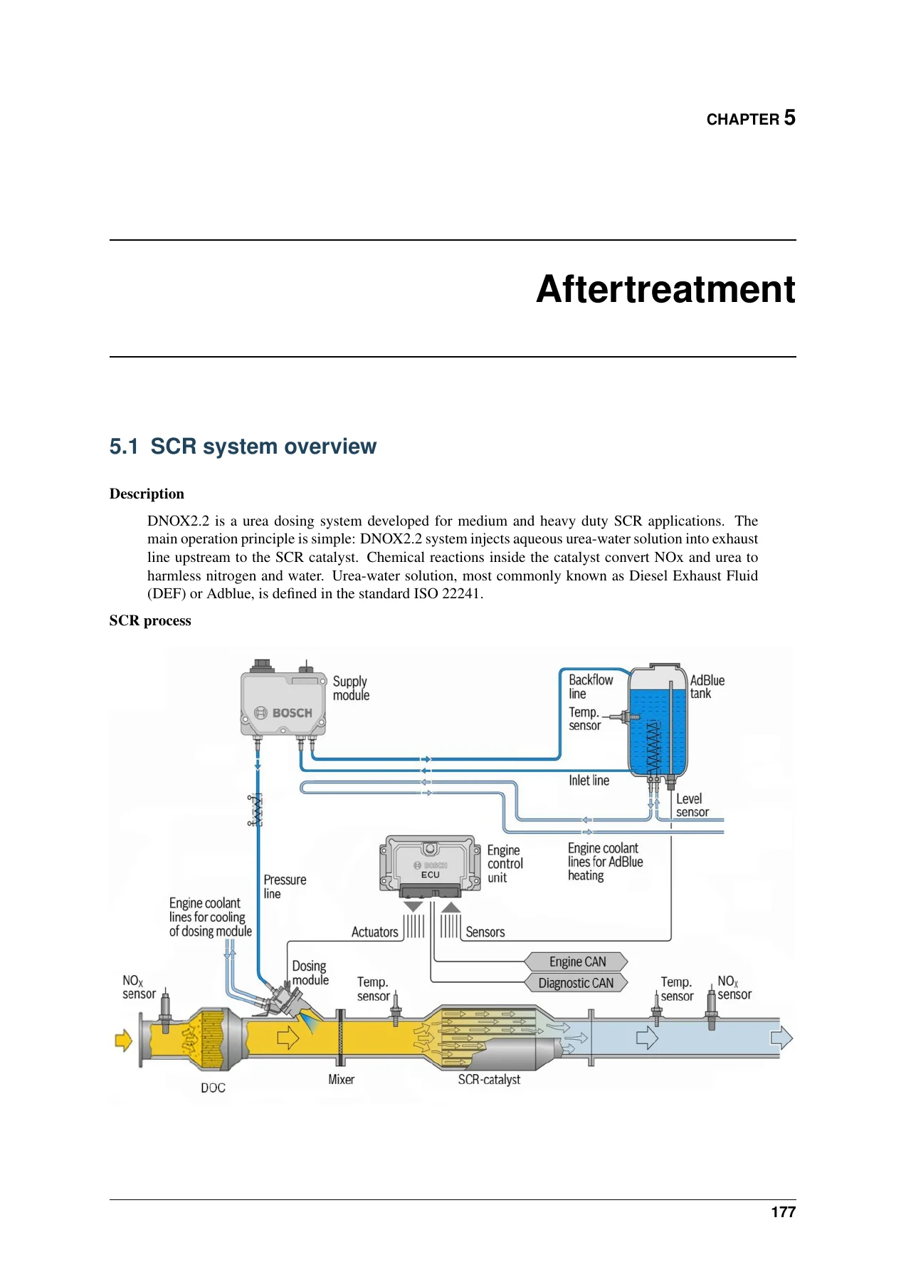
The SCR system overview (DNOX2.2 urea dosing system), including the full SCR process diagram showing supply module, AdBlue tank, backflow line, inlet line, pressure line, dosing module, DOC, mixer, SCR catalyst, temperature sensors and NOx sensors. Covers the supply module (837073770 12V / 837073771 24V) with its 12-pin connector assignment, normal operating pressure (8-10 bar), pressure build-up time (approx. 2-4 minutes) and emptying time (approx. 2 minutes), the dosing module (837073772) with valve resistance and operating voltage, and the external EGR actuator (837074614) used on AGCO Power 3-cylinder engines.
6 Engine Electric System
Electrical system reference material for the EEM4 platform. Includes grid heater solenoid connections (A60 high side, A34 low side), start relay, 4-cylinder engine injector harness, 6-cylinder engine injector harness, 7-cylinder engine injector harness with cylinder-to-solenoid-valve mapping (cylinders 1-7 mapped to solenoid valves 1, 2, 7, 3, 6, 4, 5), and the engine ECU power supply and ground connection diagram.
7 ECU Replacement Procedure
Step-by-step guidance for replacing the EEM4 controller. Includes the warning to open the vehicle main switch or disconnect battery terminals before connecting or disconnecting the large 94-pin or 96-pin ECU vehicle connector, the note on engine S/N mismatch when fitting a controller from another tractor, and the requirement to update software and activate the ECU with an activation code requested from AGCO SISU POWER to avoid fault code SPN 520230, FMI 31, Engine specification mismatch.
Why This AGCO Power EEM4 Troubleshooting Manual Matters
The EEM4 system manages fuel injection, rail pressure, boost, EGR, SCR dosing and aftertreatment on AGCO SISU POWER Stage 4 engines. When a fault code appears, the difference between a quick repair and an expensive parts-swapping session is knowing exactly what the ECU has detected, what the system does in response, and which electrical or mechanical checks to run first. This manual gives you that path for every fault code the EEM4 system can set, from a simple oil pressure sensor voltage fault through to complex SCR dosing quantity balance errors and internal ECU faults.
Because every fault entry is split into Description, Reaction in EEM and Solution, you can see whether a code causes a warning lamp only, a degradation level, a fuel or speed limit, or an engine shutdown after 30 seconds. That lets you prioritise diagnosis correctly, and it lets you explain to the machine owner why the engine is derating or shutting down. The sensor chapter then gives you the exact ECU pin numbers, connector views and resistance or voltage values so you can confirm a sensor fault with a meter before replacing anything.
Who This Manual Is For
This AGCO Power EEM4 troubleshooting manual is aimed at diesel technicians, agricultural and heavy equipment mechanics, fleet maintenance departments, and anyone responsible for diagnosing or repairing AGCO SISU POWER engines fitted with the EEM4 Stage 4 engine management system. It is equally useful for service managers who need to understand what a fault code means before authorising a repair, and for technical trainers building diagnostic courses around the EEM4 platform.
Get Instant Access
IMAGES PREVIEW
This AGCO Power EEM4 Stage 4 Electronic Engine Management troubleshooting manual is delivered as an instant PDF download, with no shipping and no waiting. Once payment is complete you can open it on a laptop, tablet or phone, search the fault code you need, and print the pages you want for the workshop. The 199-page Release 1.4 document gives you the full fault code library, sensor test data, SCR and EGR diagnostics, injector harness layouts and ECU replacement procedure in one file – so the next time an EEM4 fault code appears, you already have the answer in front of you.
Reviews
There are no reviews yet.