
★ TRUSTED BY 321,897+ PROFESSIONALS WORLDWIDE
🏢
Trusted Business
Verified & Licensed
🛡️
Virus Free Files
100% Safe Downloads
🔒
Secure Payment
SSL Protected
Instant Delivery
Available Immediately
Sale!

Airbus A318 A319 A320 A321 Windshield Frame Service Bulletin A320-53-1329 – PDF

Original price was: $24.95.Current price is: $14.95.

Official Airbus Service Bulletin A320-53-1329 (Rev.00, Dec 21/18) covering replacement of the frontal windshield frames and Y0 continuity fittings on A318/A319/A320/A321 aircraft. Full 351-page accomplishment instructions in instant PDF download.

Instant PDF Download
Available immediately
💾
Save to Your Device
Download & keep forever
🛡️
Antivirus Scanned
100% virus-free
🌍
Trusted Worldwide
175,000+ customers

Description

Airbus A320-53-1329 Windshield Frame Service Bulletin – A318/A319/A320/A321

This is the complete Airbus Service Bulletin A320-53-1329 (Revision 00, dated Dec 21/18), titled “Fuselage – Main Structure – Modify Windshield Center Post Lower Area with Titanium Upper Skin Panel,” covering the A318, A319, A320 and A321 aircraft family. This Windshield Frame Service Bulletin lays out the full engineering justification, material kits, tooling, and step-by-step accomplishment instructions used by operators to replace the frontal windshield frames and center node continuity fittings.

  • Manual type: Airbus Service Bulletin (ATA 53 – Fuselage)
  • Bulletin number: A320-53-1329, Revision 00 – Dec 21/18
  • Aircraft: Airbus A318, A319, A320, A321 family
  • Modification number: 158558P15297
  • Language: English
  • Page count: 351 pages
  • File format: PDF

Why This Service Bulletin A320-53-1329 Was Issued

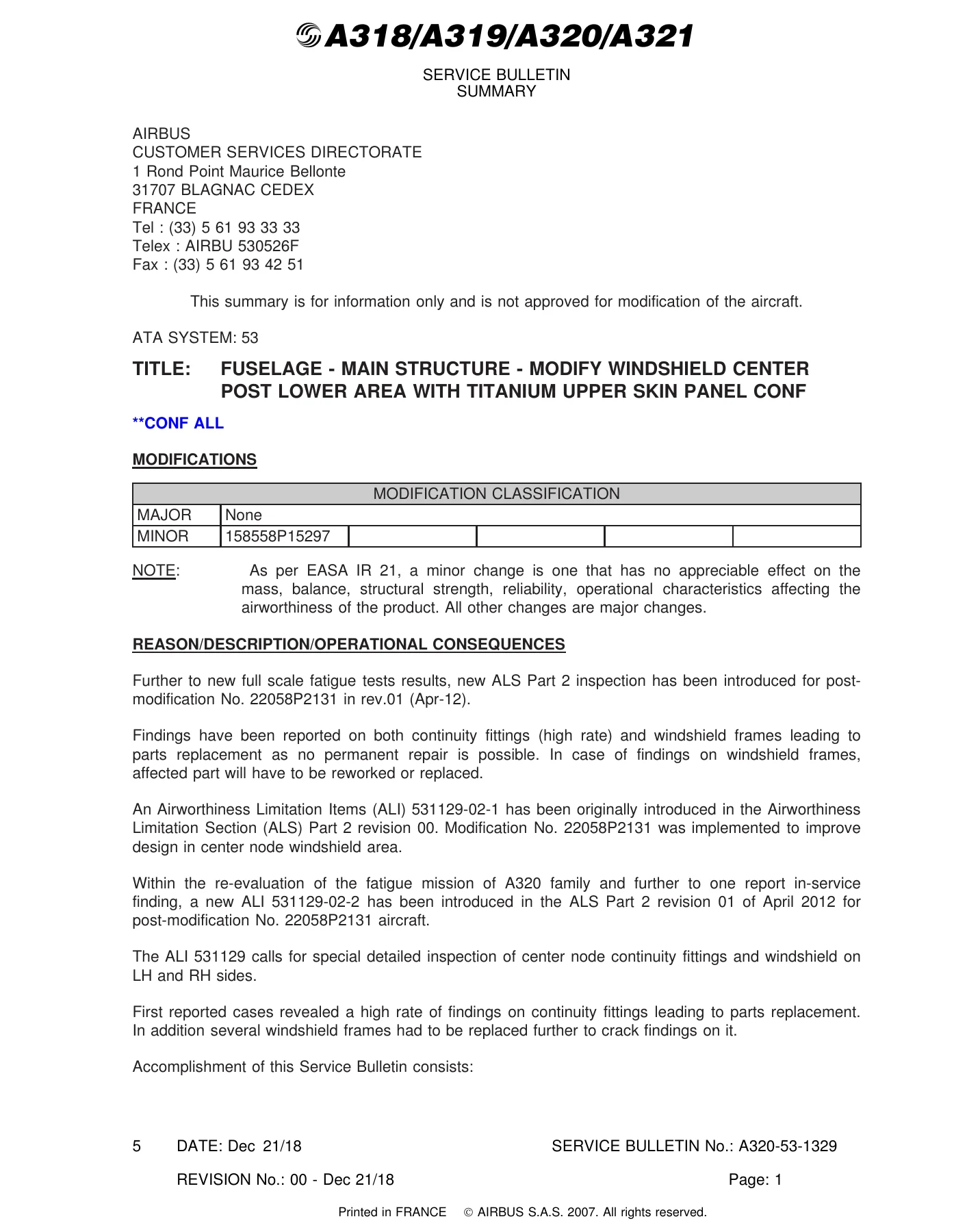
Following full-scale fatigue test results, Airbus introduced a new ALS Part 2 inspection (ALI 531129) covering the center node continuity fittings and windshield frames on both LH and RH sides. In-service findings showed a high rate of cracking on continuity fittings and windshield frames, with no permanent repair possible in many cases – meaning affected parts required outright replacement. This A320-53-1329 bulletin was written to give operators a permanent engineering fix rather than a repeating inspection cycle.

What the A320-53-1329 Modification Covers

Accomplishment of this Service Bulletin consists of replacing the windshield frames on both LH and RH sides with new reinforced, shot-peened frames that reposition two 6.7 mm (0.26 in.) fasteners, including the associated spot-facing deletion on the left and right front window frame, and installing new shot-peened continuity fittings. Once embodied, this modification is stated to prevent cracking on the frontal windshield frame and continuity fitting, and – if embodied after 29,400 flight cycles – cancels the requirements of the related Inspection Service Bulletin A320-53-1331.

IMAGES PREVIEW

Airbus A318 A319 A320 A321 Windshield Frame Service Bulletin A320-53-1329 - PDF — PDF page 1 preview
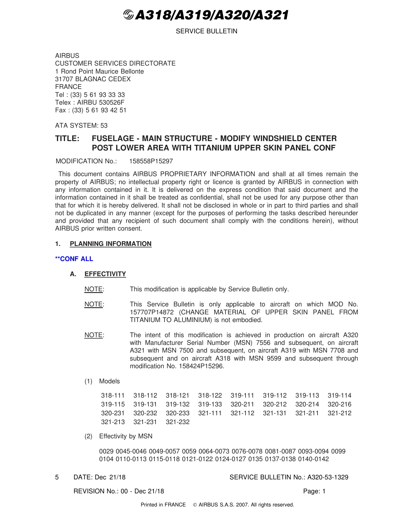
Airbus A318 A319 A320 A321 Windshield Frame Service Bulletin A320-53-1329 - PDF — PDF page 7 preview
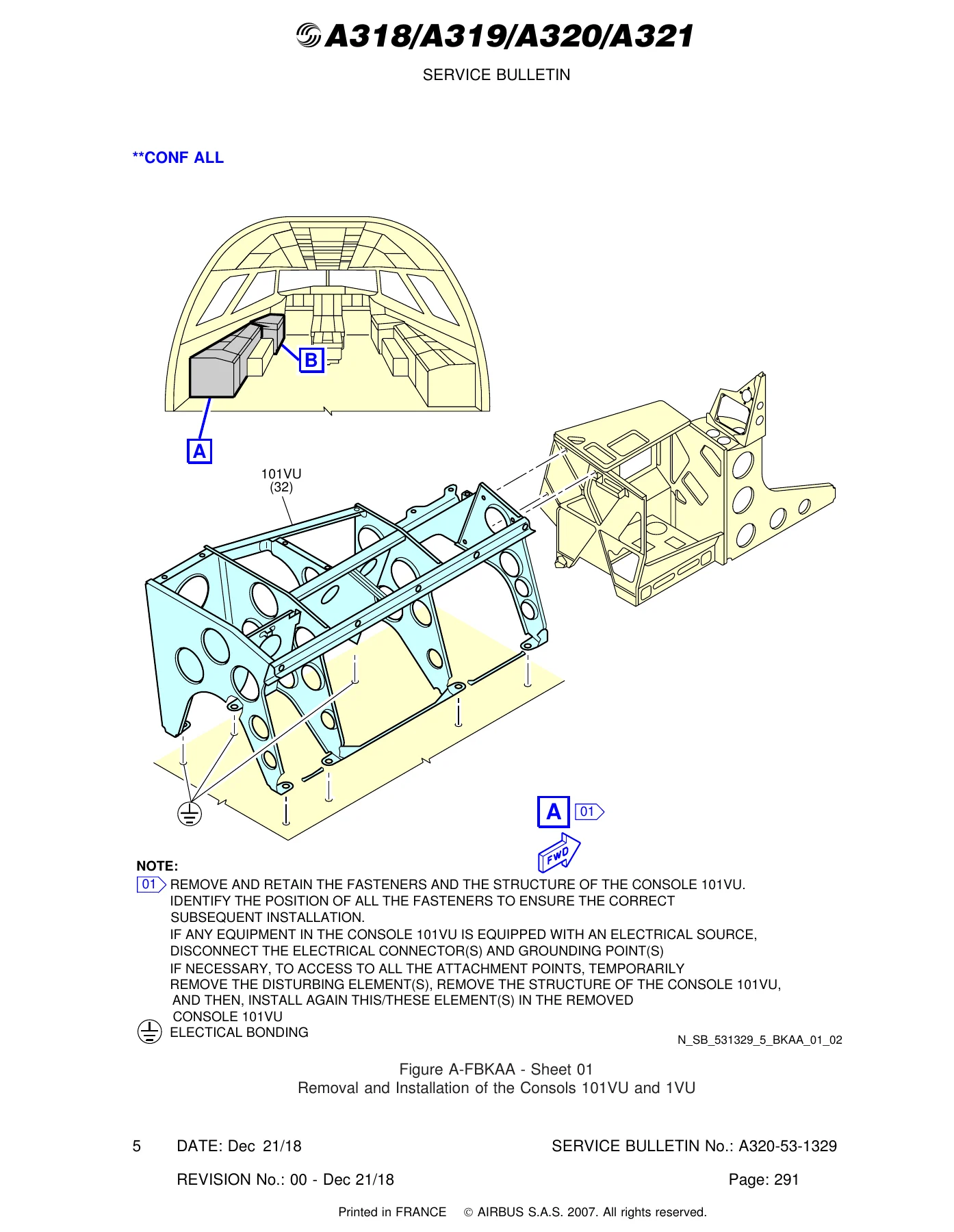
Airbus A318 A319 A320 A321 Windshield Frame Service Bulletin A320-53-1329 - PDF — PDF page 297 preview

Chapters Covered

  • 1. Planning Information
    • A. Effectivity (Models & MSN ranges)
    • B. Concurrent Requirements
    • C. Reason (History, Objective/Action, Advantages, Operational Consequences)
    • D. Description (37-step task breakdown)
    • E. Compliance
    • F. Approval (EASA.21J.031)
    • G. Manpower
    • H. Weight and Balance
    • I. Electrical Load Data
    • J. References (AMM, ESPM, SRM, ISI, Repair Instructions)
    • K. Publication Affected (IPC)
    • L. Interchangeability/Mixability
    • M. Spares
  • 2. Material Information
    • A. Material Price and Availability
    • B. Industry Support Information
    • C. List of Components (Kits 531329A01R00 through A07R01)
    • D. List of Materials – Operator Supplied
    • E. Parts to Be Re-Identified by Operator
    • F. Tooling
  • 3. Accomplishment Instructions – Task 531329-831-801-001
    • A. General
    • B. Preparation
    • C. Procedure (Steps 1-37: cockpit and avionics access, panel removal, window frame and continuity fitting replacement, reassembly)
    • D. Test
    • E. Close-Up
  • Appendices
    • Appendix 01 – Glossary
    • Appendix 02 – Manpower Gantt Chart
    • Appendix 03 – Panels to Remove and Install for Access
    • Appendix 04 – Window Frames Assembly to Replace

Complete PDF Bookmark Tree

Complete Bookmarks

The complete bookmarks in the “Airbus A318 A319 A320 A321 Windshield Frame Service Bulletin A320-53-1329 – PDF” are as follows:

SUMMARYp. 1
Figure A-FSAAA –p. 6
Sheet 01p. 6
PLANNING INFORMATIONp. 7
EFFECTIVITYp. 7
CONCURRENT REQUIREMENTSp. 41
REASONp. 41
DESCRIPTIONp. 42
COMPLIANCEp. 45
APPROVALp. 45
MANPOWERp. 46
WEIGHT AND BALANCEp. 49
ELECTRICAL LOAD DATAp. 49
REFERENCESp. 49
PUBLICATION AFFECTEDp. 52
INTERCHANGEABILITY/MIXABILITYp. 52
SPARESp. 52
MATERIAL INFORMATIONp. 53
MATERIAL – PRICE AND AVAILABILITYp. 53
INDUSTRY SUPPORT INFORMATIONp. 55
LIST OF COMPONENTSp. 55
LIST OF MATERIALS – OPERATOR SUPPLIEDp. 60
PARTS TO BE RE-IDENTIFIED BY OPERATORp. 63
TOOLINGp. 63
ACCOMPLISHMENT INSTRUCTIONSp. 67
Replacement of the Frontal Window Framesp. 67
GENERALp. 68
CONF 001p. 68
Standard Practicesp. 68
Administrativep. 71
CONF 002p. 71
Standard Practicesp. 71
Administrativep. 74
PREPARATIONp. 74
CONF 001p. 74
Job Set-upp. 74
CONF 002p. 76
Job Set-upp. 76
PROCEDUREp. 78
CONF 001p. 78
Remove the Items of Equipment from the Cockpit for Accessp. 78
Remove the Lateral VUs and the Stowage from the Cockpit for Access, LH sidep. 84
Remove the Lateral VUs and the Stowage from the Cockpit for Access, RH sidep. 86
Remove the Main Instrument Panel 10VUp. 88
Remove the Overhead Panel 20VUp. 91
Remove the Remaining Items from Cockpit for Accessp. 94
Remove the Items of Equipment from the Avionics Compartment for Accessp. 96
Remove the Harnesses and the Insulation Blankets from the Working Areap. 98
Remove the LH Lateral Panel for Accessp. 99
Remove the RH Lateral Panel for accessp. 99
Remove the Crown Panels for accessp. 100
Remove the FWD Skin Panel and the False Frame for Accessp. 101
Remove the Y0 Continuity Fittingp. 102
Remove the Front to LH Lateral Window Frames Junctionp. 103
Remove the Front to RH Lateral Window Frames Junctionp. 105
Remove the LH Crown Stiffeners and the Fittings and Brackets from the LH Front Window Framep. 106
Remove the RH Crown Stiffeners and the Fittings and Brackets from the RH Front Window Framep. 108
Remove the Front Window Frames assemblyp. 109
On Bench, Modify the New Front Window Frames assemblyp. 110
Put in Position the New Window Frames Assemblyp. 111
Install the Front Window Frames assemblyp. 117
Install the Front to LH Lateral Window Frames Junctionp. 120
Install the Front to RH Lateral Window Frames Junctionp. 125
Install the Y0 Continuity Fittingsp. 130
Install the FWD Skin Panel and the False Framep. 134
Install the Crown Panelsp. 136
Install the LH Lateral Panelp. 139
Install the RH Lateral Panelp. 143
Renew the Surface Protection of the Modification Areap. 148
Install the Harnesses and the Insulation Blankets in the Working Areap. 149
Install the Items of Equipment in the Avionics Compartmentp. 150
Install the Remaining Items in the Cockpitp. 152
Install the Overhead Panel 20VUp. 153
Install the Main Instrument Panel 10VUp. 156
Install the Lateral VUs and the Stowage in the Cockpit, RH sidep. 158
Install the Lateral VUs and the Stowage in the Cockpit, LH sidep. 160
Install the items of Equipment in the Cockpitp. 162
CONF 002p. 168
Remove the Items of Equipment from the Cockpit for Accessp. 168
Remove the Lateral VUs and the Stowage from the Cockpit for Access, LH sidep. 174
Remove the Lateral VUs and the Stowage from the Cockpit for Access, RH sidep. 176
Remove the Main Instrument Panel 10VUp. 179
Remove the Overhead Panel 20VUp. 181
Remove the Remaining Items from Cockpit for Accessp. 184
Remove the Items of Equipment from the Avionics Compartment for Accessp. 186
Remove the Harnesses and the Insulation Blankets from the Working Areap. 188
Remove the LH Lateral Panel for Accessp. 189
Remove the RH Lateral Panel for accessp. 189
Remove the Crown Panels for accessp. 190
Remove the FWD Skin Panel and the False Frame for Accessp. 191
Remove the Y0 Continuity Fittingp. 192
Remove the Front to LH Lateral Window Frames Junctionp. 193
Remove the Front to RH Lateral Window Frames Junctionp. 195
Remove the LH Crown Stiffeners and the Fittings and Brackets from the LH Front Window Framep. 196
Remove the RH Crown Stiffeners and the Fittings and Brackets from the RH Front Window Framep. 198
Remove the Front Window Frames assemblyp. 199
On Bench, Modify the New Front Window Frames assemblyp. 200
Put in Position the New Window Frames Assemblyp. 201
Install the Front Window Frames assemblyp. 207
Install the Front to LH Lateral Window Frames Junctionp. 210
Install the Front to RH Lateral Window Frames Junctionp. 215
Install the Y0 Continuity Fittingsp. 220
Install the FWD Skin Panel and the False Framep. 224
Install the Crown Panelsp. 226
Install the LH Lateral Panelp. 229
Install the RH Lateral Panelp. 233
Renew the Surface Protection of the Modification Areap. 238
Install the Harnesses and the Insulation Blankets in the Working Areap. 239
Install the Items of Equipment in the Avionics Compartmentp. 240
Install the Remaining Items in the Cockpitp. 242
Install the Overhead Panel 20VUp. 243
Install the Main Instrument Panel 10VUp. 246
Install the Lateral VUs and the Stowage in the Cockpit, RH sidep. 248
Install the Lateral VUs and the Stowage in the Cockpit, LH sidep. 250
Install the items of Equipment in the Cockpitp. 252
TESTp. 258
CONF 001p. 258
Test Preparationp. 258
Preliminary Testp. 259
Testp. 260
CONF 002p. 268
Test Preparationp. 268
Preliminary Testp. 268
Testp. 269
CLOSE-UPp. 277
CONF 001p. 277
Close-upp. 277
CONF 002p. 278
Close-upp. 278
Figure A-FBAAA – Removal and Installation of the Hand Microphones and Boomsetsp. 280
Sheet 01p. 280
Sheet 02p. 281
Figure A-FBBAA – Removal and Installation of the Extinguishers and their Supportsp. 282
Sheet 01p. 282
Sheet 02p. 283
Sheet 03p. 284
Figure A-FBCAA – Removal and Installation of the Flashlightsp. 285
Sheet 01p. 285
Sheet 02p. 286
Figure A-FBDAA – Removal and Installation of the Various Equipmentsp. 287
Sheet 01p. 287
Sheet 02p. 288
Sheet 03p. 289
Sheet 04p. 290
Figure A-FBEAA – Removal and Installation of the Masks Oxygen and Adapers Oxygen and Cylinder Assy Portable Oxygenp. 291
Sheet 01p. 291
Sheet 02p. 292
Figure A-FBFAA – Removal and Installation of the EFB and LDSp. 293
Sheet 01p. 293
Figure A-FBGAA – Removal and Installation of the ELTp. 294
Sheet 01p. 294
Figure A-FBHAA – Removal and Installation of the Megaphonep. 295
Sheet 01p. 295
Figure A-FBJAA – Removal and Installation of the Protection Panelsp. 296
Sheet 01p. 296
Figure A-FBKAA – Removal and Installation of the Consols 101VU and 1VUp. 297
Sheet 01p. 297
Sheet 02p. 298
Figure A-FBLAA – Removal and Installation of the Consol 704VUp. 299
Sheet 01p. 299
Figure A-FBMAA – Removal and Installation of the Consol 702VU, 700VU and 7VUp. 300
Sheet 01p. 300
Sheet 02p. 301
Sheet 03p. 302
Figure A-FBNAA – Removal and Installation of the Panels 619VU and 620VUp. 303
Sheet 01p. 303
Figure A-FBOAA – Removal and Installation of the Covers from 10VUp. 304
Sheet 01p. 304
Figure A-FBPAA – Removal and Installation of the Panels 301VU, 401VU, 400VU, 500VU, 130VU and 131VUp. 305
Sheet 01p. 305
Sheet 02p. 306
Figure A-FBQAA – Removal and Installation of the Structure from 10VUp. 307
Sheet 01p. 307
Figure A-FBRAA – Removal and Installation of the Equipments and VUs from the overhead 20VUp. 308
Sheet 01p. 308
Figure A-FBSAA – Removal and Installation of the Blanking Pates from the Overhead 20VUp. 309
Sheet 01p. 309
Sheet 02p. 310
Figure A-FBTAA – Removal and Installation of the Structure 20VUp. 311
Sheet 01p. 311
Figure A-FBUAA – Removal and Installation of the Bracket of Controller Lightingp. 312
Sheet 01p. 312
Figure A-FBVAA – Removal and Installation of the 619VU and 620VUp. 313
Sheet 01p. 313
Figure A-FBWAA – Removal and Installation of the Air-Conditioningp. 314
Sheet 01p. 314
Sheet 02p. 315
Sheet 03p. 316
Figure A-FBXAA – Removal and Installation of the Plate from 20VUp. 317
Sheet 01p. 317
Sheet 02p. 318
Figure A-FBYAA – Removal and Installation of the Plumbing Standby Systemsp. 319
Sheet 01p. 319
Figure A-FBZAA – Removal and Installation of the Rain-Repellant Plumbingp. 320
Sheet 01p. 320
Figure A-FCAAA – Removal and Installation of the Drains from Cockpitp. 321
Sheet 01p. 321
Sheet 02p. 322
Sheet 03p. 323
Sheet 04p. 324
Figure A-FCBAA – Removal and Installation of the Brackets from Window Frames Assembly at Y0p. 325
Sheet 01p. 325
Sheet 02p. 326
Sheet 03p. 327
Figure A-FCCAA – Removal and Installation of the Plates from PHC and WHCp. 328
Sheet 01p. 328
Sheet 02p. 329
Figure A-FCDAA – Removal and Installation of the 109VUp. 330
Sheet 01p. 330
Figure A-FCFAA – Installation of the Rudder Control Rigging-Pinp. 331
Sheet 01p. 331
Figure A-FCGAA – Removal and Installation of the Cover and Flanges from Pedalsp. 332
Sheet 01p. 332
Sheet 02p. 333
Figure A-FCHAA – Removal and Installation of the Brackets from the Window Frames at Y0p. 334
Sheet 01p. 334
Figure A-FCJAA – Removal and Installation of the Panel 62VU and the Panelp. 335
Sheet 01p. 335
Appendix 01 – Glossaryp. 337
Appendix 02 – Manpower Gantt Chartp. 339
Figure A-FAAAA – Appendix 02 – Manpower Gantt Chartp. 340
Sheet 01p. 340
Sheet 02p. 341
Sheet 03p. 342
Appendix 03 – Panels to Remove and Install for Accessp. 343
Figure A-FABAA – Panels to Remove and Install for Accessp. 344
Sheet 01p. 344
Sheet 02p. 345
Appendix 04 – Window Frames Assembly to Replacep. 347
Figure A-FACAA – Window Frames Assembly to Replacep. 348
Sheet 01p. 348
Sheet 02p. 349
Service Bulletin REPORTINGp. 350
QUALITY PERCEPTION FORMp. 351

Taken together, this Service Bulletin gives an A320-family maintenance team the complete picture: why the windshield frame and continuity fitting modification exists, which aircraft it applies to, what kits and tools are needed, and exactly how the 37-step removal-and-installation task is performed from initial cockpit access through final close-up and return-to-service testing.

Get the A320-53-1329 Service Bulletin Now

This Airbus A320-53-1329 Windshield Frame Service Bulletin equips planning engineers and maintenance crews to scope, quote, and execute the frontal windshield frame and continuity fitting replacement on eligible A318/A319/A320/A321 aircraft – including manpower estimates (1122.00 total manhours / 333.0 elapsed hours), material kit part numbers, and the full on-aircraft procedure. Having the original Airbus reference on hand means the job is planned and performed to the documented standard rather than reconstructed from memory. This is an instant PDF download – no shipping, available immediately after purchase, viewable on any computer, tablet or phone, and fully printable for hangar use.

Reviews

There are no reviews yet.

Be the first to review “Airbus A318 A319 A320 A321 Windshield Frame Service Bulletin A320-53-1329 – PDF”

What Our Customers Say

★★★★★ Live reviews from customers
Loading customer reviews...
0
    0
    Your Cart
    Your cart is emptyReturn to Shop
    🛒
    Recently Purchased
    🕒 verified order