Aloka SSD-500 Service Manual PDF Instant Download
Original price was: $95.00.$18.95Current price is: $18.95.
Download the comprehensive Aloka SSD-500 service manual PDF for expert ultrasound repair and maintenance. This SSD-500 ultrasound troubleshooting guide includes schematic diagrams, block diagrams, disassembly procedures, and parts lists for the Aloka echo camera repair manual. Ideal for technicians handling SSD-500 schematic diagrams PDF and ultrasound maintenance on SSD-500 models. Get instant access to this Aloka SSD-500 parts list and service resource.
Description
Aloka SSD-500 Service Manual PDF Download
Description
The Aloka SSD-500 Service Manual PDF Download is an essential resource for servicing and repairing the Aloka Echo Camera SSD-500 ultrasound system. This detailed Aloka SSD-500 service manual download provides in-depth guidance on troubleshooting, adjustments, and maintenance, making it a must-have SSD-500 ultrasound troubleshooting guide for medical equipment technicians. Covering everything from system block diagrams to schematic diagrams, this Aloka echo camera repair manual ensures you can efficiently diagnose and fix issues with the SSD-500 model.
File Details:
- Manual Name: Service Manual for Echo Camera SSD-500 (English Version)
- Models Covered: SSD-500
- Year: 1989
- Manual PDF Quality: High-quality scanned document
- No. of Pages: 249
The manual is structured into sections for easy navigation, focusing on practical repair strategies like picking out faulty PCBs and replacing them. It incorporates surface mount technology (S.M.T.) details and emphasizes safety precautions. Below is the neatly categorized Table of Contents extracted from the manual, formatted for clarity:
- Section 1: Introduction
- 1-1 Service Manual
- 1-2 Best Use of Service Manual
- 1-3 Contents of This Service Manual
- 1-4 Construction of This Service Manual
- 1-5 Contents of Each Section
- Section 2: Precaution (Please Read Without Fail)
- 2-1 Precautions Against Electrical Hazards to Serviceman
- 2-2 Precautions Against Mechanical Hazards to Serviceman
- 2-3 Precautions Against Germ Hazards to Serviceman
- 2-4 Precautions for Keeping Electrical Safety of SSD-500
- 2-5 Precautions for Keeping Mechanical Safety of SSD-500
- 2-6 Precautions for Keeping Chemicals Safety of SSD-500
- 2-7 Preparation to Be Made at Service Center
- 2-8 Care to Be Taken in the Field
- Section 3: Before Repairing
- 3-1 Handling of S.M.T. and S.M.D.
- Section 4: Disassembling Procedure
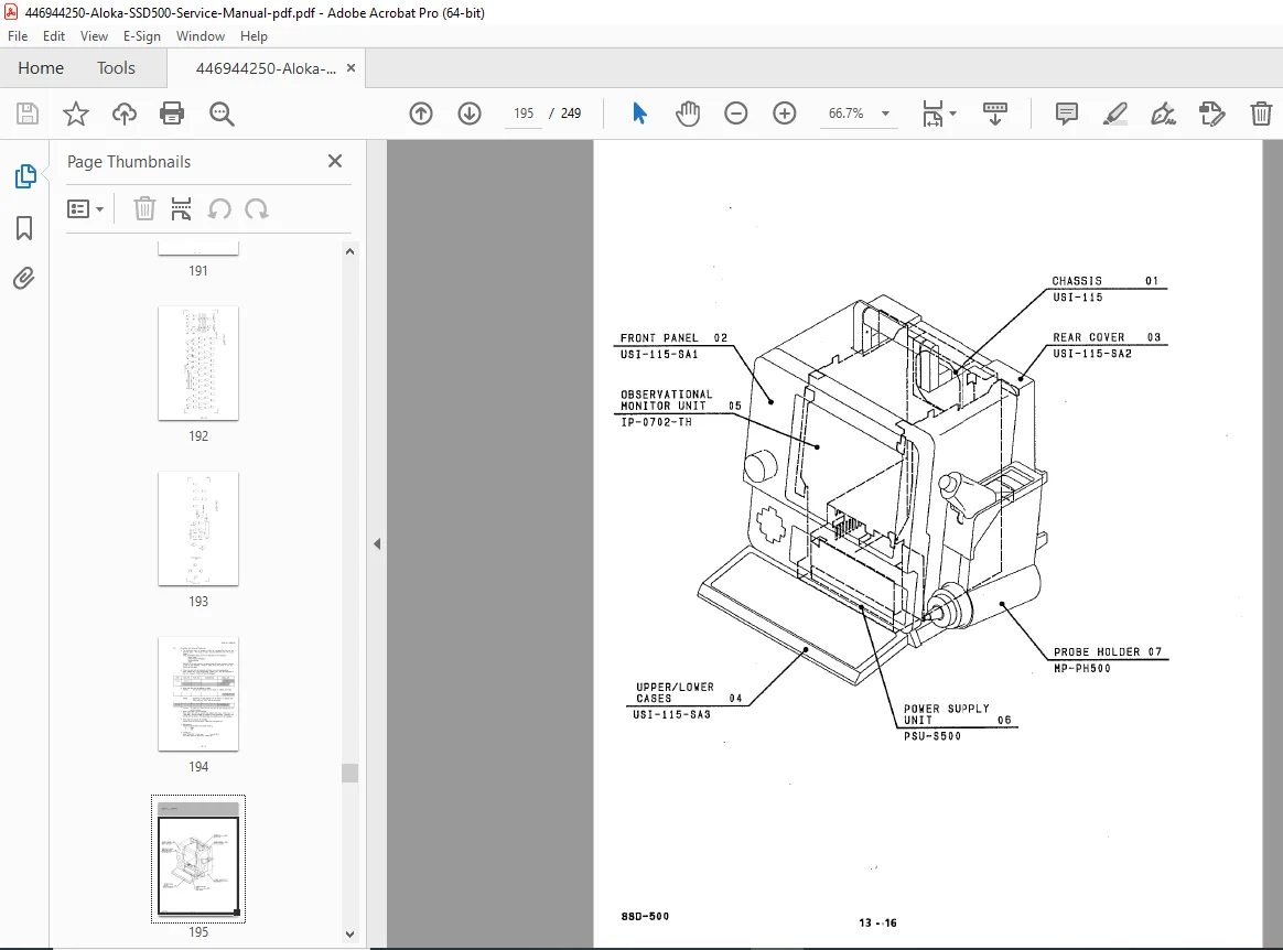
- 4-1 Disassembling Procedure of the Main Body
- Section 5: System Block Diagram
- 5-1 Explanation of System
- 5-2 System Block Diagram
- Section 6: PCB Block Diagram
- 6-1 Introduction
- 6-2 Panel Control EP-2873
- 6-3 Rx EP-2868
- 6-4 Tx & Control EP-2869
- 6-5 ITF EP-2870
- 6-6 DSC EP-2871
- 6-7 MPU EP-2872
- 6-8 Panel Board L-KEY-14 A, B
- 6-9 Gain & Power LED EP-2878
- 6-10 Select Key EP-2879
- 6-11 Contrast & Brightness EP-2880
- 6-12 In / Out EP-2881
- 6-13 Photo Cont. / Bright. EP-2882
- Section 7: Schematic Diagram
Item Board Page Synthetical Schematic of USI-115 7-1 Gain & Power LED EP-2878 7-2 Select Key EP-2879 7-3 In / Out EP-2881 7-4 L-KEY-14 A 7-5 L-KEY-14 B 7-6 EP-2868 (Device Location) 7-10 EP-2869 (Device Location) 7-11 EP-2870 (Device Location) 7-12 EP-2871 (Device Location) 7-13 EP-2872 (Device Location) 7-15 EP-2873 (Device Location) 7-16 EP-2878 (Device Location) 7-18 EP-2879 (Device Location) 7-19 EP-2881 (Device Location) 7-20 EP-2882 (Device Location) 7-21 L-KEY-14 A (Device Location) 7-22 L-KEY-14 B (Device Location) 7-23 Cable List 7-24 Cable Connection of EP-2873 7-31 Power Supply Unit PSU-S500 7-33 TV Monitor IP-0702-TH 7-35 - Section 8: Trouble Shooting
- 8-1 Introduction
- 8-2 Attention
- 8-3 Tools and Measures
- 8-4 Using Method of Trouble Shooting
- 8-5 Information for Repairing
- 8-5-1 Automatic Setting Up
- 8-5-2 Condition of Switch on PCB
- 8-5-3 How to Use the User Function
- 8-5-4 Attention of Connecting Optional Units
- 8-5-5 How to Reset Backup RAM
- 8-5-6 Location of PCBs
- 8-5-7 Location of ROMs
- 8-5-8 Disposition of Locking Up
- 8-6 PCB (Check) List Map
- 8-6-1 Phenomenon Code Table
- 8-6-2 MAP
- 8-7 Wave Form Diagram
- 8-7-1 Introduction
- 8-7-2 Attention
- 8-7-3 Rx EP-2868
- 8-7-4 Tx & Control EP-2869
- 8-7-5 ITF EP-2870
- 8-7-6 DSC EP-2871
- Section 9: Alignment Procedure
- 9-1 Introduction
- 9-2 Attention
- 9-3 Tools and Measures
- 9-4 Alignment Procedure
- 9-4-1 EP-2868 Rx
- Section 10: Performance Check
- 10-1 Introduction
- 10-2 Attention
- 10-3 Performance Check
- 10-4 Check Sheet
- Section 11: Maintenance Information
- 11-1 Introduction
- 11-2 Attention
- 11-3 Technical Information
- 11-3-1 Explanation of “STATUS”
- 11-3-2 “Probe Group”
- 11-3-3 How to Change the TV Scanning Lines
- 11-3-4 How to Change the Obstetrical Measurement
- 11-3-5 How to Change the AC Input Voltage
- 11-4 Manual Change Information
- Section 12: History of Improvement
- Section 13: Parts List
- Device Location on PCB
- 13-1 Parts List
- Section 14: Outline of System
- 14-1 Design Policy
- 14-2 Construction of System
- Section 15: Principle of Operation (System)
- 15-1 Specification
- 15-2 Feature
- 15-2-1 Multi Coated Probe
- 15-2-2 Electric Linear Scanning
- 15-2-3 Electric Convex Scanning
- 15-3 System Explanation
- 15-3-1 System Explanation
- 15-3-2 Signal Flow of Receiving
- 15-3-3 Panel Information
- 15-3-4 Digital Scan Converter
- 15-3-5 Viewing Monitor
- 15-3-6 Power Supply Unit
This SSD-500 schematic diagrams PDF and Aloka SSD-500 parts list make ultrasound maintenance on SSD-500 straightforward, with waveform diagrams, alignment guides, and performance checks. No index is present in the provided excerpts, but the detailed TOC serves as a comprehensive navigation aid.
Unlock expert-level repairs today—download this Aloka SSD-500 service manual PDF instantly and get your ultrasound system back to peak performance without delays!