Aloka SSD-500 Service Manual: Repair, Schematics & PCB Layouts (MN20142)
Original price was: $85.00.$20.95Current price is: $20.95.
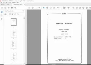
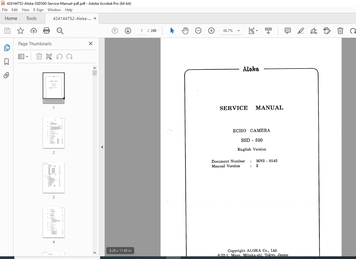
Comprehensive Aloka SSD-500 ultrasound service manual (Document MN20142) for biomedical technicians. This 200-page guide covers complete medical ultrasound disassembly procedures, system block diagrams, and deep-dive troubleshooting for boards including the EP-2871 DSC PCB. Includes full schematic diagrams, mechanical parts lists, and alignment protocols for maintaining the SSD-500 Echo Camera system.
Description
Aloka SSD-500 Service Manual: Repair, Schematics & PCB Layouts (MN20142) – PDF DOWNLOAD
Description
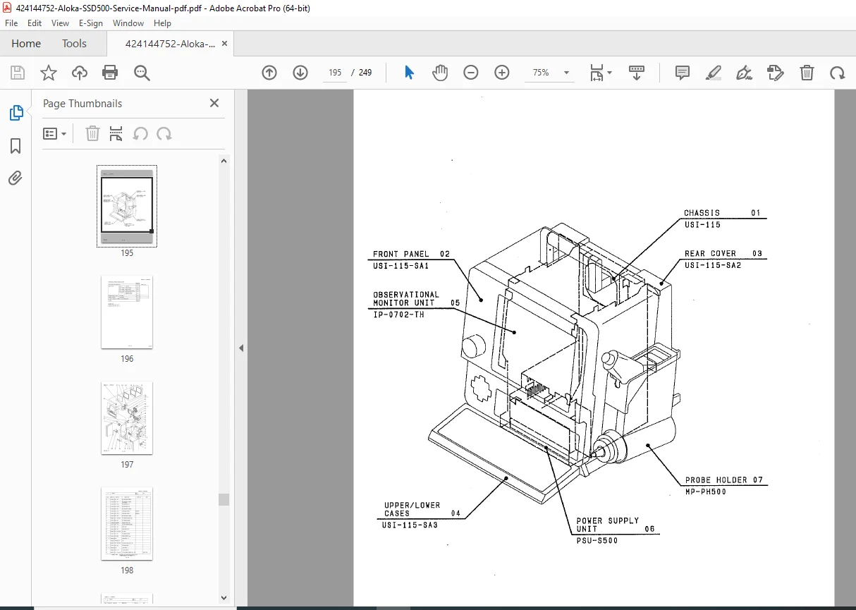
Unlock the ability to service, calibrate, and repair the Aloka SSD-500 Echo Camera with this official factory service manual. Essential for biomedical engineers and vintage medical equipment restorers, this document provides a granular look at the USI-115 system architecture.
This manual goes beyond basic operation, offering detailed Aloka SSD-500 ultrasound service manual instructions that guide you through the complex electronics of the device. Whether you are diagnosing a CRT issue on the IP-0702-TH monitor or performing a full medical ultrasound disassembly procedure, this PDF is the authoritative resource.
Key Technical Coverage:
The manual integrates vital PCB block diagram analysis for component-level repair. It specifically details the architecture of critical boards, including the Tx & Control (EP-2869), the Interface (EP-2870), and the Digital Scan Converter. If you are facing image artifacts or boot failures, the EP-2871 DSC PCB troubleshooting section and flowcharts will isolate the fault logic.
Comprehensive Table of Contents:
I. General Information & Safety
Section 1: Introduction & Manual Construction
Section 2: Precautions (Electrical, Mechanical, Biological/Germ Hazards)
Section 3: Before Repairing (Handling S.M.T. and S.M.D. components)
II. Disassembly & Hardware
Section 4: Medical Ultrasound Disassembly Procedure
Probe Holder & Connector Covers
CRT-PC Board (UPC-1610A) Pull-out
Power Supply Unit (PSU-S500) Removal
Control Panel (L-KEY-14 A/B) Dismounting
III. System Architecture & Electronics
Section 5: System Block Diagrams (Signal Flow)
Section 6: PCB Block Diagrams
Detailed analysis of: EP-2873 (Panel Control), EP-2868 (Rx), EP-2869 (Tx & Control), EP-2870 (ITF), EP-2872 (MPU), and EP-2880 (Contrast/Brightness).
IV. Schematics & Wiring
Section 7: SSD-500 Schematic Diagrams
Synthetical schematic of USI-115
Cable connection lists and PCB device locations
Power Supply Unit and TV Monitor schematics
V. Diagnostics & Calibration
Section 8: Trouble Shooting
Phenomenon Code Tables & Flowcharts
Waveform Diagrams for Rx, Tx, ITF, and DSC
Dip Switch Settings and ROM Locations
Section 9: Alignment Procedure
Section 10: Performance Check & Check Sheets
Section 11: Maintenance Information (Changing TV scanning lines, Voltage settings)
VI. Parts & Reference
Section 13: Parts List (Mechanical & Electrical)
Section 15: Principle of Operation (System & Hardware)
File Details
| Feature | Detail |
| Manual Name | Aloka SSD-500 Service Manual (Echo Camera) |
| Document Number | MN20142 (Version 2) |
| Models Covered | Aloka SSD-500, USI-115 System |
| Year | 1989 |
| File Type | PDF (Scanned, High Clarity) |
| Page Count | 249 |