Trusted Business
Verified & Licensed
Virus Free Files
100% Safe Downloads
Secure Payment
SSL Protected
Instant Delivery
Available Immediately
Ammann AFW 150-2 Asphalt Paver, Wheeled Workshop Manual 3004327 PDF
$28.95
Instant PDF Download
Available immediately
Save to Your Device
Download & keep forever
Antivirus Scanned
100% virus-free
Trusted Worldwide
175,000+ customers
Description
Ammann AFW 150-2 Asphalt Paver, Wheeled Hatz 1B40T Workshop Manual SN 3004327 – PDF DOWNLOAD
FILE DETAILS:
Ammann AFW 150-2 Asphalt Paver, Wheeled Hatz 1B40T Workshop Manual SN 3004327 – PDF DOWNLOAD
Language : English
Pages : 262
Downloadable : Yes
File Type : PDF
IMAGES PREVIEW OF THE MANUAL:
TABLE OF CONTENTS:
Ammann AFW 150-2 Asphalt Paver, Wheeled Hatz 1B40T Workshop Manual SN 3004327 – PDF DOWNLOAD
Contents 4
1 Introduction 9
2 Safety measures and instructions 13
2 1Safety rules 14
2 2Environmental and hygiene principles 17
2 3Fire prevention 18
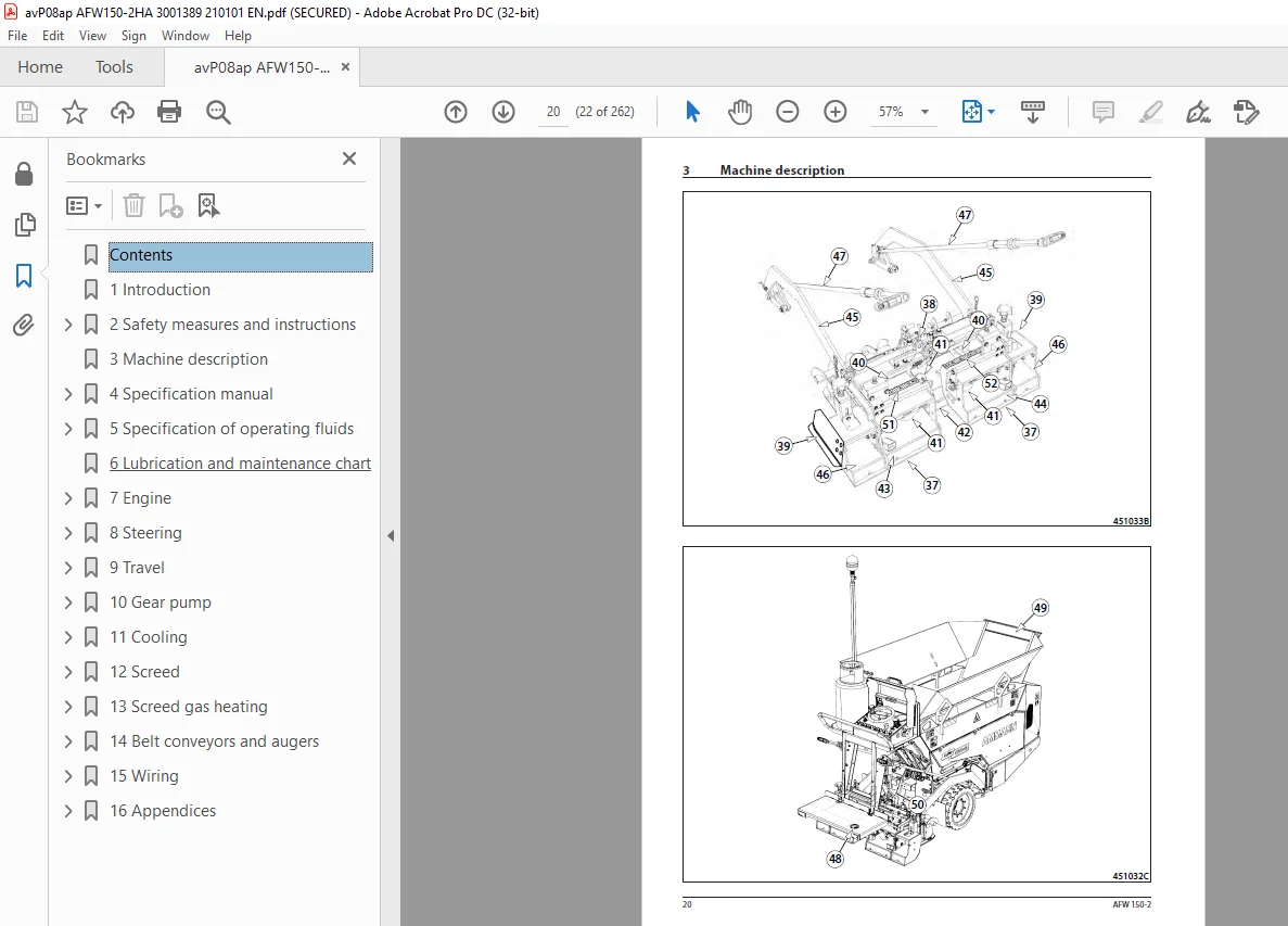
3 Machine description 19
4 Specification manual 25
4 1Basic data 26
4 2Dimensional drawing of the machine 28
4 3Technical data 30
4 4Machine gradeability and lateral static stability of the machine 32
5 Specification of operating fluids 35
5 1Engine oil 36
5 2Fuel 36
5 3Hydraulic oil 37
5 4Anti-adherent solution 37
5 5Liquid gas 38
5 6Lubricating grease 38
5 7Fluids 39
6 Lubrication and maintenance chart 41
7 Engine 45
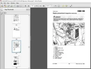
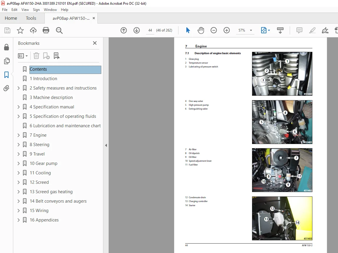
7 1Description of engine basic elements 46
7 2Technical data of the manufacturer 48
7 3Engine diagnostics 49
7 3 1Measuring glow plug resistance 49
7 3 2Measuring glow plug power supply 49
7 3 3Measuring temperature sensor 50
7 3 4Measuring lubricating oil pressure switch 51
7 3 5Measuring extinguishing valve 52
7 3 6Measuring engine speed 53
7 4Dismounting the charging controller 54
7 5Mounting the charging controller 55
7 6Dismounting the engine 56
7 7Mounting the engine 61
7 8Engine speed adjustment 66
8 Steering 69
8 1Description of basic elements 70
8 2Technical data of the manufacturer 71
8 3Diagnostics 71
8 4Replacement of the gear pump 72
8 5 Dismounting the steering linear hydraulic motor 74
8 6 Mounting the steering linear hydraulic motor 76
8 7Dismounting the steering unit 77
8 8Removal of the hydraulic tank 78
8 9Mounting the hydraulic tank 80
8 10Adjustment of the front wheel turning angle indicator 81
9 Travel 83
9 1Description of basic elements 84
9 2Diagnostics 87
9 2 1Measuring the brake switch 87
9 2 2Measuring the brake valve electromagnet Y7 88
9 2 3Measuring the refilling pressure 89
9 2 4Measuring the maximum pressure for forward and reverse travel 90
9 2 5Measuring the resistance of the electromagnet coil 92
9 3Removal of the travel pump 92
9 4Dismounting the hydraulic motor and travel gearbox 94
9 5Mounting the hydraulic motor and travel gearbox 96
10 Gear pump 99
10 1Description of basic elements 100
10 2Diagnostics 102
10 2 1Measuring the pressure of the belt conveyor and auger 102
10 2 2Measuring the screed lifting pressure 103
10 2 3Measuring the screed extension pressure 104
10 2 4Measuring the maximum vibrator pressure 105
10 2 5Measuring the vibration frequency 106
10 3 Dismounting the gear pump 107
10 4Dismounting the vibration units 108
10 5Hydraulic system switchboard 110
10 5 1Description of basic elements 110
11 Cooling 113
11 1Description of basic elements 114
11 2Cooling diagnostics 114
11 2 1Fan test 114
11 2 2Temperature sensor 114
11 3Dismounting the cooler 115
11 4Mounting the cooler 117
12 Screed 121
12 1Dismounting the screed lifting cylinder 122
12 2Replacement of linear hydraulic motors for screed extension 124
12 3Basic setting of the screed 126
12 4Replacement of the friction plates 129
12 4 1Front frame 130
12 4 2Rear frames 133
13 Screed gas heating 137
13 1Gas system diagram 138
13 2Ignition process 139
13 3Diagnostics 141
13 3 1Gas equipment tightness check 141
13 4Reducing valve 143
13 5Gas hoses 143
13 6Gas manifold 143
13 6 1Gas manifold replacement 143
13 7Screed heating burner 145
13 7 1Screed heating burner replacement 145
13 7 2Cleaning the gas burner nozzle 146
13 7 3Gas flame adjustment 148
13 7 4Test of burner ignition 149
13 8Gas supply solenoid valves 151
13 8 1Valve cleanliness inspection 151
13 8 2Measuring resistance of the coils of gas supply valve electromagnets 152
13 8 3Measuring power supply of the coils of gas supply valve electromagnets 153
13 9Ignition units 154
13 9 1Measuring resistance on the ignition unit 154
13 9 2Voltage measurement on the cable harness of ignition units 155
13 10High-voltage cables 156
13 11Spark plugs 156
13 11 1Spark plug function test 156
13 11 2Spark plug check procedure 157
13 12Temperature sensor 158
14 Belt conveyors and augers 159
14 1Replacement of the hydraulic motor for driving the augers and the belt conveyor 160
14 2Dismounting the belt conveyor chain 163
14 3Mounting the belt conveyor chain 167
14 4Setting the belt conveyor chain sag 171
14 5Dismounting the belt conveyor chain drive 173
14 6Dismounting the auger chain 176
14 7Replacement of the drive switch of augers and belt conveyor 179
14 7 1Measuring the belt conveyor drive switch S7 180
14 8Dismounting the driving gear wheel of augers 181
14 9Replacement of consumables 182
14 9 1Belt conveyor chain guide plate 182
14 9 2 Cover plates 188
15 Wiring 189
15 1Description of basic components 190
15 1 2Central earthing points X6 and x7 191
15 2Diagnostics 192
15 2 1List of error codes displayed on the display 192
15 2 2Fuse box 195
15 2 3 Diagnostics socket 196
15 2 3 1Measuring of the CAN BUS data bus 197
15 2 3 1 1Measuring voltage of the CAN BUS data bus 197
15 2 3 1 2Measuring resistance of the CAN BUS data bus 197
15 2 4Communication with the control unit A2 by means of Bodas – service 3 5 198
15 2 4 1Connecting the machine to PC 198
15 2 4 2Uploading and deleting errors 201
15 2 4 3Check of parameters 202
15 2 5Display measurement 203
15 2 6Foot switch measurement 204
15 2 7Travel controller measurement 205
15 2 8Paving speed selector measurement 207
15 3Calibration 210
15 3 1Connecting the machine to PC 210
15 3 2Calibration of the travel controller and the paving speed selector 211
15 3 3Travel pump calibration 216
15 4Control unit A2 223
15 4 1Connector of the control unit 224
15 4 2Dismounting the control unit A2 228
15 5Display unit 229
15 5 1Dismounting the display 229
15 6Travel controller 231
15 6 1Dismounting the travel controller A4 231
15 7Paving speed selector 233
15 7 1Dismounting the paving speed selector 233
15 8Battery 236
16 Appendices 237
16 1Machine wiring diagram 238
16 2Machine hydraulic system diagram 256
16 2 1Measuring points of the hydraulic circuit 258
16 3Screed gas heating system diagram 259
Customer Support: [email protected]
S.V