Trusted Business
Verified & Licensed
Virus Free Files
100% Safe Downloads
Secure Payment
SSL Protected
Instant Delivery
Available Immediately
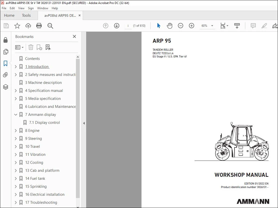
Ammann ARP 95 Tandem Roller Workshop Manual 3026131 PDF
$31.95
Ammann ARP 95 Tandem Roller Deutz TCD3.6 L4 EU Stage V / U.S. EPA Tier 4f Workshop Manual (3026131) is a comprehensive guide for technicians. It provides detailed instructions for efficient repairs, ensuring optimal performance for the specified equipment.
Instant PDF Download
Available immediately
Save to Your Device
Download & keep forever
Antivirus Scanned
100% virus-free
Trusted Worldwide
175,000+ customers
Description
Ammann ARP 95 Tandem Roller Deutz TCD3,6 L4 EU Stage V / U.S. EPA Tier 4f Workshop Manual SN 3026131 – PDF DOWNLOAD
FILE DETAILS:
Ammann ARP 95 Tandem Roller Deutz TCD3,6 L4 EU Stage V / U.S. EPA Tier 4f Workshop Manual SN 3026131 – PDF DOWNLOAD
Language : English
Pages : 610
Downloadable : Yes
File Type : PDF
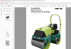
IMAGES PREVIEW OF THE MANUAL:
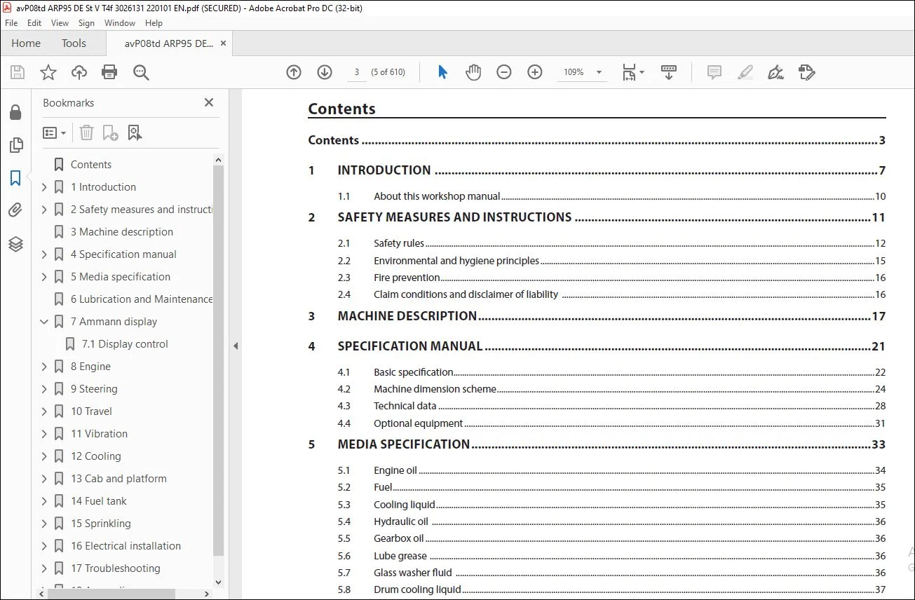
TABLE OF CONTENTS:
Ammann ARP 95 Tandem Roller Deutz TCD3,6 L4 EU Stage V / U.S. EPA Tier 4f Workshop Manual SN 3026131 – PDF DOWNLOAD
Contents 5
1 Introduction 9
1 1About this workshop manual 12
2 Safety measures and instructions 13
2 1Safety rules 14
2 2Environmental and hygiene principles 17
2 3Fire prevention 18
2 4Claim conditions and disclaimer of liability 18
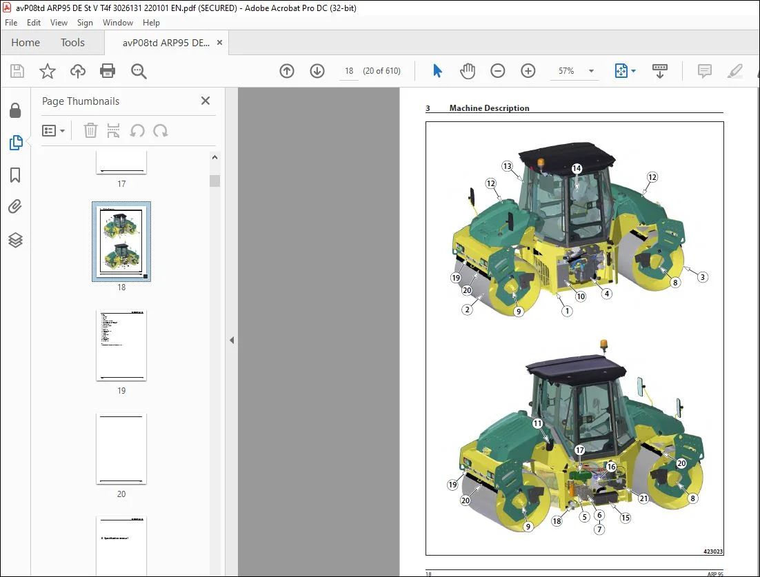
3 Machine description 19
4 Specification manual 23
4 1Basic specification 24
4 2Machine dimension scheme 26
4 3Technical data 30
4 4Optional equipment 33
5 Media specification 35
5 1Engine oil 36
5 2Fuel 37
5 3Cooling liquid 37
5 4Hydraulic oil 38
5 5Gearbox oil 38
5 6Lube grease 38
5 7Glass washer fluid 38
5 8Drum cooling liquid 39
5 9Air Conditioning filling 39
5 10Vibratory oil 39
5 11Emulsion 39
5 12DEF (AdBlue) 39
5 13Media 40
6 Lubrication and Maintenance Chart 41
7 Ammann display 47
7 1Display control 48
8 Engine 59
8 1Description of the engine and basic components 61
8 2Technical data of the manufacturer 62
8 3Troubleshooting 63
8 4Engine removal 68
8 4 1Removal of the frame with the engine from the machine 69
8 4 2Removal of the engine from the frame 74
8 4 3Engine installation 80
9 Steering 81
9 1Description of basic elements 83
9 4Removal of the linear hydraulic motor of steering 85
9 4 1Replacement of the linear hydraulic motor of steering 85
9 4 2Replacement of the linear hydraulic motor of cab lifting 87
9 4 3Replacement of seals of the linear hydraulic motor 91
9 5Removal of the steering wheel 96
9 6Removal of the steering pump 99
9 6 1Installation of the steering pump 102
9 7Removal of the hydraulic tank 105
9 7 1Installation of the hydraulic tank 109
9 8Removal of the oscillation plate bearings (003-051-1) 112
9 8 1Installation of the oscillation plate bearings (003-051-1) 117
9 9Steering block replacement 126
9 10Setting the stops and setting the planeness 132
9 10 1Adjustment of the stops 132
9 10 2Adjustment of the planeness 133
10 Travel 135
10 1Description of the basic elements 137
10 4Removal of the travel hydraulic motor 138
10 4 1Installation of the travel hydraulic motor 152
10 5Removal of the ACE travel hydraulic motor 164
10 5 1Installation of the ACE travel hydraulic motor 171
10 6Removal of the travel gearbox and hydraulic motor of ARP95 K 178
10 6 1Installation of the travel gearbox and hydraulic motor of ARP95 K 183
10 7Removal of the travel pump 185
10 7 1Installation of the travel pump 191
10 8Removal of the travel pump coupling 194
10 8 1Installation of the travel pump coupling 197
11 Vibration 199
11 1Description of the basic elements 201
11 4Removal of the vibration hydraulic motor 203
11 4 1Installation of the vibration hydraulic motor 207
11 5Removal of the vibration pump – rear drum 210
11 5 1Installation of the vibration pump – rear drum 214
11 6Removal of the vibration pump – front drum 216
11 6 1Installation of the vibration pump – front drum 220
11 7Removal of the drum from the machine 223
11 7 1Installation of the drum in the machine 234
11 7 2Installation of the damper plate – classic drum 243
11 8Removal of vibrator bearings 247
11 8 1Covers – removal of bearings 247
11 8 2Vibrator – removal of inner rings 259
11 9Installation of vibrator bearings 263
11 9 1Covers – installation of bearings 263
11 9 2Vibrator – installation of inner rings 266
11 10Replacement of drum rubber-metals 269
11 11Removal of the ACE vibrator 273
11 11 1Remove of the ACE gearbox hydraulic motor 273
11 11 2Removal of the vibrator from an ACE drum 279
11 11 3Removal of inner bearing rings 284
11 11 4Removal of bearings 291
11 11 5Removal of the outer eccentric 295
11 11 6Removal of the inner eccentric 298
11 12Installation of the ACE vibrator 300
11 12 1Installation of the inner eccentric 300
11 12 2Installation of the outer eccentric 305
11 12 3Installation of bearings 310
11 12 4Installation of inner bearing rings 315
11 12 5Installation of the vibrator in the drum 320
11 12 6Mechanical setting of ACE system shaft and eccentric masses 328
11 12 7Installation of the ACE gearbox hydraulic cylinder 330
11 12 7 1 Linear sensor setting 336
11 12 8Installation of the damper plate – ACE drum 338
11 13Replacement of ACE drum rubber-metals 342
11 14Adjustment of the vibration frequency 346
11 15ACE PRO autocalibration 350
11 16Removal of the bearing of the standard drum and ACE drum 354
11 16 1Installation of the bearing of the standard drum and ACE drum 360
12 Cooling 367
12 1Description of basic components of the cooling hydraulics 369
12 4Removal of the cooling hydraulic motor and propeller 370
12 4 1Installation of the cooling hydraulic motor and propeller 375
12 5Removal of the cooling pump 378
12 5 1Installation of the cooling pump 381
12 6Removal of the combined cooler 383
13 Cab and platform 389
13 1Replacement of the heater ball valve 391
13 2Replacement of the heater 395
13 3Replacement of the heater fan 398
13 4Removal of the cab 403
13 4 1Installation of the cab 415
13 5Removal of the platform 427
13 5 1Installation of the platform 435
13 6Removal of the platform rubber-metals 440
14 Fuel tank 447
14 1Removal of the fuel tank 449
14 1 1Installation of the fuel tank 451
15 Sprinkling 453
15 2Removal of the sprinkling pumps 455
15 3Removal of the front water tank 458
15 3 1Installation of the sprinkling pump 463
15 3 2Installation of the front water tank 464
15 4Removal of the rear water tank 467
15 4 1Installation of the rear water tank 471
16 Electrical installation 473
16 2Measurement technique 475
16 3Safety and instructions 476
16 4Fitting of fuses 477
16 5Removal of the seat switch 478
16 6Removal of the travel lever and switches 482
16 7Adjustment of the induction sensor 486
16 8Batteries 489
16 9Alternator 491
16 9 1Removal of the alternator 494
17 Troubleshooting 497
17 1Machine error codes 498
17 2Engine error codes 501
18 Appendices 537
18 1Measuring points 539
18 1 1Conditions to measure the refilling pressure 542
18 1 2Conditions to measure the cutter pressure 543
18 1 3Conditions to measure the pressure in the steering circuit 544
18 1 4Conditions to measure the travel pressure 545
18 1 5Conditions to measure the vibration pressure 546
18 1 6Conditions to measure the pressure in the cooling circuit 549
18 2Wiring diagram ARP 95 550
18 3Wiring diagram ARP 95 ACE 556
18 4Electric installations cable harnesses 559
18 5Hydraulic system diagram ARP 95 598
18 6Hydraulic system diagram ARP 95 C 600
18 7Hydraulic system diagram ARP 95 ACE 602
18 8Hydraulic system diagram ARP 95C ACE 604
18 9Check the tightening of bolted connections 606
Contact us: [email protected]
https://vimeo.com/897701258?share=copy
S.V