
APS3200 APU Illustrated Parts Catalog – Hamilton Sundstrand A320 IPC Rev 33 PDF
Original price was: $44.95.$29.95Current price is: $29.95.
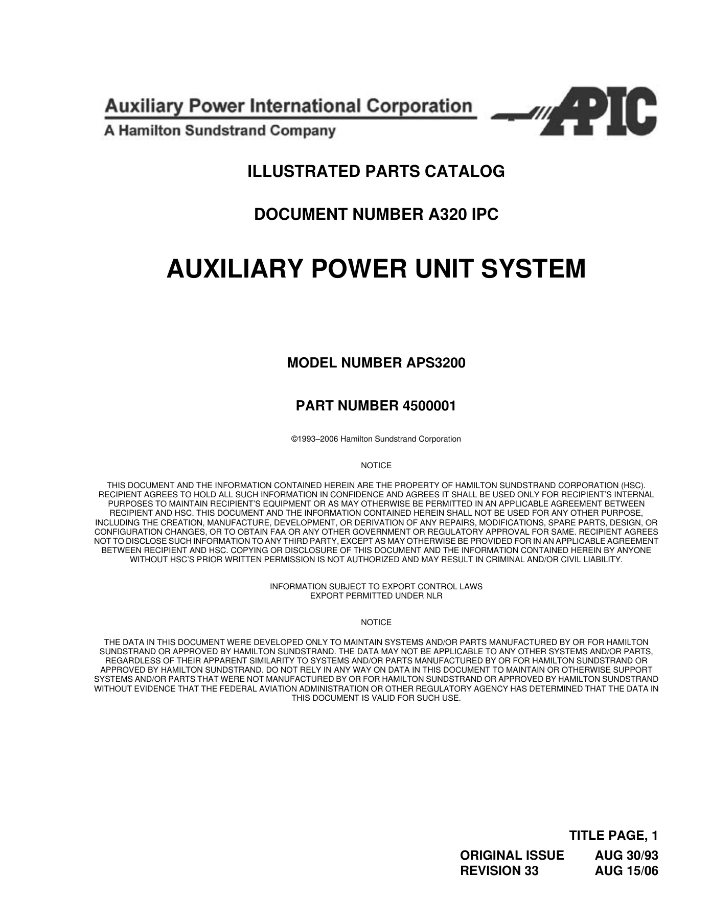
Complete Hamilton Sundstrand APIC APS3200 Auxiliary Power Unit Illustrated Parts Catalog, Document A320 IPC Revision 33. Exploded figures, item callouts, part numbers, effectivity codes and full alphanumerical and numerical indexes for APU Part Number 4500001 series on Airbus A318/A319/A320/A321.
Description
Hamilton Sundstrand APIC APS3200 Auxiliary Power Unit Illustrated Parts Catalog – Document Number A320 IPC, Revision 33, dated August 15, 2006, covering the APS3200 APU, Part Number 4500001 series, as installed on the Airbus A318, A319, A320 and A321. Revision 33 is a complete reissue: every figure reference, item callout, part number and effectivity note was rebuilt to current Hamilton Sundstrand engineering, so the illustrations and listings in this APS3200 parts catalog describe the hardware as it is actually configured rather than an older build standard. When you need to identify a component, confirm what belongs on a specific serial number, or check whether a part is superseded, optional or alternate before you order it, this is the document that answers the question.
File Details
- Manual type: Illustrated Parts Catalog (IPC)
- Equipment: Auxiliary Power Unit, Model APS3200, Part Number 4500001 series
- Application: Airbus A318 / A319 / A320 / A321
- Manufacturer: Hamilton Sundstrand Corporation / Auxiliary Power International Corporation (APIC)
- Document number: A320 IPC
- Revision: Revision 33, dated August 15, 2006
- Language: English
- Page count: 514 pages
- File format: PDF
Chapters Covered
- Introduction
- Service Bulletins
- Alphanumerical Index
- Numerical Index
- Detailed Parts List – 49-00-00 APU System
- Detailed Parts List – 49-10-00 APU Assembly
- Detailed Parts List – 49-20-00 Engine Assembly
- Detailed Parts List – 49-20-91 Gearbox / Compressor
- Detailed Parts List – 49-20-92 Compressor / Power
- Detailed Parts List – 49-21-00 Power Section
- Detailed Parts List – 49-21-10 Combustor Assembly
- Detailed Parts List – 49-23-00 Load Compressor
- Detailed Parts List – 49-23-10 Inlet G. Vane Assembly
- Detailed Parts List – 49-26-00 Gearbox Assembly
- Detailed Parts List – 49-71-10 Module Ident Assembly
APU System and APU Assembly (49-00-00 / 49-10-00)
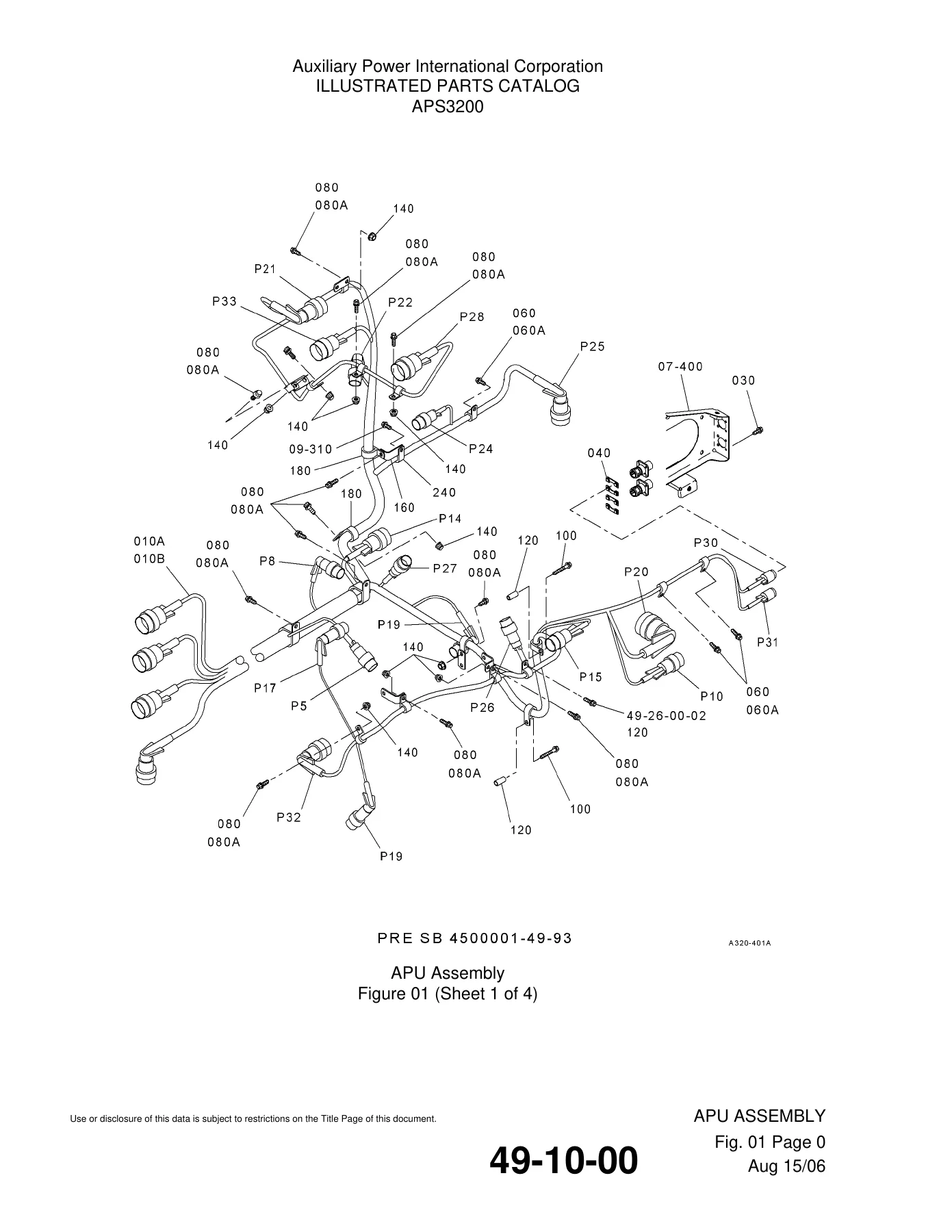
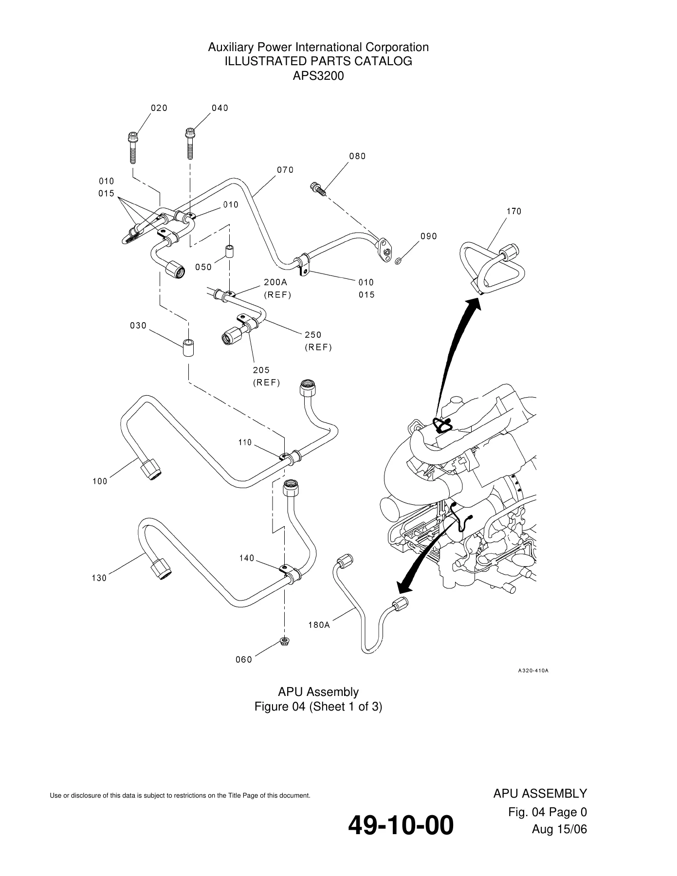
The opening section carries the pictorial index that walks the complete APU down into its modular groups, followed by the largest figure set in the book. Figures 01 through 12 of 49-10-00 break out the external plumbing and electrical installation: harness routing drawn on separate pre- and post-SB4500001-49-93 sheets, loop clamps, spacers, sleeve bolts and self-locking nuts, thermocouples tagged T/C-1 and T/C-2 against equipment designators P-30 and P-31, the turbine ignition exciter with its cables and identification labels, lubrication and vent tube assemblies, fuel drain and pneumatic lines, PCD and IGV actuator tubing, the oil cooler with cooling fan outlet duct and compartment cooling valve, the cooling fan and starter motor with their attaching hardware and V-band clamps, fuel control mounting and flow divider, the air bypass duct and bleed control valve with insulation blanket segments and tailpipe, the inlet guide vane actuator, inlet pressure and temperature sensor, low oil pressure switch and compressor discharge sensor, the plenum and its support brackets, the plenum half assemblies with screens and inserts, and a closing protective cover list. Each item line gives figure, item, part number, airline part number, nomenclature, effectivity code and units per assembly.
Engine Assembly and Module Attaching Hardware (49-20-00 / 49-20-91 / 49-20-92)
The bare APU build-ups are listed here, including the gearbox outline series, the load compressor module variants, the power section module range and the attaching hardware packages that tie the modules together. The two hardware chapters itemize the smaller pieces that are easy to get wrong on reassembly – self-locking nuts, O-rings, the oil transfer tube, retaining ring, quill shaft, front thrust nut, sealing ring and the compressor-to-power-section bolt set – with pre- and post-service-bulletin notes marking where the configuration changed.
Power Section (49-21-00)
Fourteen figure groups cover the hot end of the APS3200 in detail: the compressor housing and its threaded inserts and dowels, the generator diffuser, first and second stage turbine wheels and disks, the first stage turbine nozzle assemblies, the rear bearing box and rear bearing housing assembly, the exhaust casing variants, and the generator shielding. Figure 01A separately breaks down the M4503908 mod part series so the correct turbine wheel and nozzle combination can be traced to the build standard. Shim washer families are listed with their thickness ranges and SELECT FROM notes instead of being hidden behind a single part number.
Combustor Assembly (49-21-10)
Eight figures take the combustor from kit level down to individual liners. The listings cover the main and pilot fuel manifolds, main fuel nozzle assembly and pilot fuel nozzle assembly, igniter, drain valve, chamber assembly with its cooling strips, inner and outer liners, bosses and doublers, and the containment shield assembly. Repair-part and interchangeability notes are carried in the nomenclature column so alternate nozzle and liner part numbers are visible at the point of use.
Load Compressor (49-23-00) and Inlet Guide Vane Assembly (49-23-10)
The load compressor figures run from the hoisting eye and support bracket through the front bearing nut, carrier, ball and roller bearings, carbon seal kits, rotor assembly, diffuser, containment shield and adjusting washer sets, out to the scroll – including the later scroll part number released under SB4500001-49-99. The inlet guide vane chapters itemize the vanes, sector gears, bearing support assembly, bushings, inlet hub, inlet shroud and inlet housing, with the smaller hardware broken out into separate inserts and rings rather than grouped.
Gearbox Assembly (49-26-00)
Eleven figures cover the accessory gearbox in full: filter latch and filter element, differential pressure indicator and switch indicator, relief valve, magnetic drain plug, oil level sensor, solenoid valve, oil filler tube assembly, temperature sensor, sight glass, quick disconnect couplings, start motor bearing support with its overrunning starter clutch, idler gearshaft assembly, high-speed pinion matched set, generator gearshaft, lube pump rotor assembly, and finally the matched gearbox housing set with its inserts, bearing liners and retaining hardware.
Module Ident Assembly (49-71-10)
The engine serial number identification assembly is broken down into its connector, end seal plugs, electrical contacts, silicone pad, connector cap and printed wiring assembly – the parts you need when the identification plate or its wiring is damaged and the serial number record has to be restored.
Service Bulletins and Indexes
The front matter carries a service bulletin list running from SB4500001-49-1 through SB4500001-49-100, each with its description and the engine serial number effectivity it applies to, so a modification state can be confirmed against the unit in hand before any part is ordered. Two master indexes follow: an alphanumerical index and a numerical index, both mapping part number to chapter, section, unit, figure, item and total required quantity, including the AN, MS and NAS standard hardware that fills out most of the smaller callouts.
What This APS3200 Parts Catalog Lets You Do
An APU is not a single assembly – it is a stack of modules with plumbing, harnesses and hardware layered over them, and the difference between a two-hour task and a two-day one is usually whether the right part number was ordered the first time. This catalog supports the full range of parts work on the APS3200: identifying a component from an exploded view, tracing an assembly down through its indenture levels, confirming whether a part is superseded, replaced, alternate or optional, checking effectivity against a serial number, and building an accurate order for a repair, a hot section inspection or a module swap. The effectivity codes, pre- and post-service-bulletin notes and dimensional data on shims and washers are exactly the details that prevent a wrong-part return and a grounded aircraft.
Because the APS3200 is a line-replaceable APU with a fixed part number series, the parts data has to be read against the specific build. The blue cross-references to the Component Maintenance Manual figures, the equipment designators printed against thermocouples and clamps, and the assembly part number notes added for clarity in this revision all make that traceability faster than working from a generic hardware list. Standard hardware is called out with its full specification – thread size, length in inches and millimetres, CAGE code where it is not 0LYZ0 – so a bolt is never ordered on guesswork.
IMAGES PREVIEW
Instant PDF Delivery
This is the complete 514-page Revision 33 catalog delivered as a PDF the moment payment clears. No shipping, no waiting on a courier, no missing binder. Open it on a laptop at the gate, on a tablet on the hangar floor, or send the relevant figure to the print room and hand a paper copy to the technician doing the work. Every illustration and listing in the APS3200 APU Illustrated Parts Catalog is there in one file, ready to search by part number or work through figure by figure.
Reviews
There are no reviews yet.