
ArduPilot Plane V4.3.8 Complete Parameter List – Full MAVLink Parameter Reference PDF
Original price was: $39.95.$24.95Current price is: $24.95.
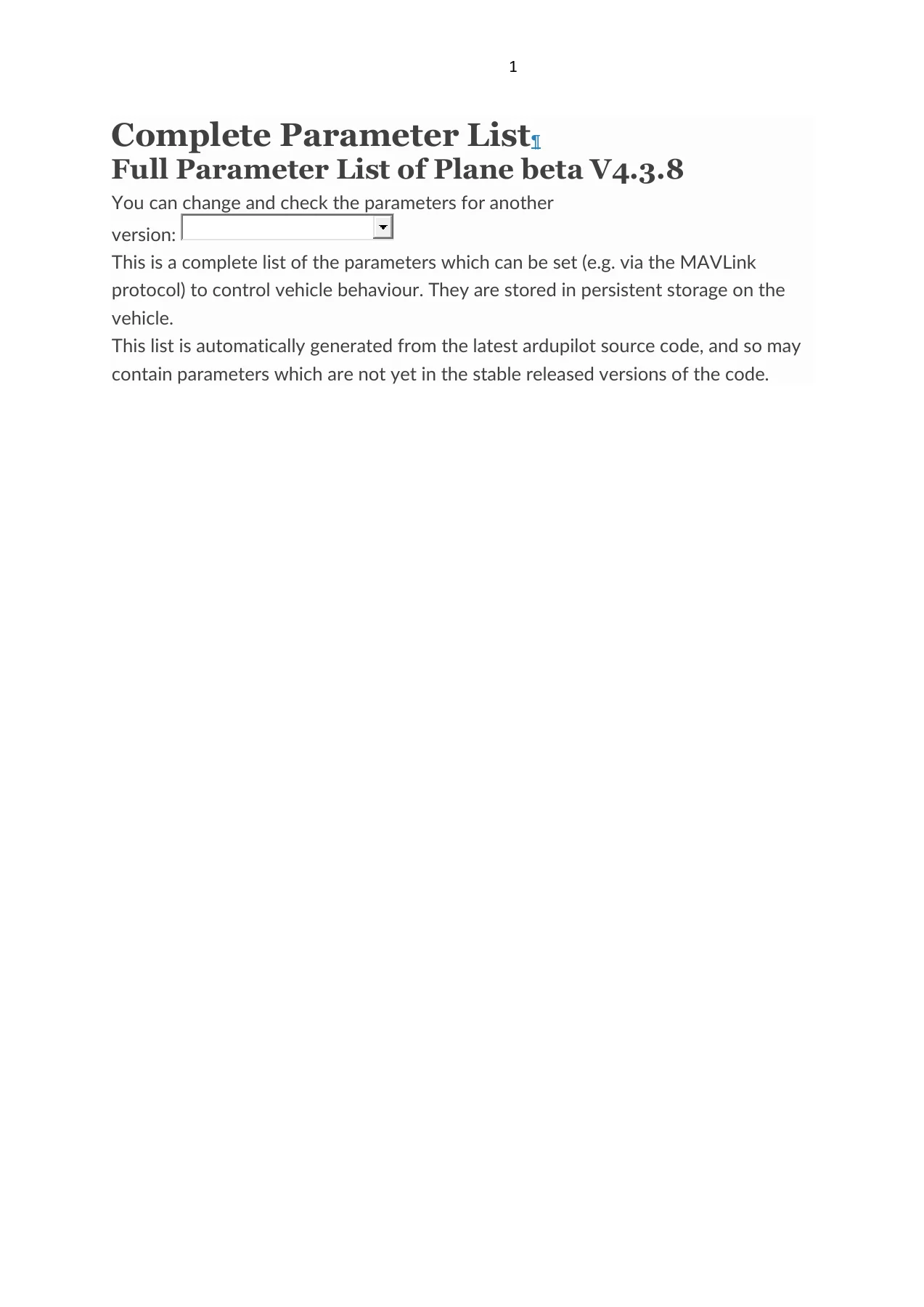
The complete parameter list for ArduPilot Plane beta V4.3.8 – every configurable parameter, range, unit, increment and bitmask for fixed wing and QuadPlane autopilots, in one 964-page PDF reference.
Description
The ArduPilot Plane Complete Parameter List is the full parameter reference for ArduPilot Plane beta V4.3.8, the document you reach for when an autopilot has to be configured, tuned or troubleshot at parameter level rather than by guesswork. Every setting that can be written over MAVLink or from a ground station is documented here with its name, description, accepted range, increment, units, and – where one exists – the complete bitmask or enumerated value table behind it.
This is not an introductory flight guide. It is the reference the firmware generates about itself, and it states exactly what each parameter does, which values it will accept, and how the flight controller responds when the value changes. ArduPilot Plane beta V4.3.8 reworked a great deal across navigation, EKF3 source selection, QuadPlane and tailsitter control, harmonic notch filtering, scripting and OSD layout. If you are flying the beta firmware, this is the parameter list that matches the code in the aircraft.
File Details
- Document type: Complete parameter list / full parameter reference
- Firmware covered: ArduPilot Plane beta V4.3.8
- Brand: ArduPilot
- Vehicle type: Plane (fixed wing), including QuadPlane VTOL parameter sets
- Language: English
- Page count: 964 pages
- File format: PDF
- Structure: Parameters grouped by prefix, each with description, range, increment, units, values and bitmask tables
What the ArduPilot Plane V4.3.8 Parameter List Gives You
A parameter list is only useful if it is complete, and this one is. It opens with the ArduPlane core parameters – firmware versioning, MAVLink system IDs, ground station identity, autotune aggressiveness, telemetry delay, GCS PID tuning mask, rudder and throttle mixing, glide slope handling, stick mixing, takeoff throttle and rotation behaviour, altitude offsets, waypoint radii and loiter radii, stall prevention, airspeed limits, throttle limits and slew rates, failsafe actions and timeouts, flight mode channel and switch assignments, bank and pitch limits, ACRO rates, mixing gain and offset, logging bitmask, trim values, flap scheduling, crash detection and RTL autoland behaviour.
From there it works through every subsystem prefix in the firmware. Barometers and their wind coefficients, compass calibration matrices and per-motor compensation, airspeed sensors including the full second-sensor set, EKF2 and EKF3 noise, gate, delay, drag and source parameters, GPS receiver types, blending, moving baseline and antenna offsets, rangefinders from instance 1 through 9 plus instance A, RPM sensors, RSSI sources, battery monitors BATT through BATT9, arming checks, ADS-B and AIS, avoidance behaviour, Advanced Failsafe termination, camera and RunCam control, gimbal mounts 1 and 2, landing gear, parachute release, gripper, generator, internal combustion engine control, ICE idle governor, harmonic notch filtering and FFT analysis, batch IMU logging, IMU temperature calibration, scripting, scheduler, serial ports 0 to 9, servo outputs 1 to 32, and the complete on-screen display layout parameters for OSD1 through OSD6.
The QuadPlane half of the list is equally deep: frame class and type, motor and thrust curve settings, battery voltage compensation, current limiting, PWM output types, position and velocity controllers on all three axes, loiter behaviour, weathervaning, waypoint speed and acceleration, tiltrotor and tailsitter configuration, and QACRO rates. For anyone running a VTOL conversion on Plane firmware, these are the parameters that decide whether the transition works.
Parameter Groups Documented
- ADSB – hardware type, vehicle list size, radius and altitude filters, ICAO ID, emitter type, squawk code, RF selection and capabilities, logging, special vehicle tracking
- AFS – advanced failsafe enable, manual, heartbeat and terminate pins, comms and GPS loss waypoints, AMSL limits and error margin, QNH pressure, geofence and RC failsafe, dual loss termination, maximum range
- AHRS – GPS gain and use, yaw P, RP P, maximum wind, trim roll, pitch and yaw, board orientation, velocity complementary filter beta, minimum satellites, EKF type, custom orientation offsets
- AIS – receiver type, vessel list size, timeout, logging options
- Arming – arming requirements, accelerometer error threshold, rudder arming, required mission items, arm check bitmask, arming options
- ARSPD and ARSPD2 – sensor type, device ID, use, offset, ratio, pin, autocal, tube order, skip calibration, PSI range, I2C bus, primary sensor, options, wind mismatch limits and re-enable gate
- AVD – avoidance enable, fail and warn actions, recovery behaviour, obstacle count, time horizons, XY and Z distances, minimum avoidance altitude
- BARO – ground pressure, ground temperature, altitude offset, primary barometer, external bus, probe mask, device IDs, field elevation, altitude error maximum, options
- BARO WCF – wind coefficient enable plus forward, backward, right and left static pressure error coefficients for barometers 1 to 3
- BATT and BATT2 to BATT9 – monitor type, capacity, watt limit, serial number, low voltage timeout, failsafe voltage source, low and critical voltage and capacity thresholds, failsafe actions, arming voltage and capacity, monitor options, voltage and current pins, multipliers, offsets, I2C bus and address, sum mask, current multiplier, fuel level voltage, multiplier, filter and pin
- BRD – serial flow control on ports 1 to 5, safety switch enable, SBUS output rate, user serial number, safety output mask, heater target and gains, board type, IO co-processor enable, safety button options, VBUS and VSERVO minimums, SD slowdown, PWM output voltage, board options, boot delay, alternative hardware configuration, heater low margin
- BRD_RADIO – directly attached radio type, air protocol, debug level, CRC control, RSSI and packet-rate channels, DSM telemetry, transmit power, FCC test mode, stick mode, factory test channel, telemetry RSSI and PPS channels, maximum transmit power, buzzer adjustment, auto-bind time and level
- BRD_RTC – allowed RTC time sources and timezone offset
- BTN – button reporting enable, four button input pins, report send time, per-pin PWM/invert options and per-pin RC function assignment
- CAM and CAM_RC – shutter type, shutter duration, servo on and off PWM, trigger distance, relay polarity, minimum interval, maximum roll, feedback pin and polarity, auto-only triggering, camera type; RunCam device type, available features, boot, button and mode delays, OSD menu control options
- CAN, CAN_D1 to CAN_D3, CAN_P1 to CAN_P3, CAN_SLCAN – log level, per-driver protocol selection, KDE pole count, Piccolo ESC and servo channel masks and rates, ECU node ID and rate, CAN tester index and loop rate, UAVCAN node, servo and ESC bitmasks, output rates, options, notify rate, ESC offset, memory pool, physical driver index, bitrate, CANFD bitrate, SLCAN route, serial port, timeout and start delay
- CHUTE – parachute enable, release mechanism type, servo on and off PWM, minimum altitude, release delay, critical sink rate, options
- COMPASS – offsets X, Y, Z for three compasses, declination, learn mode, use flags, auto declination, motor interference compensation type and per-axis values, orientation, external flags, device IDs, soft-iron diagonal and off-diagonal terms, calibration fitness, maximum offset, driver type mask, filter range, auto rotation, priority IDs, enable, scale factors, options, custom orientation angles
- COMPASS_PMOT – per-motor compass correction enable, exponential correction, and per-motor X, Y and Z compensation for motors 1 to 4
- CUST_ROT – custom rotation enable, custom 1 and custom 2 roll, pitch and yaw
- DID – OpenDroneID enable, MAVLink port, DroneCAN driver, options, barometer vertical accuracy
- EAHRS – external AHRS type and data rate
- EFI – EFI communication type, fuel flow calibration coefficients, ECU fuel density
- EK2 and EK3 – enable, GPS mode control, horizontal, vertical and position measurement noise, velocity and position innovation gates, glitch radius, altitude source and noise, height gate and delay, magnetometer noise, fusion mode and gate, airspeed noise and gate, rangefinder noise and gate, optical flow maximum rate, noise, gate and delay, gyro and accelerometer process noise, gyro and accelerometer bias stability, wind process noise and height scale, GPS preflight check bitmask, IMU mask, accuracy check scaler, non-GPS position uncertainty, yaw noise and gate, output filter time constant, earth and body magnetic field process noise, rangefinder switch height, terrain gradient, beacon noise, gate and delay, rangefinder maximum ground speed, accelerometer bias limit, magnetometer force mask, origin height correction mask, visual odometry error bounds, wheel encoder velocity error, sideslip fusion mask, EKF-GSF run, use and reset masks, lane error threshold, sensor affinity, drag ballistic coefficients, drag observation noise and momentum coefficient, on-ground not moving test scale factor, ground effect dead zone, primary core, log level, GPS vertical accuracy threshold
- EK3_SRC – primary, secondary and tertiary horizontal position, horizontal velocity, vertical position, vertical velocity and yaw sources, plus source options bitmask
- ESC_TLM – ESC telemetry MAVLink numbering offset
- FENCE – fence enable, type bitmask, action, maximum and minimum altitude, circle radius, margin, polygon point total, return to rally, return altitude, auto-enable, options
- FFT – analyser enable, minimum and maximum frequency, sample mode, window size and overlap, learned hover frequency, thrust reference, SNR reference, attenuation, learned bandwidth, harmonic fit threshold and harmonic peak target, output frames to average
- FLOW – optical flow sensor type, X and Y scale factor correction, yaw alignment, X, Y and Z position offsets, bus address
- FOLL – follow enable, target system ID, maximum follow distance, offset type and north, east and down offsets, yaw behaviour, position error P gain, altitude type
- FRSKY – uplink sensor ID, first, second and default downlink sensor IDs, telemetry options
- GEN – generator type and options
- GPS, GPS_MB1 and GPS_MB2 – first and second GPS type, navigation filter setting, auto switchover behaviour, minimum DGPS lock type, SBAS mode, minimum elevation, injection destination, SBP log mask, raw data logging, GNSS constellation mask for both receivers, save configuration, auto configuration, update rates, antenna position offsets, measurement delays, blending mask and time constant, driver options, physical COM ports, primary GPS, DroneCAN node IDs and overrides; moving base type and base antenna X, Y, Z offsets
- GRIP – gripper enable, gripper type, grab, release and neutral PWM, EPM regrab interval, DroneCAN hardpoint ID, autoclose time
- GUIDED – proportional, integral, derivative and feed-forward gains, integrator maximum, target, error and derivative filter frequencies, slew rate limit
- ICE – internal combustion engine enable, start channel, starter run time, start delay, RPM threshold, ignition and starter PWM on and off values, RPM channel, start and idle throttle percentages, idle RPM setpoint, deadband and slew rate, options, start channel minimum PWM, redline RPM
- INS – gyro offsets for three IMUs, accelerometer scaling and offsets for three IMUs, gyro and accelerometer filter cutoff frequencies, IMU use flags, stillness threshold, gyro calibration scheme, accelerometer trim option and body-fixed accelerometer, IMU X, Y, Z position offsets, gyro and accelerometer device IDs, fast sample mask, IMU enable mask, gyro rate, calibration temperatures, temperature calibration persistence
- INS_HNTC2 and INS_HNTCH – harmonic notch filter enable, base frequency, bandwidth, attenuation, harmonic bitmask, reference value, dynamic frequency tracking mode, options including double and triple notch, update at loop rate and enable on all IMUs, throttle notch minimum frequency ratio
- INS_LOG – batch sample count, sensor bitmask, batch logging options, logging interval and logging count
- INS_TCAL1 to INS_TCAL3 – temperature calibration enable, minimum and maximum valid temperature, accelerometer and gyroscope first, second and third order temperature coefficients on all three axes
- LAND and LAND_DS – landing slope re-calc threshold, auto-abort slope threshold, landing pitch, flare altitude and time, pre-flare altitude, time and airspeed, landing throttle slew rate, disarm delay, servo neutral after landing, throttle-based abort, landing flap percentage, landing options, auto-landing type; deepstall forward and down velocity, slope A and B, approach extension, slew speed, elevator PWM, maximum and minimum airspeed, L1 period, I gain, yaw rate limit, time constant, P, I and D gains, integrator maximum, minimum abort altitude, aileron scaling
- LGR – landing gear enable, startup behaviour, deploy and weight-on-wheels feedback pins and polarity, deploy and retract altitudes, auto retract and deploy options
- LOG – backend type, file and block buffer size, logging while disarmed, replay logging, file rotation on disarm, MAVLink buffer size, file timeout, minimum free space, file, MAVLink and block rate limits
- MIS – total mission commands, mission restart behaviour, mission options bitmask
- MNT1 and MNT2 – mount type, default operating mode, RC rate, roll, pitch and yaw minimum and maximum angles, retracted and neutral angles, roll and pitch stabilization lead time
- MSP – cell count override, MSP OSD options
- NAVL1 – L1 control period, damping ratio, crosstrack integrator gain, loiter radius bank angle limit
- NTF – LED brightness, buzzer driver types, LED colour override source, on-board display type, OreoLED theme, buzzer pin, LED driver types, buzzer-on pin logic level, buzzer volume, serial LED string length
- OSD and OSD1 to OSD6 – OSD type, screen switch channel and method, options, font, vertical and horizontal offset, RSSI, satellite, battery voltage, terrain, average cell voltage and resting voltage warning levels, display units, message duration, arm, disarm and failsafe screens, button delay, cell count, plus per-screen enable, PWM limits and element position for altitude, battery voltage, current, capacity used, satellites, flight mode, messages, ground speed, horizon, home, heading, throttle, compass, wind, airspeed, climb rate, ESC temperature, RPM and current, GPS latitude and longitude, roll, pitch, temperature, HDOP, waypoint, crosstrack, distance, stats, flight time, climb efficiency, efficiency, barometer and airspeed temperatures, second battery voltage and capacity, both airspeed sensors, clock, sidebars, crosshair, home distance and direction, power, cell voltage, battery bar, arming, pluscode, callsign, second battery current, VTX power, terrain height, average cell voltage, resting voltage, fence, rangefinder and link quality, plus text resolution and font index. OSD5 and OSD6 add save buttons and nine scriptable parameter display slots each
- PTCH and RLL – pitch and roll time constants, maximum up, down and roll rates, roll compensation, rate controller P, I, IMAX, D and FF gains, target, error and derivative filter frequencies, slew rate limits
- Q_ and QuadPlane groups – QuadPlane enable, maximum lean angle, transition time, pilot vertical speeds, vertical acceleration, RC output rate, assistance speed, angle, altitude and delay, maximum yaw rate, land speed and final altitude, transition pitch, frame class and type, forward velocity hold gain and altitude cutoff, QRTL altitude and RTL mode, guided mode VTOL, ESC calibration, ICE cut on landing, MAVLink type, QuadPlane option bitmask, transition deceleration, trim pitch, fixed wing landing approach radius, transition failure time and action, throttle expo, QACRO roll, pitch and yaw rates, takeoff failure scalar and airspeed limit, manual forward throttle maximum, back transition duration, land detection altitude change threshold, minimum navigation altitude, pilot yaw rate, expo and time constant
- Q_AUTOTUNE – autotune axis bitmask, aggressiveness, minimum D gain
- Q_A – yaw target slew rate, yaw, roll and pitch acceleration maximums, rate feed-forward enable, angle boost, roll, pitch and yaw angle P gains, angle limit time constant, angular velocity maximums on all three axes, attitude control input time constant, roll, pitch and yaw rate controller P, I, IMAX, D and FF gains, filter frequencies and slew rate limits, throttle mix minimum, maximum and manual
- Q_LOIT – loiter pilot angle maximum, horizontal maximum speed, maximum correction acceleration, braking acceleration and jerk, brake start delay
- Q_M – matrix yaw minimum, thrust curve expo, motor spin maximum, minimum and armed, battery voltage compensation maximum and minimum, motor current maximum and time constant, output PWM type, PWM minimum and maximum, thrust hover value and hover learning, PWM disable when disarmed, yaw servo maximum lean angle, spool up time, boost scale, battery compensation index, output slew up and down times, safe time
- Q_P – XY acceleration filter cutoff, position and velocity vertical P, I, IMAX, D and FF gains, vertical error and D-term filters, acceleration vertical P, I, IMAX, D and FF gains with filters and slew limit, position horizontal P gain, velocity horizontal P, I, D, IMAX and FF gains with filters, position control angle maximum, horizontal and vertical jerk limits for input shaping
- Q_TAILSIT – tailsitter enable, fixed wing and VTOL transition angles, input type bitmask, vector thrust gain in forward flight and hover, vector thrust gain power, maximum gain scaling, maximum roll angle, motor mask, gain scaling mask, minimum gain scaling, disk loading, VTOL to forward and forward to VTOL transition rates, forward to VTOL transition throttle, VTOL control surface roll, pitch and yaw gains, minimum outflow speed
- Q_TILT – tiltrotor enable, tiltrotor mask, upwards and downwards tilt rates, maximum VTOL angle, tiltrotor type, yaw angle, fixed wing tilt angle and gain, wing flap tilt angle
- Q_WP – waypoint horizontal speed target, waypoint radius, climb and descent speed targets, horizontal and vertical acceleration, rangefinder terrain following, jerk, terrain following altitude margin
- Q_WVANE – weathervaning enable, gain, minimum angle and height, maximum ground speed and vertical speed, takeoff and landing overrides, weathervaning options
- RALLY – rally total, rally limit, include home
- RC, RC1 to RC16, RCMAP – RC override timeout, RC options bitmask, enabled RC protocols bitmask; minimum, trim and maximum PWM, reversed flag, dead zone and channel option for each of the sixteen input channels; roll, pitch, throttle and yaw channel mapping
- RELAY – first through sixth relay pins, default relay state
- RNGFND1 to RNGFND9 and RNGFNDA – rangefinder type, pin, scaling, offset, distance function, minimum and maximum distance, stop pin, ratiometric flag, powersave range, ground clearance, bus address, X, Y and Z position offsets, orientation, moving average, moving median filter, frequency, multi-pulse averages, sensitivity threshold, baud rate, CAN receive ID and minimum signal strength for each of the ten rangefinder instances
- RPM1 and RPM2 – RPM sensor type, scaling, maximum and minimum RPM, minimum data quality, input pin, ESC telemetry channel averaging mask
- RSSI – RSSI type, analog pin, pin low and high voltage, receiver channel, channel low and high PWM
- SCHED – scheduler debug level, main loop rate, scheduler options
- SCR – scripting enable, virtual machine instruction count, heap size, debug options, six general purpose user parameters, directory disable mask
- SERIAL and SERIAL0 to SERIAL9 – baud rate, protocol selection and UART options for each serial port, plus serial pass-through first port, second port and timeout
- SERVO and SERVO1 to SERVO32 – automatic servo trim, default output rate, DShot output rate and ESC type, servo GPIO mask, 32-output enable, and minimum, maximum, trim, reversed flag and output function for every one of the thirty-two servo output channels
- SERVO_BLH – BLHeli channel bitmask, auto-enable for multicopter motors, internal interface test, protocol timeout, telemetry rate, debug level, output type override, control port, motor poles, 3D channel mask, bi-directional DShot mask, reversed channel mask
- SERVO_FTW, SERVO_ROB, SERVO_SBUS, SERVO_VOLZ – FETtec ESC output channel mask, reverse rotation mask and electrical pole count; Robotis servo position minimum and maximum; SBUS default output rate; Volz servo protocol channel bitmask
- SOAR – soaring enable, vertical speed trigger, process and measurement noise, distance to thermal centre, minimum thermalling and cruising times, polar zero-lift drag, induced drag and CL factor, maximum, minimum and cut-off altitude, maximum drift and radius, thermalling bank angle, thermalling and cruising airspeed, thermalling flap
- SR0 to SR6 – raw sensor, extended status, RC channel, raw control, position, extra data types 1 to 3, parameter and ADSB stream rates for each ground station stream group
- STAT – boot count, total flight time, total run time, statistics reset time
- STEER2SRV – steering time constant, turning gain, integrator gain and limit, damping gain, minimum speed, feed forward, derating speed, derating factor and minimum wheel angle
- TECS – maximum climb rate, minimum and maximum sink rate, controller time constant, throttle and pitch damping, integrator gain, vertical acceleration limit, height and speed complementary filter frequencies, bank angle compensation gain, speed weighting, landing airspeed and throttle, landing speed weighting, pitch maximum and minimum in auto flight, landing sink rate, land controller time constant and damping, maximum pitch in the final landing stage, approach sink rate maximum, land sink rate change, landing throttle damping, landing and takeoff integrator gains, landing pitch damping, synthetic airspeed enable, TECS options, pitch feed-forward baseline airspeed and gain
- TERRAIN – terrain data enable, grid spacing, terrain options, acceptance margin, reference offset maximum
- TKOFF – takeoff mode altitude, level altitude, level pitch, takeoff distance
- TUNE – transmitter tuning parameter or parameter set, tuning channel, channel minimum and maximum PWM, selector channel, tuning range, revert on mode change, controller error threshold
- VISO – visual odometry camera connection type, X, Y and Z position offsets, orientation, scaling factor, sensor delay, velocity, position and yaw measurement noise
- VTX – video transmitter enable, power level, channel, band, derived frequency, options, maximum power
- YAW – sideslip control gain, sideslip integrator, yaw damping, yaw coordination gain, integrator limit, yaw rate enable, yaw rate controller P, I, IMAX, D and FF gains, filter frequencies and slew rate limit
Taken together, these entries describe the entire configurable surface of an ArduPilot Plane autopilot. Nothing is summarised away and nothing is left to inference: a technician working from this document can look up a parameter by name, read what the firmware does with it, see the exact numeric window the firmware will accept, and write the value with confidence.
How Each Parameter Entry Is Structured
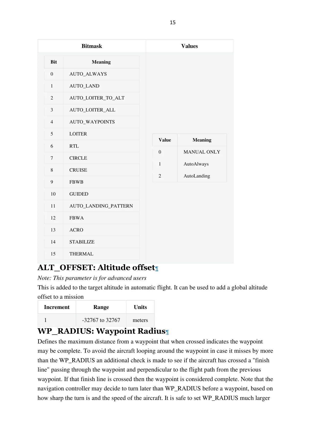
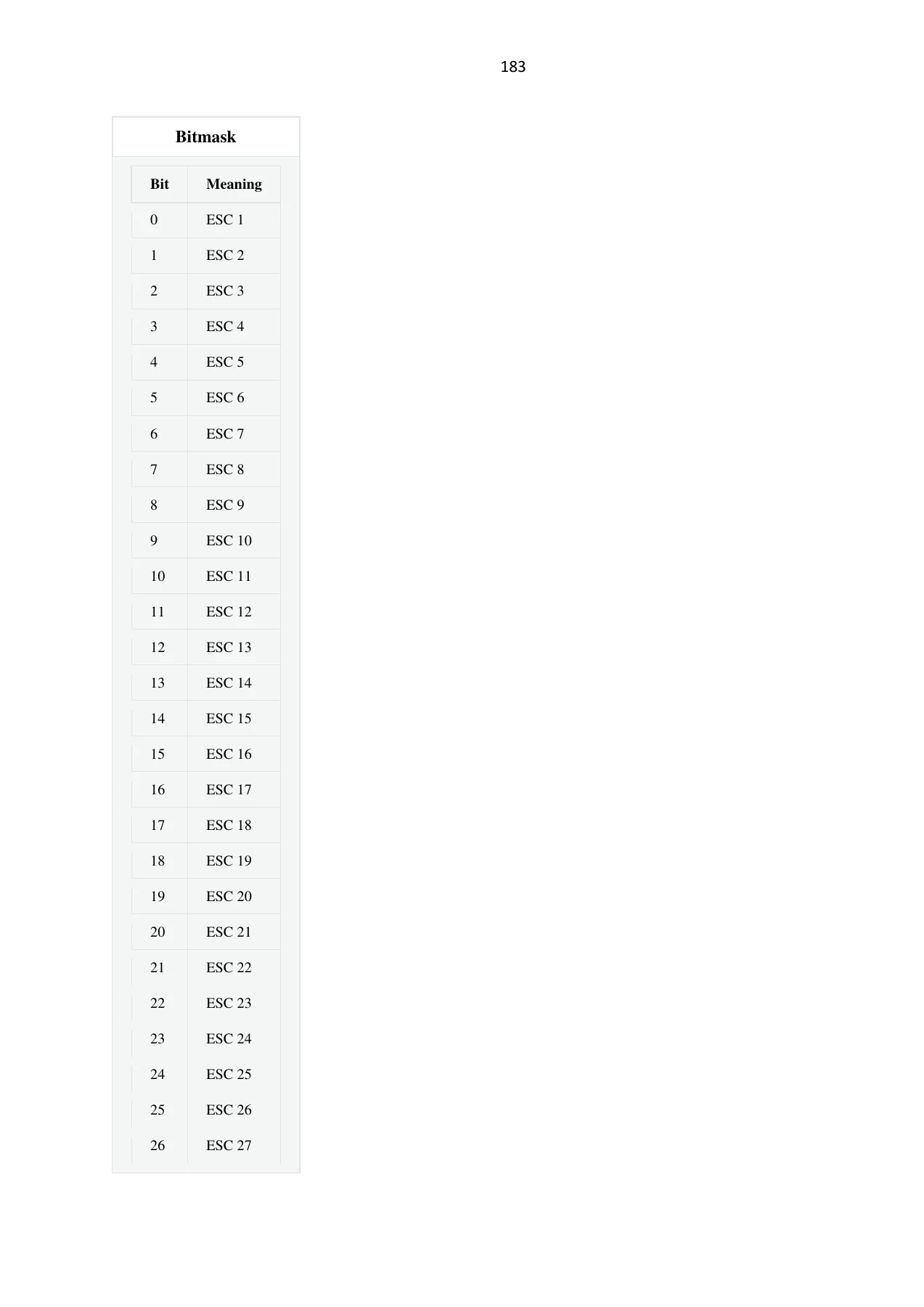
Every entry follows the same predictable layout, which is what makes the list usable in the field. The parameter name appears as a heading, followed by a plain-language description of what the parameter controls. Beneath that comes the constraint block: the accepted range, the increment applied when the value is stepped, the units, and – for enumerated parameters – the full table of values with the meaning of each one. Bitmask parameters list every bit position and what setting that bit enables.
That structure matters because ArduPilot parameters are unforgiving. A wrong bitmask silently enables a feature you did not want. A wrong unit – metres per second versus centimetres per second, centidegrees versus degrees, decisconds versus seconds – produces behaviour that looks like a tuning problem but is actually a configuration error. This list removes that ambiguity by printing the unit alongside the range for every parameter.
Parameters marked as being for advanced users are called out as such, so it is easy to see at a glance which settings are safe to touch during routine setup and which ones alter flight behaviour in ways that need to be understood first. Parameters that require a reboot before they take effect are also flagged, which prevents the common mistake of changing a value, seeing no change in flight, and assuming the parameter does nothing.
Tuning, Safety and Failsafe Parameters in One Place
Because tuning, failsafe behaviour and safety limits are all expressed as parameters in ArduPilot, they all live in this one list. Failsafe short and long actions and timeouts, ground station failsafe enabling, throttle failsafe values, crash detection thresholds, battery low and critical voltage and capacity thresholds with their associated actions, fence type and action, ADSB avoidance behaviour, parachute release criteria, Advanced Failsafe termination pins and conditions, and arming check bitmasks are all documented with their full value tables.
The same applies to the control loop tuning parameters that determine how an aircraft actually flies – the roll, pitch and yaw rate controller gains and filter frequencies, the L1 navigation period and damping, TECS speed and height control gains, and the QuadPlane position, velocity and acceleration controllers. Having the whole tuning surface in one reference means a tuning session does not stall while another document is located.
Who the ArduPilot Plane Complete Parameter List Is For
This parameter reference is aimed at people who configure ArduPilot Plane rather than simply fly it. That includes fixed wing and VTOL builders commissioning a new airframe, integrators setting up a QuadPlane or tailsitter conversion, technicians diagnosing an autopilot that will not arm or will not hold altitude, and developers working against the beta firmware who need the parameter definitions that match the code. It is equally useful to anyone who has inherited an aircraft with a parameter file they did not create and needs to understand what has been changed.
Because it covers beta V4.3.8 specifically, it is the right companion for anyone running that beta release, including the parameters that were introduced or reworked in it and which may not appear in older stable documentation.
Get Instant Access to the Full ArduPilot Plane Beta V4.3.8 Parameter List
With the ArduPilot Plane Complete Parameter List open you can commission, tune and troubleshoot an ArduPilot Plane or QuadPlane autopilot without stopping to hunt for definitions. Look up a parameter and you have its purpose, its accepted range, its units and its complete value or bitmask table on the same page. Configure a VTOL transition, set up a harmonic notch filter, map a serial port, assign a servo output, build an OSD screen layout, or work through a failsafe configuration – the parameters behind each of those tasks are documented in full.
That matters because correct procedures and correct values are what keep an autopilot predictable. Working from the firmware’s own parameter definitions removes the guesswork that leads to a misconfigured bitmask, an inverted unit, or a tuning gain set outside its intended window – the kinds of errors that show up as a loss of control rather than as an obvious mistake. The ArduPilot Plane V4.3.8 parameter list gives you the authoritative values for every setting on the aircraft, in one place, matching the firmware version you are flying.
IMAGES PREVIEW
Delivery is instant. This full ArduPilot Plane beta V4.3.8 parameter reference is supplied as a downloadable PDF the moment your order completes – no shipping, no waiting, no physical media. Read it on a laptop at the bench, on a tablet in the field, or on a phone while you are standing next to the aircraft, and print the parameter groups you need for a build or a tuning session. Buy once and the complete 964-page parameter list stays with you for every airframe you configure on Plane beta V4.3.8.
Reviews
There are no reviews yet.