
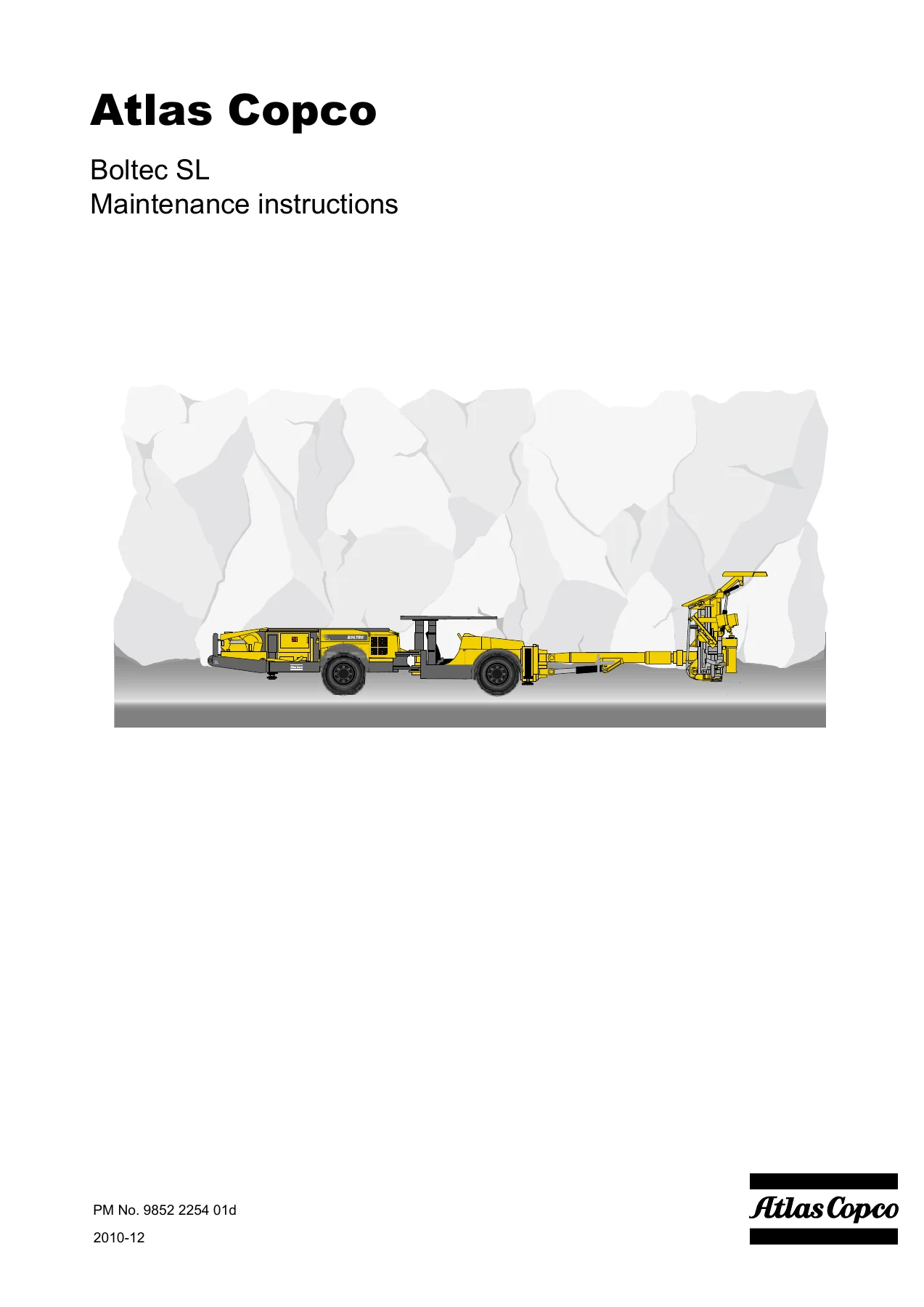
Atlas Copco Boltec SL Maintenance Instructions Manual 9852 2254 01d – PDF Download
Original price was: $39.95.$24.95Current price is: $24.95.
Complete Atlas Copco Boltec SL maintenance instructions (document 9852 2254 01d) covering the BUT 32 LB boom, bolting unit, Deutz TD 2011 L04 engine, transmission, brakes, RCS control system, hydraulics, air and water systems, compressor, electrical system, reeling units and automatic lubrication. Instant PDF download.
Description
Atlas Copco Boltec SL Maintenance Instructions Manual – 9852 2254 01d
This is the full maintenance instructions document for the Atlas Copco Boltec SL rig, published under document number 9852 2254 01d. It is written for mechanics and maintenance personnel who already know the machine, and it walks through every major assembly on the rig: the BUT 32 LB telescopic boom, the bolting unit and feed beam, the Deutz TD 2011 L04 engine, the transmission and drive shafts, the dual-circuit brake system, the RCS control system, the hydraulic circuits, the air and water systems, the LE 7-10 UVB compressor, the IEC electrical system, the reeling units and the automatic lubrication system. Rather than a general overview, this is a hands-on workshop document built around procedures, settings, pressure values, torque figures and wear limits. Once purchased you can download the Atlas Copco Boltec SL maintenance instructions PDF immediately and keep it on any device in the workshop.
File Details
- Manual type: Maintenance instructions
- Brand: Atlas Copco
- Machine: Boltec SL
- Document number: 9852 2254 01d
- Language: English
- File format: PDF
- Page count: approximately 234 pages
Chapters Covered
- 1. General – environment, contact details, target group and objective, record keeping, hydraulic systems, hydraulic workshops, replacement of hydraulic hoses, recommended power supply cable, welding, electrode recommendations, tightening torque in bolted joints, markings and plates, dismantling and assembly, diagnostics, starting with an auxiliary battery
- 2. Lubricants, coolants and propellants – hydraulic oil, lubrication oil, rock drill ECL lubrication system, diesel engine, hydraulic gearbox, wheel axle centre and hub reduction gears, compressor, reeling units, lubrication grease, propellants, capacities
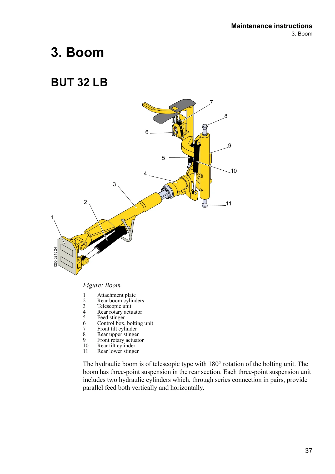
- 3. Boom – BUT 32 LB, starting to use a new boom, technical data, bolted joints and tightening torques, slinging and hoisting, dismantling the boom, expander shafts, boom extension, rotation unit, reconditioning rotary actuators
- 4. Bolting unit – overview, technical data, slinging and hoisting, assembly, check, replacement of the feed chain, slide pieces in holder, slide rails, drill-steel support halves, centring a drill-steel support, retensioning the feed chain, machine cradle on feed beam
- 5. Engine – engine unit Deutz TD 2011 L04, technical data, safety, fuel system, bleeding the fuel system, draining the fuel tank, air system, oil system, belts and tensioning, valve clearance, lifting device
- 6. Transmission – locations, technical data, wheels, steering, drive shafts, transmission, fitting tyres and rims, boom shaft and engine shaft oil levels, hydrostat gear, lubricating the chassis, central lubrication of chassis, towing, adjusting the parking brake
- 7. Brake system – safety, overview, technical data, checking brake pressure, service brake pressure, parking brake pressure, servo pressure on the tramming pump, bleeding the brakes, checking the brake discs, function checks, accumulator charge pressure, brake pressure control valve, scrapping an accumulator
- 8. Control system – RCS, loading new software, save and retrieve parameters, D1 Drilling, D3 Parameters, D4 Statistics, M0 Logging in, M1 System, M2 Logging, M3 Positioning, M4 Drilling, M5 Rig, M6 Bolting unit, M7 Remote control box, M8 Settings, recommended settings
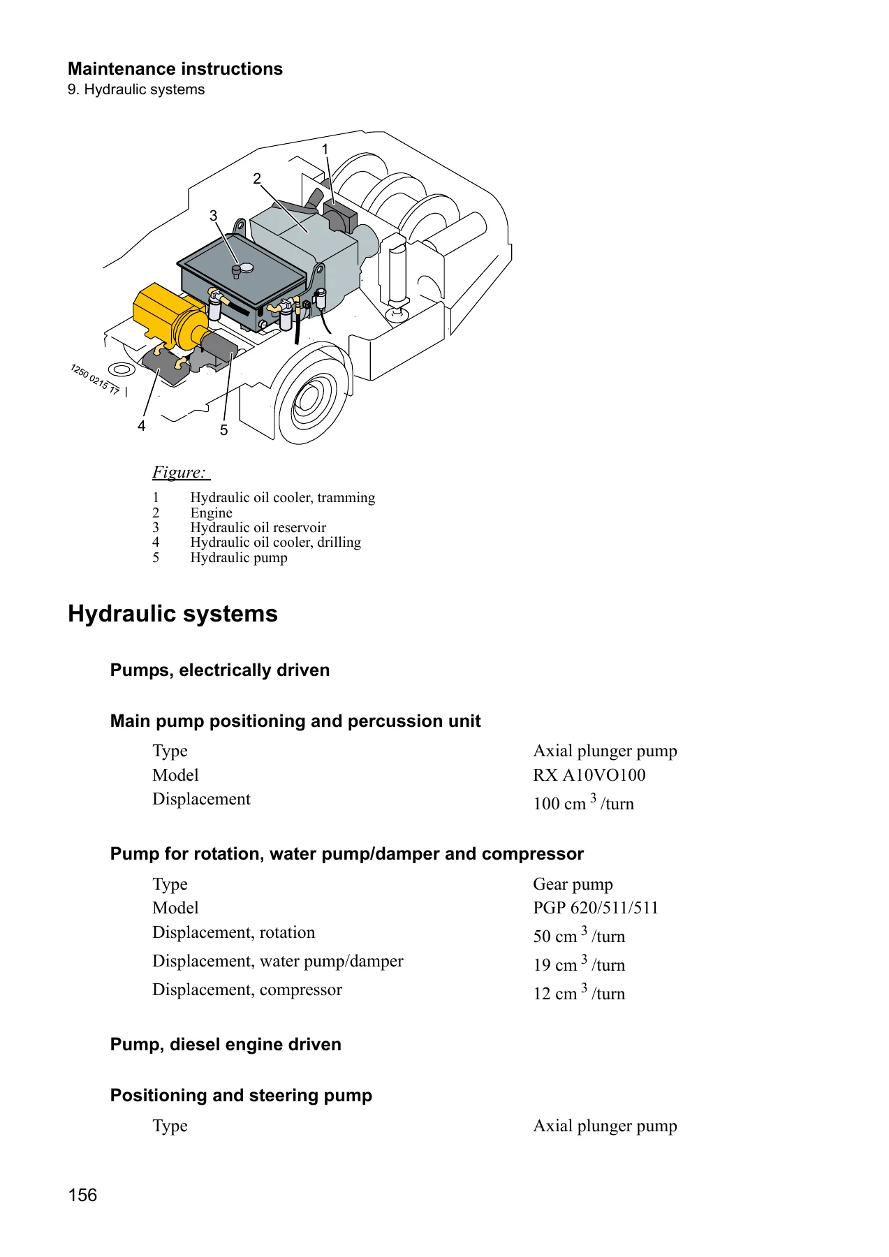
- 9. Hydraulic systems – safety, technical data, overview, return oil filter, breather filter, oil sampling, changing oil, draining condensation, pumps, bleeding and circulating pumps, hydraulic motors, settings, main pump pressure, rotation pump, damper pump, compressor pump, reeling units, oil coolers, pressure sensors
- 10. Air and water systems – safety, recommended hose sizes, water pump, water flow switch, replacing the water pump shaft seal, water cooling the hydraulic oil, cleaning the water strainer, compressor LE 7-10 UVB, pressure sensors and switches, freeze prevention, draining the air tank, ECL lubricating system, lubricant level monitor
- 11. Compressor – safety, compressor instructions, compressor LE 7-10 UVB hydraulic driven, changing air filter, oil level, setting the compressor motor
- 12. Electrical system, IEC – safety, general, safety standard, low-voltage circuit, extra low-voltage circuit, cable marking, replacement of components, electric cabinet high-current, electrical system protection, main switch, overload protection, short circuit protection, phase sequence switch, earth fault equipment, motor protection, cable recommendations, diagnostics
- 13. Component locations – valves, sensors and pressure test outlets on the rig, boom frame, operator’s station, hydraulic pumps and tank, valve plate and engine frame, compressor, engine and transmission, water pump, electrical system, electric cabinets and boxes, RCS system, modules and fuse boxes
- 14. Reeling units – general, reeling unit gear, changing oil, adjusting the reeling unit slip clutch, collector for the cable reeling unit, checking the collector, limit switch option
- 15. Exhaust filtering – safety, catalytic converter, changing the catalytic converter
- 16. Monitoring system, option – interlock circuit, sensors
- 17. Fire fighting equipment – fire fighting systems, Ansul Manual, Ansul Checkfire, central unit, locations, diagnostics, heat detector, safety measures, manual triggering, service, machine maintenance, resetting and fire inspection
- 18. Automatic lubrication – introduction, Lincoln Quicklub 203 lubricating pump, safety valve, setting pause and running time, test function, filling lubrication grease, return connection, power supply, timer terminal, circuit diagram
Across these eighteen chapters the document gives a technician a complete maintenance framework for the Boltec SL. It is not limited to oil changes and filter swaps: it goes into how the boom is slung and split, how the rotary actuators are dismantled and re-timed with their permanent markings, how the feed chain is replaced and retensioned, how the brake accumulators are tested and scrapped safely, and how the RCS menus are navigated to read sensor values, actuate outputs and set parameters. The maintenance instructions also carry the reference data that makes the procedures repeatable – lubricant grades for every compartment, torque tables for the boom bolted joints, pressure settings for the pumps and regulators, and the fluid capacities for the reservoirs on the rig.
Boom, Bolting Unit and Rotary Actuator Work
The boom chapter covers the BUT 32 LB in detail, including what to do when a new or reconditioned boom is first put into service, the retightening routine for bolted joints and expander shafts during the first week, and the complete torque table for the attachment plate, boom links, lift cylinders, stinger feet and rotary actuator mountings. The telescope tube flange joint, the bearing housing bushings, the keys and the slide rails each have their own inspection procedure with wear limits. The bolting unit chapter then handles the feed beam side of the machine – the chain bracket and connecting link, the 381 mm chain position, the slide pieces and slide rails, the drill-steel support halves and the alignment of the cradle on the feed beam.
Engine, Transmission and Brakes
The engine section is built around the Deutz TD 2011 L04 and its BF4L 2011TD ratings, with the fuel filter change, fuel system bleeding, tank draining, air filter indicator, engine oil and filter changes, belt tensioning with a gauge, valve clearance adjustment on a cooled engine, and the correct lifting arrangement. The transmission chapter deals with the Clark Hurth boom and engine shafts, the Rexroth hydrostat gear, hub gear oil levels and changes, chassis lubrication including the central lubrication system, and the full towing procedure with parking brake release and propeller shaft removal. Brake system work is covered with the pressure test outlets, the 60 bar service brake reading, the 25 bar parking brake pressure, accumulator charge pressure testing at 55 bar with a 35 bar minimum, and the four-second limits on the function checks.
RCS Control System, Hydraulics and Air/Water
The RCS chapter is effectively a service menu walkthrough. It shows how to load new software, save and retrieve parameters on a USB stick, and then works through the M-series menus: modules and their status colours, event and statistics logs, positioning sensors and actuations, the drilling feed speed, feed pressure, rotation, timing and threading parameters, damper limits, lubrication settings, rig parameters, bolting unit parameters and remote control lever calibration. The hydraulic chapter backs this up with the pressure test outlet chart, the main pump stand-by pressure of 20-25 bar, the main pump maximum pressure of 210-230 bar, the rotation pump flow setting, the damper pressure of 25 bar, the stinger and feed extension regulator pressures, and the reeling unit pressure and speed limits.
Torque Values, Lubricants and Capacities
Reference values are spread through the document rather than tucked into a single appendix, which is what makes this manual useful at the machine. Lubricant recommendations cover the hydraulic oil viscosity grades against operating temperature, rock drill ECL lubrication oil, diesel engine oil by API and ACEA class, the hydraulic gearbox, wheel axle and hub reduction gears, the compressor, the reeling unit gears, boom and bolting unit grease, contact grease for electrical connections and the diesel fuel specifications. Capacities are listed for the hydraulic oil reservoir, rock drill lubrication oil, engine oil, both hydraulic transmissions, the transmission oil cooler, the compressor, both reeling unit gears and the diesel tank.
Safety, Fire Fighting and Automatic Lubrication
Environmental directions, welding warnings, the rule against welding on the boom, hydraulic workshop requirements and the auxiliary battery starting sequence are all covered in the general chapter. The fire fighting chapter describes the Ansul Manual and Ansul Checkfire systems, the central unit LED and fault codes, the heat detector, the manual triggering procedure and the actions required after a fire or system activation. The automatic lubrication chapter covers the Lincoln Quicklub 203 pump, its safety valve, the pause and running time rotary switches, the test function and the filling procedure.
What This Atlas Copco Boltec SL Maintenance Instructions Manual Gives You
Boltec SL rigs are complex machines with a boom, a bolting unit, an RCS control system and several hydraulic circuits all interacting, and the failure modes are rarely obvious. This Atlas Copco Boltec SL maintenance instructions manual gives you the diagnostic path as well as the repair: the component location chapter tells you which pressure test outlet or sensor designation to look for, the RCS menus tell you what the system is actually reading, and the settings chapters tell you what those readings should be. Instead of guessing whether a pump is weak or a sensor is drifting, you can connect a gauge to the numbered outlet, compare against the specified value, and make the adjustment with the correct screw and lock nut. For the boom and bolting unit, the manual supplies the tightening torques, the expander shaft assembly method, the rotary actuator marking and re-timing procedure, and the chain tension measurement – the details that decide whether a repair lasts or comes back.
Why Correct Procedures and Specs Matter on This Rig
Several procedures in this document exist specifically because doing them wrong causes damage. Welding on the boom can produce thermal cracks and is prohibited. Tightening the expander shaft nut too far can crack the attaching lug. Overfilling the hydraulic tank destroys the breather filter. Setting the park brake bolts without the specified 2 mm back-off or without locking the nuts leaves the brake out of adjustment. Ignoring the 4.5 mm brake disc measurement means running discs past their limit. Loading new RCS software without first saving parameters clears every setting on the machine. The Atlas Copco Boltec SL maintenance instructions manual keeps those warnings and limits in front of you at the moment you need them, along with the torque tables, lubricant grades and capacities that keep the rig running within specification.
IMAGES PREVIEW
Instant PDF Delivery
The manual is delivered as an instant PDF download – no shipping, no waiting for a printed binder, no risk of a missing page. Once payment is complete you can open the file straight away on a laptop, tablet or phone, print the chapters you need for the workshop floor, and keep a permanent copy on the machine or in the service office. If you maintain, service or repair an Atlas Copco Boltec SL, this document is the reference that covers the whole machine from the boom attachment plate to the automatic lubrication timer.
Reviews
There are no reviews yet.