
Atlas Copco DM45 DM50 DML Blasthole Drill Instruction Manual – Safety, Operation & Maintenance
Original price was: $39.95.$24.95Current price is: $24.95.
Complete Atlas Copco instruction manual for DM45, DM50 and DML blasthole drills covering safety, specifications, controls, operating procedures, maintenance schedules, hydraulic and electrical troubleshooting, and glossary. Rev 006, October 2011.
Description
Atlas Copco DM45 DM50 DML Instruction Manual
This is the complete Atlas Copco DM45, DM50 and DML Blasthole Drill Instruction Manual — the same safety, operation and maintenance document used to run and service these mid-range rotary drills in the field. It covers everything from daily walk-around checks and jack levelling to hydraulic pump theory, compressor regulation and engine diagnostics, making it essential reading for operators, mine maintenance crews and field service technicians working on DM45, DM50 or DML rigs.
File Details
- Manual type: Instruction Manual (Safety, Operation and Maintenance)
- Brand: Atlas Copco / Atlas Copco Drilling Solutions
- Models covered: DM45, DM50, DML (Blasthole Drills)
- Language: English
- Page count: 802
- File format: PDF
- Revision: Rev 006 — Last Revision October 2011
- Publisher: Atlas Copco Drilling Solutions, LLC, Garland, Texas
Chapters Covered
- Section 1 – Introduction
- General Information, How this Manual is Organized, Where to Find Information
- Procedure When Receiving the Drill, Identification Data
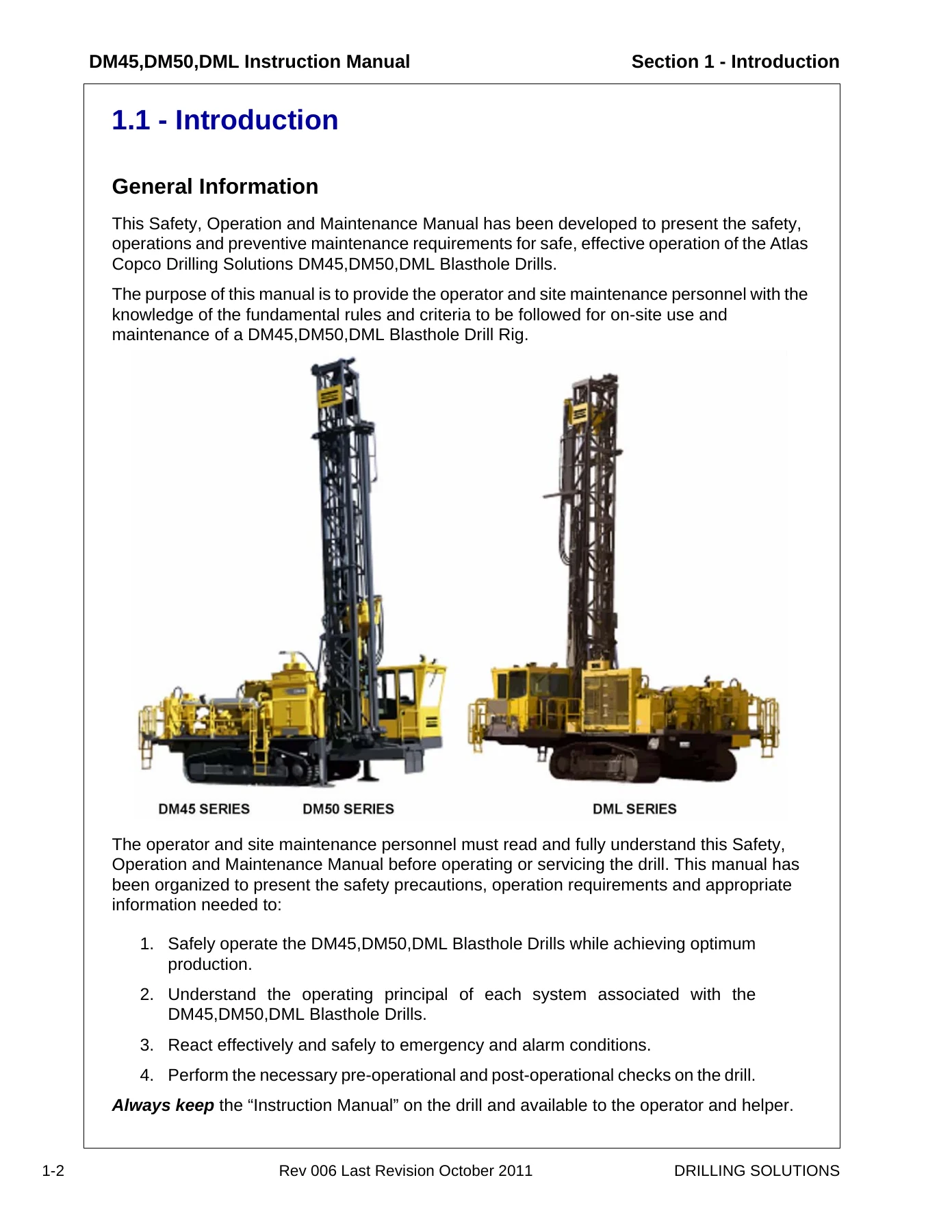
- Drill Description (DM45, DML), Standard Equipment
- Tower, Rotary Head, Feed System, Hydraulic System, Main Frame
- Undercarriage and Propel System, Power Pack, Air Compressor, Engines, Jacks
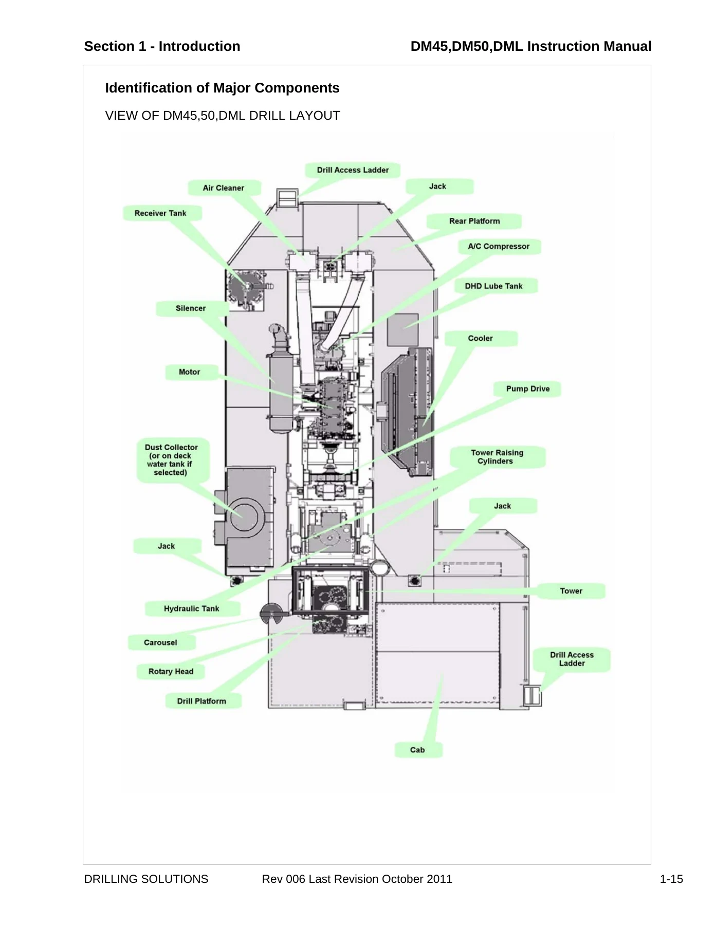
- Operator’s Cab, Lighting, Gradeability, Serviceability, Major Components
- Section 2 – Safety
- Safety and Health, General Safety Statement, Emergencies
- Important Safety Instructions, Safety Precautions and Guidelines
- Designated and Non-Designated Applications
- Electrical Safety, Protection Against Shock, Capacitor Handling
- Pre-Start Inspection, Operation Safety, Setup and Start
- Electrical Power Line Safety, Drilling Safety, Propel (Tram) Safety
- Stopping and Shutdown Safety, Maintenance Safety, Fueling, Batteries
- Wire Rope & Cable, Hot Oil and Components, Cylinder Repairs, Pumps and Motors
- Valves, Hoses, Coolers and Fans, Guards, Tracks, Lubrication, Compressor
- Warning of Special Dangers, Overhead Electric Wires, Ventilation, Grade Limitations, Seat Belts
- Transporting and Towing, Safety Decals and Nameplates
- Section 3 – Specifications
- General Description, Drill Applications, Design Features
- Environment Rate Factor Ranges, Duty, Ambient Temperature, Altitude, Service
- Application Type, Operational Limitations, Stability/Gradeability Charts
- Leveling Limits, Standard Equipment and Specifications
- Main Frame, Leveling Jacks, Undercarriage and Propel System
- Tower, Carousel and Drill Pipe Handling, Rod Capacity Charts
- Rotary Head, Feed System, Power Pack Selection, Air Compressor
- EARS Electronic Air Regulation Control System, Cooler Package
- Hydraulic System, Pumps, Motors, Reservoir, Cylinders, Winch
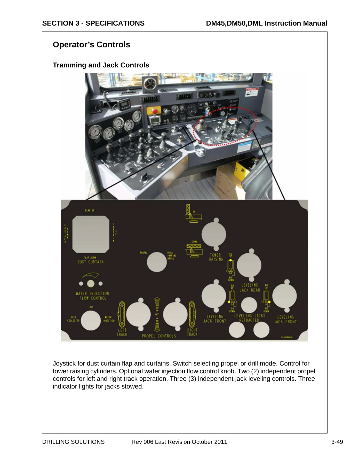
- Operator’s Cab, Seat Belts, Optional Equipment, Controls, Gauges, Air Regulation
- Engine Diagnostic, Heating/AC Controls, Leveling Bubble, DHD Lube Switch, Night Lights
- Optional Equipment — Dust Collector, Water Injection, Angle Drill Package, Strobe Lights, Fire Suppression, Remote Propel, Emergency Shutdown, Central Lubrication, and more
- Dimensions and Weights for DM45, DM50 and DML
- Section 4 – Controls
- Operator’s Console, Drill/Feed Function Panel, Gauges Panel
- Engine Function Panel, Engine Diagnostic Panel
- Compressor Functions Panel, Tram Functions Panel
- Non-Cab Controls — Remote Propel System, Hydraulic Hand Pump, Fan Control, Fire Suppression System
- Section 5 – Operating
- Operating Safety, Seat Belts, Controls and Functions
- Drill/Feed Function Panel — Hoist, Breakout Fork, Carousel Index, Carousel Swing, Chain Wrench, Torque Limit, Rotation, Drill Feed, Air Drill Throttle, Feed Force, Rod Support, Holdback Force
- Compressor Function Panels, Standard and EARS
- Tram Function Panel
- Operating Procedures — Walk Around Inspection, Pre-Start Inspection, Pre-Operation Controls Inspection
- Engine Starting Procedure, Verify Gauges & Controls, Stopping Engine
- Propel, Stopping Drill Propel, Leveling the Drill, Raising/Lowering the Tower
- Tower Pinning (Vertical), Tower Pinning (Angle Drilling Option)
- Over Pressure Control System, Carousel, Setup for Carousel Loading, Carousel Operating Procedure
- Drill Rod Loading, Adding Drill Rod Procedure, Add/Remove Drill Rod From Drill String
- Rotary Drilling — Rotary Drill String Tools and Accessories, Stabilizer Installation, Tricone Bit Installation, Rotary Drilling Procedure, Rotary Bit Changing
- DHD Drilling — Description, Downhole Drill String Tools, DHD Processes, DHD Installation, Button Bit Installation, Installing DHD Hammer to Drill Rod, Starting the Hole with a DHD, DHD Drilling Procedures, Bit Removal, General Drilling Hints
- Transporting the Drill, Loading by Drive On, Loading with Lifting Equipment, Tie Down, Towing, Special Conditions of Use, Preservation & Storage
- Section 6 – Maintenance
- Maintenance Safety, Fluid Penetration, Lines/Tubes/Hoses, Burn Prevention, Coolant, Oils, Batteries, Fire/Explosion Prevention, Fire Extinguisher, Crushing/Cutting Prevention
- Maintenance Schedule Information, Refill Capacities/Lubricants
- Lubrication Table, Refill Capacities, Recommended Oils and Lubricants
- Anti-Freeze, Compressor Oil (Standard/Arctic), Hydraulic Oil (Standard/Arctic), Engine Oil, Gear Oil, Final Drive Oil, Grease, Diesel Fuel
- Maintenance As Required — Clean the Drill, Loose Bolted Connections, Feed Cable & Wire Rope, Feed Cable Replacement, Wire Rope, Winch Wire Rope Installation, Feed Cable/Chain Adjustment, Cable Lubrication, Grease Drum Option, Auto Thread Lube
- Maintenance (8-10 Hours) — Overpressure Control System Test, Engine and Compressor Air Cleaner, Engine Oil/Belts/Tensioner, Engine Fuel Filter/Water Separator, Fuel Tank, Cooling System, Receiver Separator Tank, Compressor Oil Level, Hydraulic Reservoir, Rotary Head, Dust Collector, Manual Lubrication Points
- Maintenance (50 Hours or Weekly) — Batteries, Hoist (Winch), Pump Drive Gearbox, FMC John Bean Water Injection Pump, Undercarriage, Final Drive Mounting Bolts, Final Drive Oil Level, Tracks, Track Tension, Track Adjustment
- Maintenance (100-150 Hours) — Hoist Mounting Bolts, Track Planetary Gearbox, Change Initial Track Planetary Oil
- Maintenance (250 Hours) — Cat Engine Oil and Filters, Cat Engine Fuel and Coolant Filters, Racor Fuel Filter, Engine SCA Level, Engine Valve Lash, Cummins Engine Oil and Filters, Cummins Engine Fuel and Coolant Filters, QSK19 Tier 2 Fuel Filters, Air Cleaners (Engine and Compressor)
- Maintenance (500 Hours) — Hydraulic Oil Analysis, Hydraulic Reservoir, Change Hydraulic Oil, Hydraulic Tank Filling Procedures, Hydraulic Tank Breathers, Pump Drive Gearbox, Feed Cable and Wire Rope, Victaulic Air Hose and Clamps, Hoist (Winch) 8000#, Compressor Change Oil Filters, Tower Feed Cables and Chains
- Maintenance (1000 Hours) — Compressor Oil Analysis, Change Receiver Tank Oil, Hydraulic Oil Filters, Main Return Filters, Case Drain Filter, Rotary Head, Hoist (Winch) 8000#, Rod Changer Reducing Gear
- Maintenance (1500-2000 Hours) — Receiver Tank Separator Element, Compressor Fire Prevention, Track Planetary Gearbox, Water Injection Pump, Air Compressor Discharge Hose
- Maintenance (3000 Hours or 3 Years) — Cat Engine Coolant System, Drain Coolant, Flush Coolant System, Filling Coolant System
- Maintenance (5000 Hours) — Hydraulic Oil Change and Filling Procedures
- Maintenance (6000 Hours or 2 Years) — Cummins Engine Coolant System, Drain Coolant, Flush Coolant System, Filling Coolant System
- Torque Specifications — Standard Torque Values, Recommended Torques in Ft/Lbs, Recommended Torques in Nm, Metric Torque Values
- Section 7 – Systems/Troubleshooting
- Introduction, Safety Precautions, Fluid Penetration, Lines/Tubes/Hoses, Burn Prevention, Coolant, Oils, Batteries, Fire/Explosion Prevention, Engine Starting/Stopping
- Hydraulic Symbols — Fluid Power Symbols, Line Symbols, Crossing/Joining Line, Flexible Line, Arrow, Reservoir/Tank, Fluid Container, Accumulator, Restrictor, Hydraulic Cylinders, Activating Device, Miscellaneous, Pump and Motor, Pump Symbols, Hydraulic Motor, Instrument, Valves, Pressure Relief, Sequence, Pressure Reducing, Directional Control, Two Position Flow Control, Three Position Flow Control, Valve Symbols, Three Position 4-Way Valve, Arrows, Forward/Neutral/Reverse Position, Valve Centers, Series Parallel Valves, Pilot Operated Lock Check Valve, Bypass Valve, Overcenter Valve
- Hydraulic System — Main Pumps, Propel Circuit, Propel Motors, Motor Brake, Diverter Valve, Propel/Drill Mode Selector, Drill/Propel Control Valve, Loop Filling/Replenishment, Loop Flushing Circuit, Circuit Operation, Oil Path Selection
- Feed & Rotation Circuit — Rotation Motors, Rotation Motor Adjustment, Rotation Motor Control Valve, Check Valves, Diverter Valve Assembly, Feed Cylinders, Remote Compensator Control, Over Pressure Control, Regen Valve, Feed Circuit, Load Holding, Holding Valve Circuit, Sequence Valve Circuit (LP Drills), Sequence Valve Circuit (HP Drills), Automatic Holding Selection, Regeneration, Automatic Regen Selection, Removing Excess Oil, Adjustment Procedure, Conversion Procedure, Service Procedure
- Rotation Circuit — Motor Displacement Control, Oil Path Selection, Loop Filling/Replenishment, Torque Limit Control, Drill Feed Pressure, Over-Pressure Control, Troubleshooting Feed System, Vent Feed Control Valve, Leak Checks, Down Feed Pressure
- Auxiliary Functions — Components, Triple Pump, P1/P2/P3 Pump Circuits, Motors, Cylinders, Relief Valves, Restrictor Valves, Check Valves, Two Way Valve, Holding Valves, Pilot Check Valves, 6-Spool Valve, 9-Spool Valve, Circuit Operation, 9-Spool Valve Sections
- Cooling Circuit — Fans, Cooling Package, Fan Motor Relief Valve, Hydraulic Oil Cooler, Filters
- Electric Over Hydraulic System — Overview, General Concepts and Terminology, Current Control, Pulse Width Modulation, Threshold, Maximum Out, Dual Range, Single Coil Controllers, Dual Coil Controllers, Parker/Denison 9A Stroker, Valves, Apitech Pulsars, 6-Spool Valve, 9-Spool Valve, FEMA Pulldown/Torque Limit/Holdback Control Valves, Controllers, Limit Switches, Relays, Typical Coil Resistance, Checking Limit Switch, Checking Diode, Operation, Jack Controllers, Hoist Controller, Tower Raising Controller, Rod Indexer Controller, Breakout Wrench Controller, Carousel Swing Controller, Chain Wrench Controller, Water Injection Controller, Dust Collector, Dust Hood Controller, Tower Pinning, Drill Propel Valve, Drill Feed Circuit, Rotation Control, LP Drill Feed and Rotation Controller, Feed Controller (HP), Drill Feed Force/No Bump Rod Changer, Holdback Control (HP), Rotation Control, Torque Limit Control, EHC Adjustments, Feed and Rotation Controllers, Propel Controller Adjustment, Dust Collector, Dust Collector Troubleshooting, Setting the Electric Timer
- Hydraulic Tank
- Electrical System — Electrical System Information, Cat Engine Panel, Cummins Engine Panel, Starting Engine, Electrical System Components, Batteries, Fusible Links, Alternator, Key Switch, Circuit Breakers, Push Buttons, Tachometer/Magnetic Pickup, Hour Meter, Relays, Diodes, Engine Shutdown Devices, Compressor Discharge Temperature Switch, Engine Water Temperature Switch, Engine Oil Pressure Switch, Engine Speed Switch, Emergency Engine Shutdown, Cat Sensors and Electrical Components, Coolant Temperature Sensor, Coolant Level Sensor, Engine Oil Pressure Sensor, Fuel Temperature Sensor, Fuel Pressure Sensor, Air Inlet Temperature Sensor, Atmospheric Pressure Sensor, Turbocharger Outlet Pressure Sensor, Speed Timing Sensor, Engine Speed Governing, Cat Engine Diagnostics, Self Diagnostics, Diagnostic Lamp, Diagnostic Flash Code Retrieval, Event Codes, Fault Logging, Engine Operation with Active Diagnostic Codes, Engine Operation with Intermittent Diagnostic Codes, Cummins Engine Diagnostics, Engine Protection System, Cummins QSK19 Fault Code Tables, Red Light Fault Codes, Amber Light Fault Codes, White Light Fault Codes
- Pneumatic System — Compressed Air System Overview, Compressed Air System, Introduction, System Operation, Standard Compressor (Non-EARS) System, Operator Observed Problems, Compressor Fire Prevention, Pneumatic System Information, Compressor Oil Lube System, Low Pressure Compressor (Non-EARS), Lubrication System, Separation System, Regulation System, Regulation System Components, Operation of Low Pressure Compressor, Compressor Related Problems, High Pressure Compressor (Non-EARS), Overview, Lubrication System, Separation System, Regulation System – High Pressure, Operation, Air Pressure Regulation, Electronic Air Regulation System (EARS) Compressor System, Introduction, Components, EAR-EFR Diagnostics, Standard Test Conditions, Error Code Meaning, Blown Fuse Check List, Actuator Diagnostic Table, Actuator Test Using An Actuator Test Box, Potentiometer Testing Using A Multi-Meter, Tables, Summed On/Off Inputs Decode Table, Connectors Of Sensor and Actuator, Female Control Connector
- PowerView — Murphy Link PowerView, Description, Faceplate Features and Keypad Functions, Mechanical Installation, Electrical Installation, PowerView Operation, Main Menu Navigation, Engine Configuration Data, Stored Fault Codes, Faults and Warnings, Auxiliary Gauge Fault, Active Fault Codes, Shutdown Codes, Back Light Adjustment, Contrast Adjustment, Select Units, Setup 1-Up Display, 4-Up Display Setup, Utilities, J1939 Parameters
- HNBR Hose / Victaulic Coupling Installation
- Dixon Boss Clamp Installation Instructions
- IC Clamp Installation and Instructions
- Engine Heater (Option) — Introduction, Technical Specifications, Principal of Operation, Normal Operating Sequence, Function and Component Diagnostics, Troubleshooting & Repair, Operational Problems, Maintenance, Heater Wiring Diagram, Timer, Diagnostics
- Centro-matic Lube (Option) — Principle of Operation, Fill Supply Line, Prime Feed Lines, Failures without Alarm Systems, Failures with Alarm Systems
- Bean (FMC) Water Injection Pump — Service Procedures, Replacing Piston Cup Seals, Replacing Suction and Discharge Valves, Replacing the Power End Bearings, Servicing the Wrist Pin Bearings, Fastener Torque Requirements, Troubleshooting Piston Pumps
- Section 8 – Glossary
- Glossary of Terms
- Manual Revisions
Few things on a blast hole drill site are as valuable as a single document that tells the operator how to run the rig properly and tells the maintenance crew how every system is put together. This Atlas Copco instruction manual for the DM45, DM50 and DML does exactly that. It walks through the safety rules first, then the specifications for each model and option, then the controls and operating procedures, then the full maintenance schedule, and finally the hydraulic, electrical and pneumatic system theory with troubleshooting charts. The troubleshooting and systems section alone spans hundreds of pages of hydraulic schematics, electrical diagnostics, compressor regulation theory and engine fault code tables. Whether you are a driller learning the console or a mechanic chasing a hydraulic fault, this manual gives you the diagrams and values to work from.
What This DM45 DM50 DML Instruction Manual Covers In Practice
This is not a thin operator’s leaflet. The document runs 802 pages and covers the complete life cycle of the drill from daily pre-start checks through engine and compressor diagnostics. For the DM45 and DM50, the manual details the 900–1200 CFM low-pressure and 900–1070 CFM high-pressure compressor options, the Caterpillar C15/C18 and Cummins QSX15 engines, the Atlas Copco ACGT2500 and Caterpillar 325L undercarriages, and the standard 30 ft tower. For the DML, it covers the 1200–1900 CFM low-pressure and 1250–1450 CFM high-pressure compressor options, the Caterpillar C15/C18/C27 and Cummins QSX15/QSK19 engines, the ACGT3000 and Caterpillar 330 undercarriages, and both the 30 ft and optional 35 ft towers.
On the operating side, the manual walks through the full engine starting sequence, gauge verification, tramming, jack levelling, tower raising and pinning, carousel loading and rod handling, rotary drilling and DHD drilling procedures, bit changing, and drill transport. On the maintenance side, it lays out service intervals from 8–10 hours through 6000 hours, with fluid capacities, lubricant specifications, torque values in both ft/lbs and Nm, and step-by-step service procedures for the engine, compressor, hydraulic system, rotary head, undercarriage and water injection pump.
Why Correct Procedures and Specifications Matter on These Drills
The DM45, DM50 and DML are production machines. A missed torque value on a final drive mounting bolt, an incorrect hydraulic oil, a wrongly adjusted sequence valve or a compressor shut down under load can lead to component failure, downtime and expensive repairs. This manual gives the exact figures and procedures Atlas Copco published for these drills — from the 420 ± 50 ft/lbs final drive bolt torque and the 1–3/4″ to 1–7/8″ feed cable sag setting to the LP-150 and HP-350 compressor oil requirements, the 65 psi minimum supercharge pressure, and the daily overpressure control system test procedure.
The troubleshooting sections go further than most manuals. The hydraulic symbols chapter teaches you to read the schematics, the feed and rotation circuit chapter explains regeneration and load holding in detail, and the electric over hydraulic section covers the FEMA valves, Apitech Pulsars and Parker/Denison 9A stroker controls used on these rigs. The engine diagnostics chapters for both Caterpillar and Cummins engines list fault codes and their meanings, so you can pull codes and understand what the ECM is reporting before calling for specialist service.
Who This Atlas Copco DM45 DM50 DML Manual Is For
This instruction manual is written for the operator, the site maintenance technician and the field service mechanic working on Atlas Copco DM45, DM50 and DML blasthole drills. Drillers use the controls and operating sections to run the rig correctly. Maintenance crews use the lubrication charts, maintenance schedules and torque tables to keep the machine in service. Mechanics and electricians use the hydraulic, electrical and pneumatic system sections to diagnose faults and perform repairs. Safety officers and trainers use the safety section and safety decal illustrations for site induction and toolbox talks.
If you work on or around these drills, having the manual on hand means you have the manufacturer’s own procedures, specifications and warnings in front of you rather than relying on memory or guesswork.
Get Instant Access to the Atlas Copco DM45 DM50 DML Instruction Manual
IMAGES PREVIEW
This Atlas Copco DM45 DM50 DML Instruction Manual is delivered as an instant PDF download. There is no shipping, no waiting and no physical book to carry around. Once you complete checkout, you can download the file immediately and open it on a laptop, tablet or smartphone in the workshop, the cab or the office. Every page is printable, so you can print the safety decal pages, the torque tables or the troubleshooting flow charts and keep them with the machine. Whether you need the full 802-page manual for reference or just a few key pages for a specific job, the PDF format lets you work the way you need to.

Reviews
There are no reviews yet.