
Audi A8 1994 Onward 3.7 ltr. 4.2 ltr. 5-Valve 8-Cylinder Engine Workshop Manual
Original price was: $39.95.$23.95Current price is: $23.95.
Workshop manual for Audi A8 1994 onward 8-cylinder engine mechanics, covering 3.7 ltr. and 4.2 ltr. 5-valve engines with engine IDs AQF, AQG, ARU, AQH, AUW, AVN, AVP, AKC, AYS, BCS, AKB and AUX. Edition 06.2009 with engine removal and installation, crankshaft and piston work, cylinder heads and valve gear, lubrication, cooling and exhaust-system procedures.
Description
Audi A8 1994 Onward 3.7 ltr. 4.2 ltr. 5-Valve 8-Cylinder Engine Workshop Manual
This Audi A8 engine workshop manual is a focused mechanical repair reference for the Audi A8 1994 ➤ with 3.7 ltr. and 4.2 ltr. 5-valve 8-cylinder engines. It covers engine IDs AQF, AQG, ARU, AQH, AUW, AVN, AVP, AKC, AYS, BCS, AKB and AUX, bringing together removal, dismantling, measurement, checking, installation and adjustment information for the major mechanical engine systems. Edition 06.2009 is arranged by Audi repair groups, so a technician can move from technical data and safety information into engine removal, crankshaft work, cylinder-head and valve-gear repairs, lubrication, cooling and exhaust-system procedures.
File Details
- Manual type: Workshop Manual
- Vehicle: Audi A8 1994 ➤
- Engine coverage: 8-cylinder engine, 3.7 ltr. and 4.2 ltr. 5-valve, mechanics
- Engine IDs: AQF, AQG, ARU, AQH, AUW, AVN, AVP, AKC, AYS, BCS, AKB, AUX
- Edition: 06.2009
- Language: English
- Page count: 167 pages
- File format: PDF
- Document reference: A0050808420
Mechanical Engine Coverage
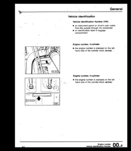
The Audi A8 1994 Onward 3.7 ltr. 4.2 ltr. 5-Valve 8-Cylinder Engine Workshop Manual goes well beyond routine maintenance. The technical-data section identifies the engine number location and gives engine data for the covered code letters, including capacity, power output, torque, bore, stroke, compression ratio, fuel requirements and engine-management features. General repair guidance addresses cleanliness, leak checks, foreign-particle control, contact corrosion, correct routing of pipes and wiring, vacuum-system checks and precautions for cooling and exhaust work.
Major engine work is covered step by step. The engine removal section explains removal of the engine together with the gearbox from the front, separation of engine and gearbox, attachment to an engine stand and installation. It identifies workshop equipment and provides tightening data for the engine and gearbox connections and related components. This makes the manual useful when work has progressed beyond in-car servicing and the power unit must be removed for access or overhaul.
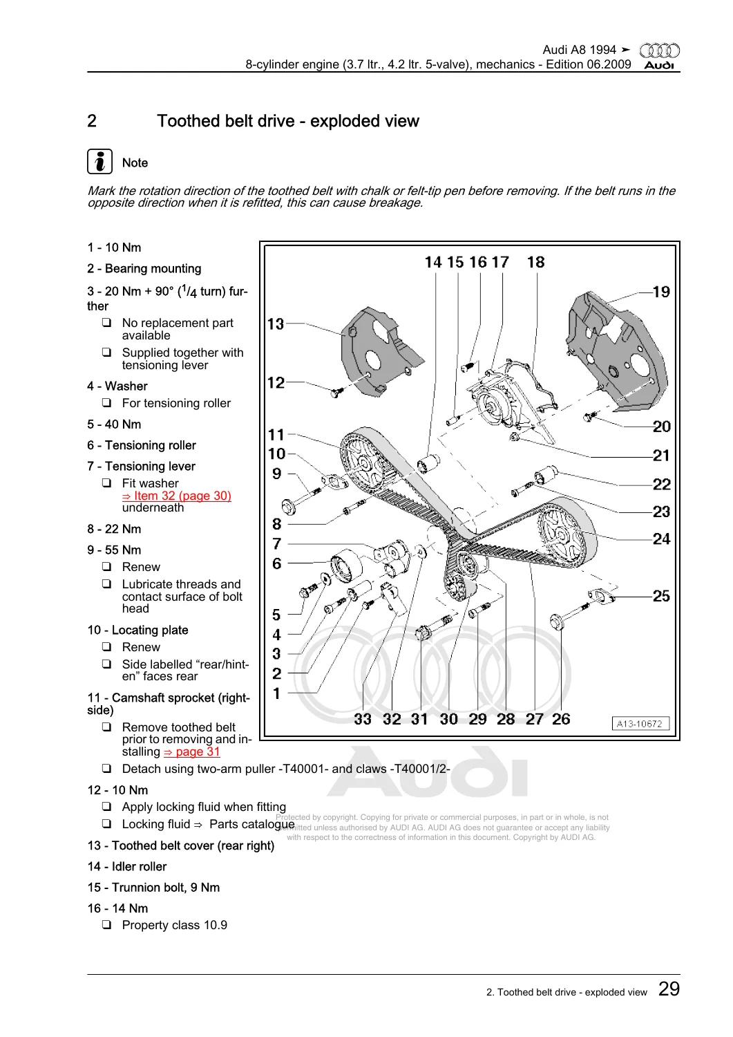
The crankshaft group contains illustrated exploded views and service procedures for the poly V-belt drive, toothed belt drive, vibration damper, sealing flanges, drive plate, crankshaft, pistons and conrods. Timing-belt work includes the locking and clamping tools, TDC positioning, camshaft-sprocket handling, belt tensioning and timing checks. Internal-engine measurement sections include crankshaft journal dimensions, axial and radial clearances, piston-ring gaps, ring-to-groove clearance, piston and cylinder dimensions and conrod-bearing clearance. The manual therefore supports both component replacement and measurement-based inspection against printed limits.
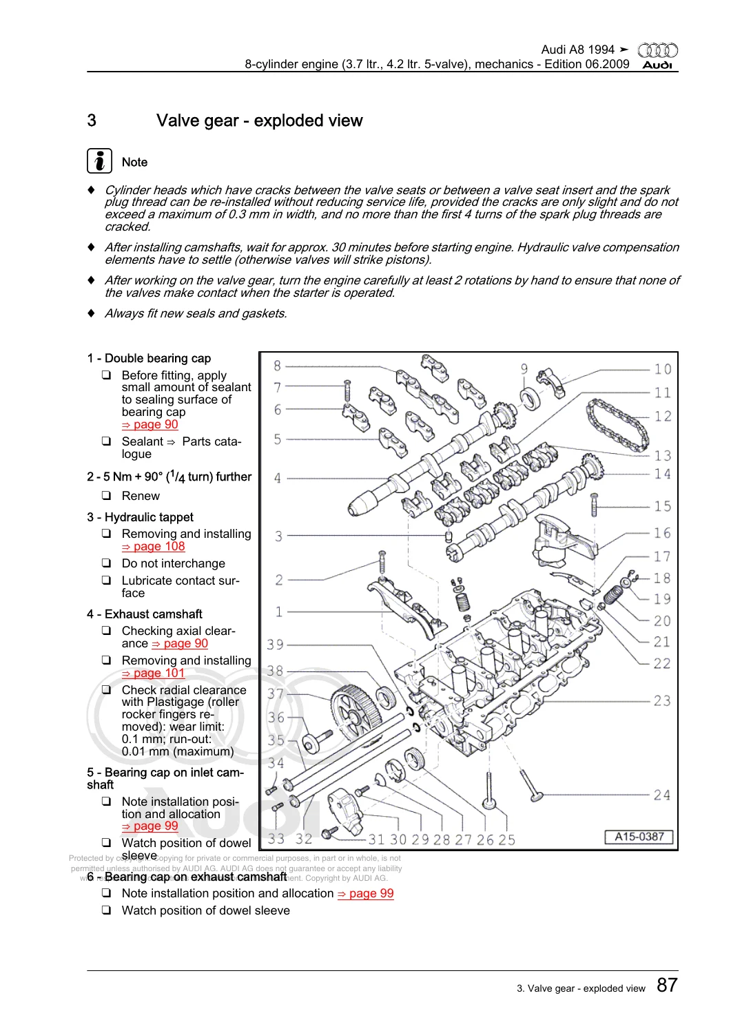
Cylinder-head and valve-gear work is similarly detailed. Procedures cover left- and right-side cylinder-head covers, cylinder-head removal and installation, compression testing, camshafts, camshaft adjusters, roller rocker fingers, valve stem oil seals, valve guides, valves and valve-seat machining. The manual specifies fitting sequences, special tools, tightening stages and inspection values where required. Its compression-test procedure also gives test conditions and pressure limits, helping distinguish a simple check from the more extensive mechanical work that may follow.
Lubrication and cooling sections add practical diagnostic and repair coverage. The lubrication group includes the oil pump, both sump sections, oil-pump chain drive, oil level and oil temperature sender G266, oil retention valves, oil filter housing, oil-pressure switch F1, engine-oil checks and oil-pressure testing. Cooling coverage includes the coolant-hose layout, draining and filling, coolant pump, thermostat, leak testing, expansion-tank pressure-relief valve, oil cooler, viscous fan, radiator and radiator fan V7. The exhaust group completes the mechanical scope with silencer and mounting layouts, exhaust manifolds, left- and right-side front exhaust pipes with catalytic converters, stress-free alignment and leak checking.
Chapters Covered
- 00 – Technical data
- Technical data: engine number and engine data
- Safety precautions: cooling system, road-test measuring equipment and exhaust system
- General repair instructions: cleanliness, fuel-system leak checks, foreign particles, contact corrosion, pipe/hose/wiring routing, vacuum system and heat-exchanger installation guidance
- 10 – Removing and installing engine
- Removing and installing engine
- Separating engine and gearbox
- Attaching engine to engine stand
- Installing
- 13 – Crankshaft group
- Poly V-belt drive – exploded view, belt removal/installation, alignment and vibration damper
- Toothed belt drive – exploded view, removal/installation and removal from camshaft sprockets
- Sealing flanges and drive plate – exploded view, crankshaft oil seal, front/rear sealing flanges and drive plate
- Crankshaft – exploded view, dimensions, axial/radial clearance and oil-pump drive chain sprocket
- Pistons and conrods – exploded view, piston/cylinder dimensions and conrod-bearing radial clearance
- 15 – Cylinder head, valve gear
- Removing and installing cylinder head, including both cylinder-head covers and left/right cylinder heads
- Checking compression
- Valve gear – exploded view
- Camshaft axial clearance and camshaft oil seals
- Hall sender oil seal
- Camshafts and camshaft adjuster for left- and right-side cylinder heads
- Roller rocker fingers and valve stem oil seals
- Valve guides, valves and machining valve seats
- 17 – Lubrication
- Oil pump and sump (bottom section) – exploded view
- Oil level and oil temperature sender G266
- Bottom and top sump removal/installation
- Oil-pump chain drive and oil pump
- Oil retention valves and oil filter housing
- Oil pressure and oil pressure switch F1 checks
- Engine oil and oil-level checking
- 19 – Cooling
- Diagram of coolant hose connections
- Draining and filling cooling system
- Coolant pump and thermostat – exploded view
- Coolant pump and thermostat removal, installation and checks
- Cooling-system leak test and filler-cap pressure-relief valve check
- Oil cooler, viscous fan, radiator and radiator fan V7
- 26 – Exhaust system
- Removing and installing parts of exhaust system
- Silencers with mountings – exploded view
- Exhaust manifold
- Front exhaust pipes with catalytic converters, left and right sides
- Stress-free alignment of exhaust system
- Checking exhaust system for leaks
Across these repair groups, the manual combines procedure text with component illustrations, exploded views, tool references, tightening torques, service limits and checking methods. The result is a mechanical-engine reference suited to jobs ranging from belt and seal replacement to cylinder-head work, crankshaft and piston inspection, lubrication-system diagnosis, cooling-system repair and exhaust-system removal and alignment.
Illustrated Procedures, Special Tools and Measured Checks
Many operations are accompanied by drawings that show component location, dismantling order or tool placement. Special tools are identified by their printed tool numbers, including locking pins, camshaft clamps, pullers, seal extractors, fitting sleeves, dial-gauge fixtures, cooling-system equipment and pressure testers. That detail is especially useful on timing, camshaft and sealing work where position, sequence and correct setup matter as much as the replacement part itself.
The manual also gives concrete checks rather than relying only on visual inspection. Examples include crankshaft and conrod bearing clearances, piston and cylinder measurements, valve-guide wear, camshaft clearance, compression pressure, oil pressure, thermostat operation and cooling-system pressure testing. Tightening values appear throughout the relevant procedures and exploded views, allowing work to be completed using the stated fastener requirements instead of relying on memory or generic values.
Repair the Audi A8 3.7 ltr. and 4.2 ltr. 5-Valve Engine with the Correct Reference
The Audi A8 1994 Onward 3.7 ltr. 4.2 ltr. 5-Valve 8-Cylinder Engine Workshop Manual gives you the procedures, illustrations, tightening data, special-tool references and service measurements needed for substantial engine mechanical work on the listed engine IDs. Whether the job involves engine removal, timing-belt setup, crankshaft or piston inspection, cylinder-head and valve-gear repairs, oil-pressure diagnosis, coolant-system work or exhaust-system servicing, having the correct procedure and specification at hand helps reduce assembly errors and supports accurate diagnosis. Your manual is delivered instantly as a PDF after purchase, with no shipping wait; it can be viewed on compatible phones, tablets and computers and printed when a paper workshop copy is useful.
Reviews
There are no reviews yet.