
Barrett RCOS(N)-1 Order Picker Electric Control Manual – Traction & Lift Troubleshooting PDF
Original price was: $34.95.$21.95Current price is: $21.95.
Complete electric control service manual for the Barrett RCOS(N)-1 order picker, covering Curtis PMC traction and lift controllers, speed cut-out relays, plug braking, battery indication, wiring schematics and step-by-step troubleshooting flow charts.
Description
File Details
- Manual type: Electric control maintenance and service manual
- Brand: Barrett Industrial Trucks / Nissan Forklift Corporation North America (NFCNA)
- Model covered: RCOS(N)-1 order picker
- Systems: Traction control, lift and lower control, battery indication
- Language: English
- Page count: 158
- File format: PDF
- Included material: 1995 service bulletins, basic electrical theory, PMC controller service guide, troubleshooting flow charts, full wiring schematics
Chapters Covered
- Service bulletin – RCOS(N)-1 travel lift/lower handle assembly (Part #43607-000): lever binding, cam radius inspection, actuator lever replacement
- Service bulletin – RCOS(N)-1 magnetic sensor strips: handling, repositioning and authorization requirements
- Basic Electrical Theory: voltage, ampere, watt, ohms, polarity, direct current and alternating current
- Commonly used electrical terms: anode, cathode, diode, gate, heat sink, module, oscillator, potentiometer, pulse width modulation, SCR, transistor, P.M.C.
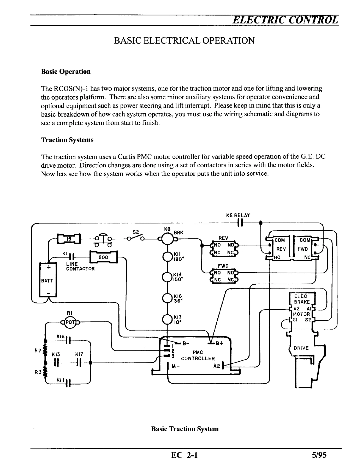
- Basic Operation: traction system and lift/lower system breakdown
- Traction Systems: Curtis PMC motor controller, line contactor K-1, negative relay K-2, brake relay K-6, forward and reverse contactors
- Speed cut-out relays and sensors: 36-inch speed reduction, 150-inch speed reduction, 180-inch travel cut-out, 10-degree steering angle cut-out
- Travel speed chart by fork height, aisle guidance and steering angle
- Plugging (controlled reversing) and plugging distance
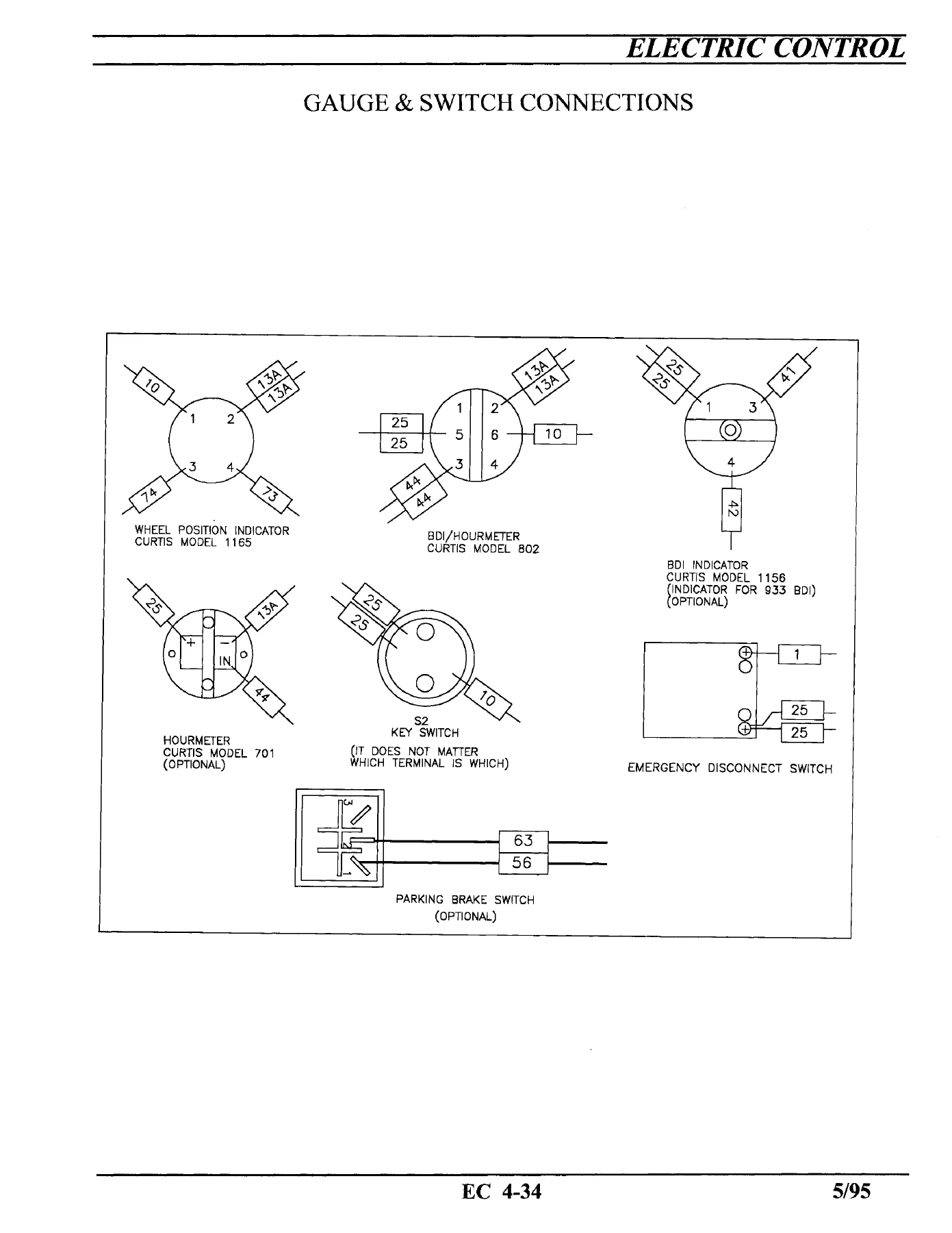
- Steer wheel position indicator and drive wheel indicator potentiometer
- Optional equipment: platform brake switch mat and brake switch strip
- Basic Operation for Lift & Lower: thumb lever, potentiometer, logic unit, PMC lift controller, hydraulic pump motor, hydraulic valve body
- Sensor switches: start switch, loose chain switch, 12-inch maximum height switch, 12-inch lower switch
- Service Guide for PMC Control (1204 / 1205 / 1209B)
- Smooth stepless operation, current multiplication, current limiting, under-voltage cutback, over-voltage protection
- Plug braking, thermal protection, accelerator potentiometer fault protection, high pedal protection, acceleration ramping, weather protection, serviceability
- Controller functional description: power section, logic section, pulse width modulator, current limit comparator, plug detect, limit integrator
- Maintenance and adjustment: controller cleaning, terminal inspection, adjustment potentiometer locations
- Troubleshooting: symptoms and cures, inability to plug brake on a steep ramp, in-vehicle troubleshooting
- Service tips: jumper test at controller terminals 2 and 3, power checks, contactor operation and key switch input, potentiometer circuitry, controller output checks
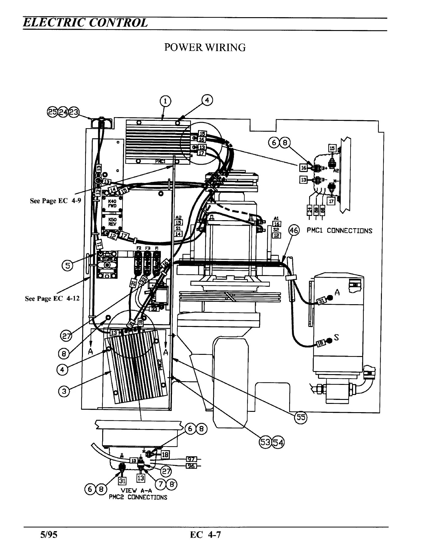
- Electrical schematic and wiring: connector numbering, terminal strips, relay and contactor contacts, switch contacts
- Legend: contactors and relays, fuses, lights, switches, resistors and potentiometers, terminal strips, printed circuit boards, solenoid valves
- EV-100 contactors: contact tip inspection, coil testing, suppressor testing, spiral return spring and contact spring inspection, component replacement
- Curtis 933/3 battery controller: operation, adjustment, reset and discharge potentiometers, troubleshooting, Model 1142 Tester and Model 1141 FasTesT Accessory
- Volt-Ohm-Milliammeter instructions: DC voltage, DC current and resistance measurement
- Handyman component tester instructions: SCR firing and holding tests, blocking and reverse leakage tests, diode forward conduction, capacitor leakage and capacitance, insulation resistance, zener and suppressor tests
- Ground test and troubleshooting do’s and don’ts
This is not a general forklift overview. The Barrett RCOS(N)-1 electric control manual works through the order picker one circuit at a time, starting from the battery and line contactor and following the current all the way to the traction motor, the hydraulic pump motor and the lowering solenoid valves. It explains why the truck slows down when the mast is raised past a certain height or when the steering wheel is turned beyond ten degrees, how the PMC controller switches the motor field through forward and reverse contactors, and how the internal logic card reads a 10 volt signal from the main accelerator potentiometer and turns it into a speed command. The lift and lower half of the book is equally specific, describing how the thumb lever on the multifunction control handle signals the logic unit, when the pump motor runs, and how the number of lowering valves opened determines how fast the platform descends.
Because the control system on these trucks is electronic rather than mechanical, the diagnostic material matters as much as the description. Two full troubleshooting flow charts walk through the two failures technicians see most often: no forward or reverse contactor operation while lift, lower and horn still work, and no travel even though the forward and reverse contactors are closing. Each branch tells you what to measure, where to measure it, and what a good reading looks like, from the brake pedal switch and wire #2 through the speed limit resistors R-6, R-8, R-9, R-10 and R-11 to the 10 degree sensor and the 150-inch and 180-inch switches. The controller itself is covered with the same precision, including how to confirm a bad unit with a jumper between terminals 2 and 3, how to measure controller output between B+ and M-, and how to test the internal plug diode with an ohmmeter at the A2 terminal.
Supporting material rounds out the package. The basic electrical theory section lays out voltage, current, resistance and Ohm’s Law in plain language before the circuit descriptions begin, and the glossary explains the semiconductor vocabulary that shows up throughout the PMC guide. The schematic and wiring chapter defines the connector and terminal numbering convention used on every harness in the truck, lists the fuses, switches, resistors and solenoid valves by designation, and reproduces the power wiring layout, control wiring and mast cable routing for two-stage and three-stage masts. Contactors are treated as serviceable hardware with spring free-length limits, coil resistance ranges and suppressor test values, and the battery controller chapter covers the Curtis 933/3 fuel gauge, lift lockout, reset potentiometer and discharge potentiometer settings in volts per cell.
What This Manual Enables You to Do
The material here supports real repairs rather than guesses. You can trace a no-travel complaint from the brake switch to the contactor coil, verify a potentiometer at 5000 ohms in neutral and 0 ohms at full speed, adjust the acceleration ramp and current limit trimpots on a 1204, 1205 or 1209 controller, set the battery controller reset level, and work out whether a fault lives in the controller, the harness, the motor or the reversing switch before any part is ordered. The service bulletins at the front give you the correct fix for a binding lift/lower lever and the correct procedure for handling mast-mounted magnetic sensor strips.
Correct procedures and correct values are what separate a quick fix from a repeat failure. The troubleshooting sequence in this manual is written in a fixed order for a reason, and following it prevents the misdiagnosis that costs controllers, contactors and downtime. Whether you are maintaining a fleet of RCOS(N)-1 order pickers or bringing a single machine back into service, having the wiring layout, the speed cut-out logic and the controller test points in front of you shortens the job considerably.
IMAGES PREVIEW
Instant PDF Delivery
This Barrett RCOS(N)-1 order picker electric control manual is delivered as a PDF immediately after payment. There is no shipping, no waiting and no physical book to keep track of. Open it on a laptop or tablet in the shop, print the flow charts and schematics you need for the job at hand, and keep the full document on hand for the next fault. The traction and lift troubleshooting sections, the wiring schematics and the controller adjustment procedures are all here in one file.
Reviews
There are no reviews yet.