
Beijing KND K100Ti-D CNC System User Manual – Lathe Programming, Operation and Connection Guide
Original price was: $34.95.$21.95Current price is: $21.95.
281-page PDF user’s manual for the KND K100Ti-D two-axis CNC system, covering programming, operation, tool setting, connection, parameters and alarms.
Description
File Details
- Manual type: CNC system user’s manual
- Brand: Beijing KND CNC Technique Co., Ltd.
- Model: K100Ti-D CNC System
- Document number: B05B-T00N-1101
- Language: English
- Page count: 281
- File format: PDF
- Print date: Jul. 2009
The Beijing KND K100Ti-D CNC System User Manual is a workshop reference for the K100Ti-D control used on lathes and two-axis economical machines. It addresses programming, operation, tool setting, machine connection, parameter descriptions and alarm information. The document states that it applies to K100Ti-D series systems with main board 00201-0100-W01Z-0101 and software version K100Ti-D A01_090428.
This K100Ti-D CNC system user manual is written for practical use: it explains the coordinate system, G-code programming, feed and spindle functions, tool compensation, manual and automatic operation, MDI work, program storage, flash memory handling, RS232 and U-disk transfer, graphics, safety operation, and machine interface wiring. It also notes that some functions are optional and that the machine builder’s panel instructions and operation manual should be consulted where applicable.
Chapters Covered
- 1 General: Introduction on K100Ti-D CNC System; System Specification Table; Statements; Precautions
- 2 Programming: Coordinate System; Program Components; Preparatory Function (G Code); Feed Function (F Code); Miscellaneous Function (M Code); Spindle Functions (S Code); Tool Functions (T Code); Synthetic Program Example
- 3 Operation: General; Operation and Display; Manual Operation; Automatic Operation; MDI Operation; Controlling Feed Rate by Handwheel; Homing Operation; Program Storage and Edit; Flash Memory; Graphics Function; RS232 Communication; Disk Operation; Safety Operation
- 4 Part Machining: Setting the Coordinate System; Setting the Origin of the Machine Coordinate System; Setting the Machine Coordinate System (Tool-Setting Way)
- 5 Connection: System Structure and Installation; System Internal Connection and Setting; System External Connection; Machine Interface
- Appendix A: Memorial Pitch Error Compensation Function
- Appendix B: Parameter Description
- Appendix C: List of CNC Status Diagnosis Messages
- Appendix D: Alarm List
For a technician, the value of this K100Ti-D CNC system user manual is the way it links the programming language to the physical lathe control. It shows how absolute and incremental coordinates work, how G00 and G01 movements are commanded, how circular interpolation, dwell, reference-point return and work coordinate setting are written, and how thread cutting and canned cycles are structured. The operation section then ties those commands to the panel: mode selection, manual feed, handwheel and step feed, spindle control, automatic run, MDI execution, program search and editing, and alarm handling. The connection and parameter sections give the maintenance side of the same system: internal and external cabling, spindle encoder and handwheel interfaces, analog spindle connection, RS232 wiring, I/O signal checks, pitch error compensation and parameter descriptions.
Programming Coverage in the K100Ti-D Manual
The programming portion is broad enough for both day-to-day turning work and more complex cycles. It covers coordinate system setting, program format and block structure, main programs and subprograms, optional block skip, and the preparatory G-code list. Individual command sections include positioning with G00, linear interpolation with G01, circular interpolation with G02 and G03, dwell with G04, automatic return to reference point with G28, work coordinate system setting with G50, thread cutting with G32, thread cutting cycles G92, G76 and G78, cylindrical or taper cutting cycle G90, facing cycle G94, canned tapping cycle G93, multiple repetitive cycles G71 through G75, finishing cycle G70, constant surface speed control with G96 and G97, per-minute and per-revolution feed with G98 and G99, tool nose radius compensation with G40 through G42, offset input by program with G10, skip function G31, and work coordinate systems G54 through G59.
The manual also explains feed and speed functions, M-code functions, spindle functions, tool change and tool offset, tool nose radius compensation with imaginary tool nose directions, and a synthetic program example. That combination makes the K100Ti-D CNC system user manual useful not only as a command list but as a guide to how the control expects a lathe program to be organized, how tool offsets affect the coordinate system, and how cycle paths are interpreted.
Operation, Tool Setting and Daily Use
On the operation side, this K100Ti-D CNC system user manual describes the display and keyboard areas, the operating modes, brightness adjustment, position screens, program screens, tool compensation and measurement screens, parameter screens, diagnosis screens, alarm screens, graph screens and test screens. It explains manual continuous feed, step feed, handwheel feed, spindle feed, manual tool change, coolant control and rate adjustment. Automatic operation is covered from program selection and start through stop, pause, feed hold, block restart, feed override and spindle override. MDI operation, handwheel-controlled feed rate, program homing and mechanical homing are also addressed.
For setting up a lathe, the part machining chapter is especially practical. It explains setting the coordinate system, setting the origin of the machine coordinate system, absolute tool setting, relative tool setting, and adjusting tool offsets. The manual describes using the measurement page, entering tool offset values, and making incremental offset corrections after trial cuts. That material is supported by the later sections on tool compensation values, imaginary tool nose direction, tool nose radius compensation, and tool change timing parameters.
Connection, Parameters and Maintenance Reference
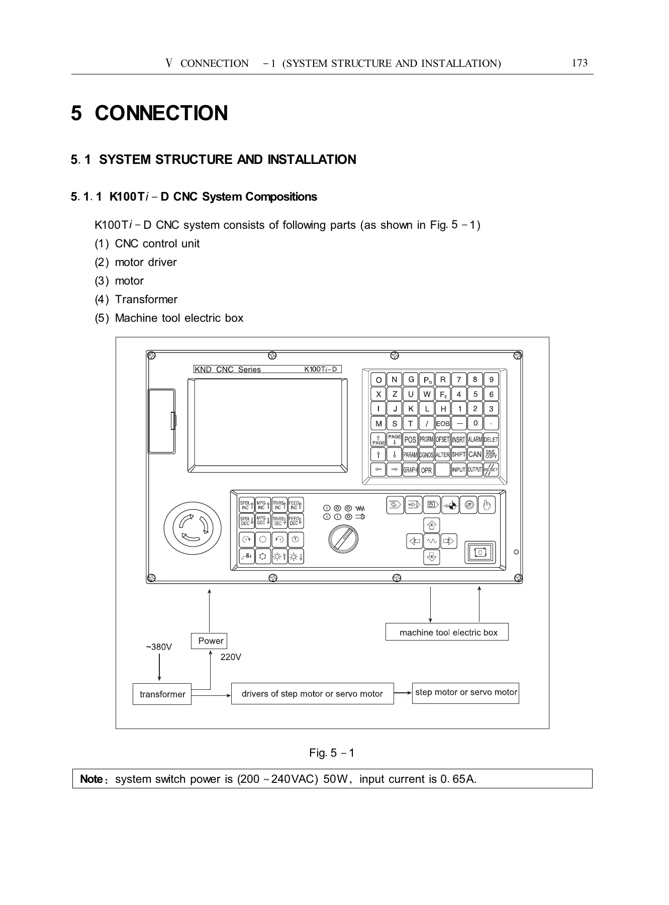
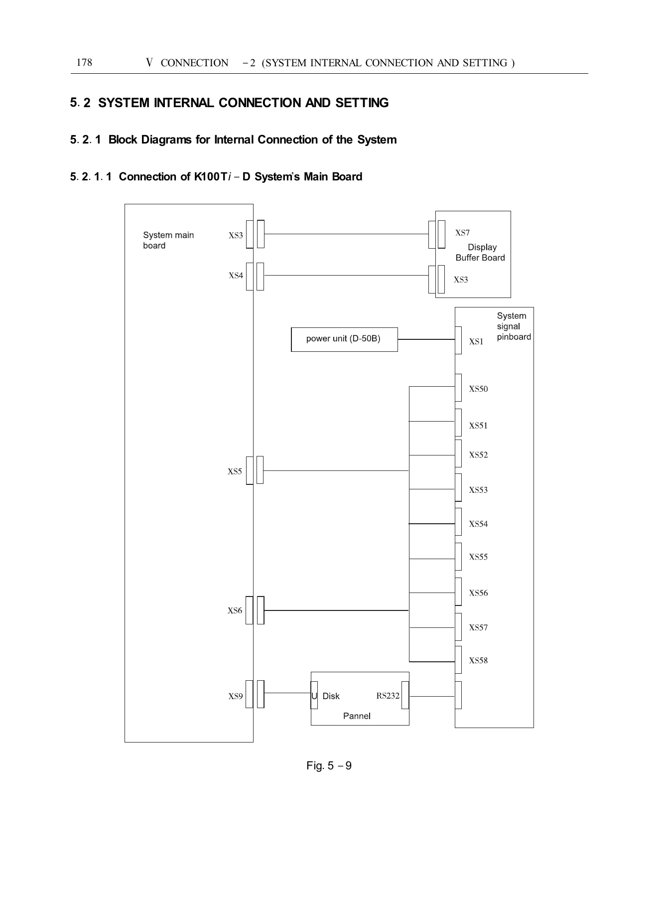
The connection chapter moves from system structure and installation dimensions into internal board connections, panel switch connections, main-board setting switches, rear-cover sockets and external connection diagrams. It covers step motor and digital AC servomotor connection examples, signal lists between CNC and driver, spindle position encoder interface, handwheel interface, analog spindle interface, RS232C communication interface, additional operator panel connection, isolating transformer connection, machine interface input and output circuits, I/O signal diagnosis lists and signal remarks. The appendices add pitch error compensation, parameter descriptions in sequence, functional descriptions for system alarm, homing, communication, spindle, thread cutting, machine tool connection, tool change, chuck and tailstock, handwheel, X/Z axis control, M code, program skip, program edit, system setting, protective door and pitch error compensation, plus diagnosis messages and alarm lists.
Because the manual includes both programming and electrical connection material, it can serve as a single reference point for the K100Ti-D control when a machine is being set up, when a program needs to be proved out, when tool offsets are being adjusted, or when a wiring or parameter question arises. It is not limited to one subsystem; it follows the control from the part program through the operator panel to the machine interface.
Workshop Value and Delivery
With this Beijing KND K100Ti-D CNC System User Manual, a technician can prepare and check lathe programs, understand the available canned and multiple repetitive cycles, set work coordinates and tool offsets, run the machine in manual, MDI or automatic mode, transfer programs and parameters, and refer to connection and alarm information when troubleshooting. The manual supports correct procedure and specification use rather than trial-and-error, which matters when tool offsets, thread cutting, reference-point return or machine interface signals are involved.
IMAGES PREVIEW
The file is delivered as an instant PDF download after payment, with no shipping and no physical media. It can be viewed on a workshop computer, laptop, tablet or phone and printed for bench or control-panel reference.
Reviews
There are no reviews yet.