
★ TRUSTED BY 321,897+ PROFESSIONALS WORLDWIDE
🏒
Trusted Business
Verified & Licensed
πŸ›‘οΈ
Virus Free Files
100% Safe Downloads
πŸ”’
Secure Payment
SSL Protected
⚑
Instant Delivery
Available Immediately
Sale!

Bell B18D-B30D Small ADT Mk VI Service Manual Rev 3 PDF

Original price was: $44.95.Current price is: $27.95.

Comprehensive Bell Small ADT Mk VI service manual for B18D 6X4, B180D 6X4, B20D 6X4, B20D 6X6, B25D 6X6 and B30D 6X6 articulated dump trucks. Covers operational checks, OM 906 LA engine diagnosis and testing, extensive electrical schematics and fault codes, ZF 6 HP 592 C PLUS transmission, pneumatic and hydraulic systems, HVAC, scheduled servicing, lubrication, storage and troubleshooting.

⚑
Instant PDF Download
Available immediately
πŸ’Ύ
Save to Your Device
Download & keep forever
πŸ›‘οΈ
Antivirus Scanned
100% virus-free
🌍
Trusted Worldwide
175,000+ customers

Description

Bell B18D-B30D Small ADT Mk VI Service Manual Rev 3 PDF

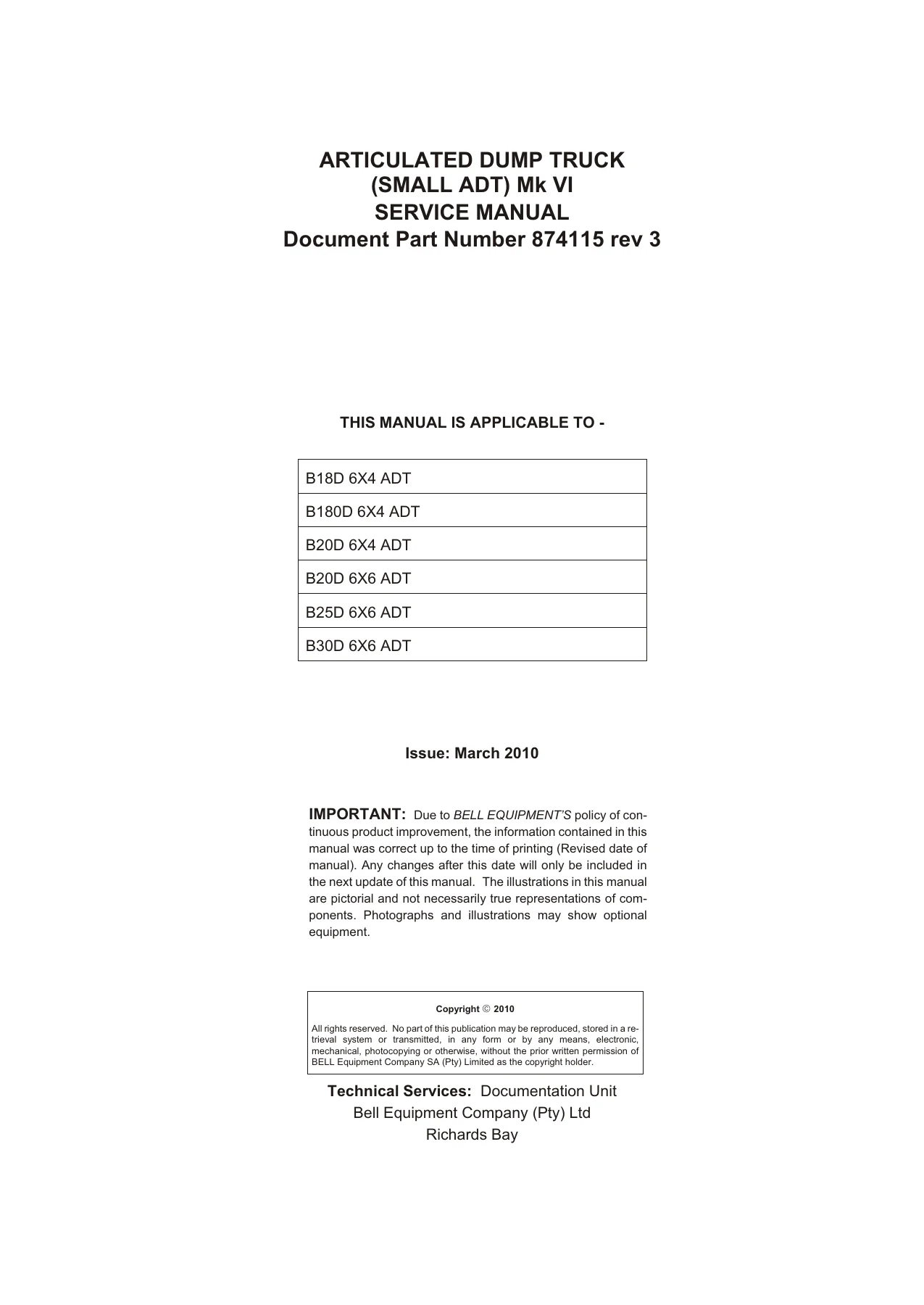
The Bell B18D-B30D Small ADT Mk VI Service Manual Rev 3 PDF is a 410-page technical service reference covering the B18D, B180D, B20D, B25D and B30D articulated dump truck configurations listed by Bell Equipment. It is written for experienced technicians and is structured around diagnosis, analysis, testing, adjustment and service work, with step-by-step procedures, system descriptions, schematics, specifications and troubleshooting information.

Coverage extends well beyond routine maintenance. The manual explains the OM 906 LA engine and its electronic unit injector fuel system, electrical and CANBUS systems, the ZF 6 HP 592 C PLUS transmission, pneumatic controls, steering and braking hydraulics, bin hydraulics, heating and air conditioning, service schedules and lubrication requirements. Dedicated diagnostic sections connect symptoms with probable causes, test procedures and corrective actions, making the Bell Small ADT Mk VI service manual useful when a fault has to be traced systematically rather than approached by trial and error.

Models Covered

This service manual specifically lists the following machines as applicable:

  • B18D 6X4 ADT
  • B180D 6X4 ADT
  • B20D 6X4 ADT
  • B20D 6X6 ADT
  • B25D 6X6 ADT
  • B30D 6X6 ADT

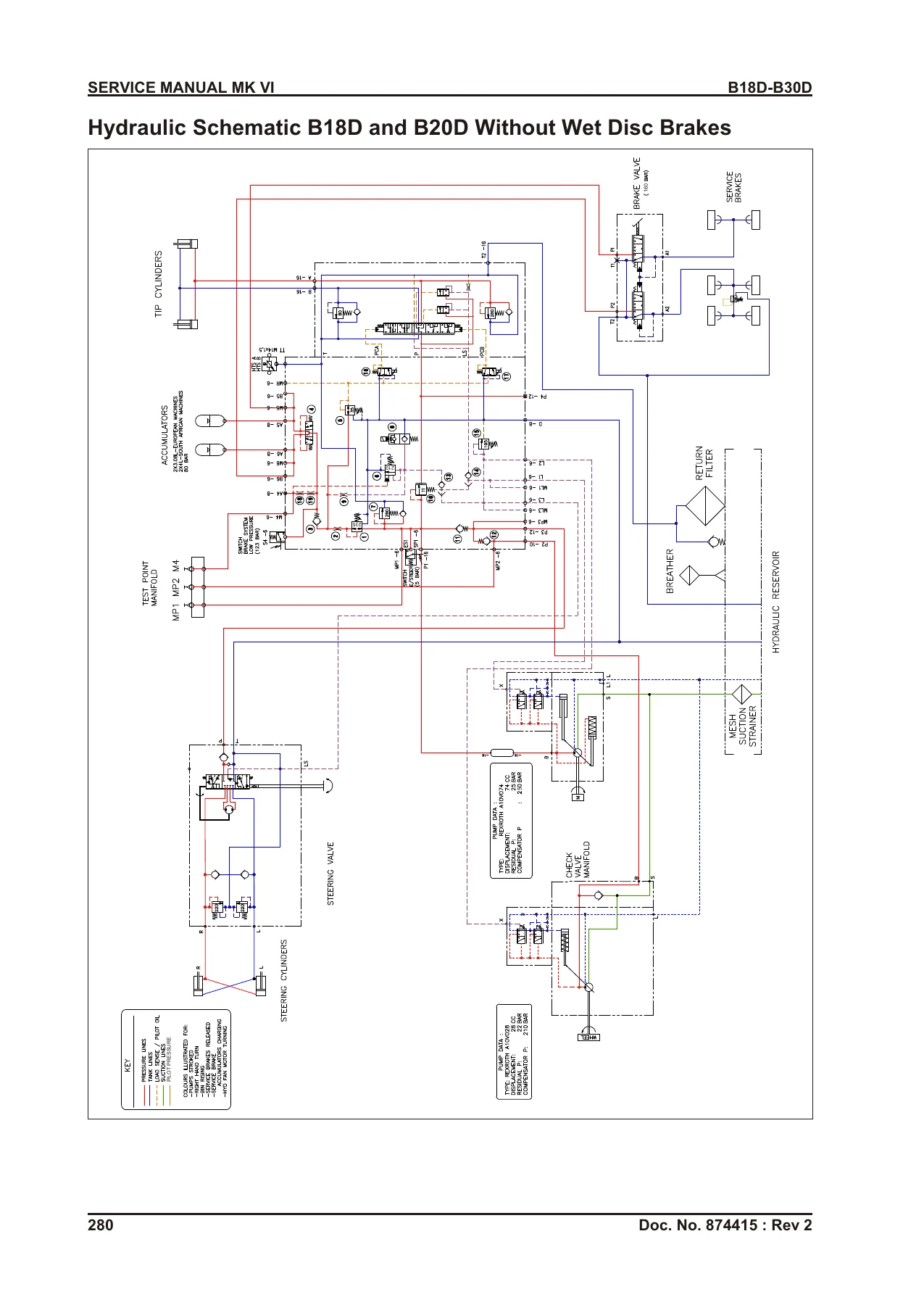
Because individual systems and configurations differ across the covered trucks, the manual identifies model-specific schematics and procedures where required. Examples include separate hydraulic schematics for B18D and B20D machines without wet disc brakes, B25D and B30D machines without wet disc brakes, and the B30D configuration with wet disc brakes.

Diagnosis, Testing and System Information

The engine chapter describes the six-cylinder, liquid-cooled OM 906 LA engine, including its electronic unit injector system, fuel delivery stages, cold-start operation and component arrangement. Diagnostic charts address conditions such as slow cranking, hard cold starting, failure to start, engine stopping after start, misfiring, low oil pressure, abnormal oil consumption and exhaust smoke. Test procedures include cylinder compression, fuel pump pressure, fuel intake pressure, low-pressure fuel circuit leakage and engine oil pressure. Valve-clearance and exhaust-brake adjustment procedures are also provided.

Electrical coverage is especially extensive. The manual contains starting and charging circuits, ignition and fuse circuits, monitor display circuits, controller inputs and outputs, air-conditioning wiring, Mercedes engine control wiring, ZF transmission wiring, diagnostic connections, connector data, earth points and fuse/relay layouts. The CANBUS J1939 section explains system communication between modules and provides procedures for diagnosing CAN shorts to earth, open circuits and shorts to positive voltage. Engine, CCU, MDU, OEU and transmission fault-code information is included alongside service-mode and menu information.

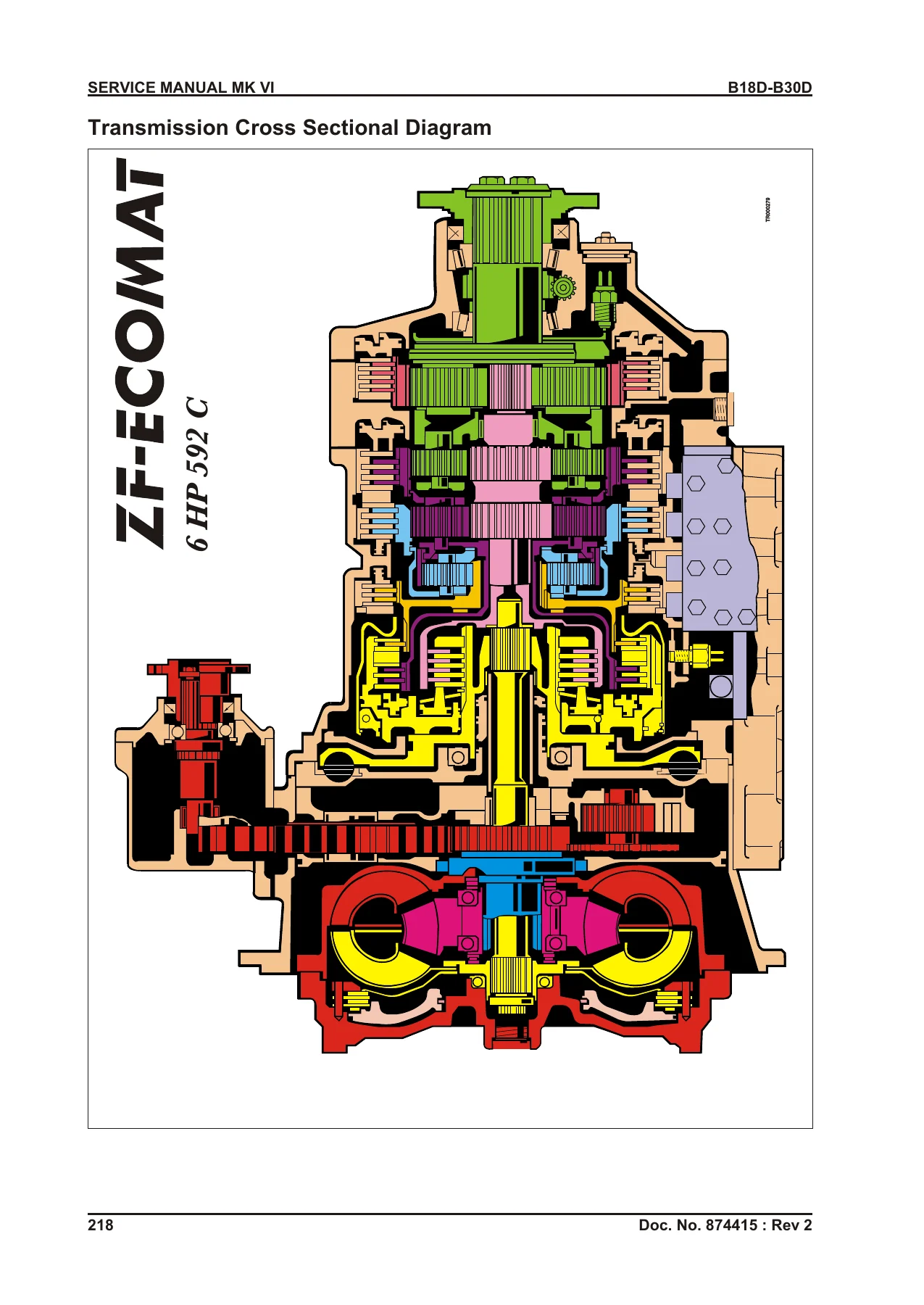
The transmission chapter focuses on the ZF 6 HP 592 C PLUS. It covers planetary gear operation and power flow, clutch configuration, a detailed transmission cross-sectional diagram, the hydraulic system, valve schematics, pressure information, retarder operation, gear-shift control, electrical circuitry, solenoids, sensors, valve-body work, wiring harnesses, diagnostic codes, power-train malfunction diagnosis, fluid-level checking and adjustment/test procedures.

Hydraulic information includes circuit symbols, complete model-specific schematics, main and secondary steering pump operation, steering valve operation, manifold views and schematics, service-brake operation, steering and secondary steering operation and bin operation. The diagnostic section is followed by pressure-setting and test procedures covering the main pump, emergency steering, steering circuit, brake circuits, accumulators, bin-tip pilot pressure and cycle-time testing. The manual also includes a hydraulic oil cleanup procedure using a portable filter caddy and a hydraulic warm-up procedure.

File Details

  • Manual type: Service Manual
  • Equipment: Articulated Dump Truck, Small ADT Mk VI
  • Brand: Bell Equipment
  • Models: B18D 6X4, B180D 6X4, B20D 6X4, B20D 6X6, B25D 6X6, B30D 6X6
  • Language: English
  • Pages: 410
  • File format: PDF
  • Document Part Number: 874115 rev 3
  • Issue: March 2010
  • Revision level: Revision 3

Chapters Covered

  • Safety
    • Specifications and general safety
    • Safety features
    • Material Safety Data Sheet information
    • ROPS and FOPS precautions
    • Noise emission levels and safety regulations
  • Tyre Information
    • Tyres and rims
    • Tyre pressures
    • Hot versus cold inflation pressure
  • Chapter 1. Operational Check-Out Procedure
    • Operational check
    • Ignition, engine-start and engine-stop checks
  • Chapter 2. Engine
    • Engine description and electronic unit injector fuel system
    • Diagnose engine malfunctions
    • Adjustments and tests
  • Chapter 3. Electrical System
    • Electrical schematics, earth connections and fuse/relay layout
    • Control-unit inputs and outputs
    • Engine, CCU, MDU and OEU fault codes
    • MDU3 menu structure and service mode
    • Specifications, tests and On Board Weighing troubleshooting
  • Chapter 4. Transmission ZF 6 HP 592 C PLUS
    • Planetary gears, power flows and clutch configuration
    • Transmission hydraulic system and pressure charts
    • Retarder and gear-shift control
    • Solenoids, sensors and valve body
    • Diagnostic codes, power-train diagnosis and adjustments
  • Chapter 5. Pneumatic System
    • Pneumatic system schematic and operation
    • Fault finding
    • Main pressure, park brake pressure and park brake adjustment
  • Chapter 6. Hydraulic System
    • Model-specific hydraulic schematics and system operation
    • Pumps, steering, manifold, service brakes and bin operation
    • Diagnostic procedure and hydraulic malfunction charts
    • Tests, pressure settings, accumulator checks and cycle-time test
  • Chapter 7. Heating, Ventilation and Air Conditioning
    • Air-conditioning cycle and heater-core operation
    • Fault finding and component locations
    • R134A system, switch, clutch, expansion-valve and refrigerant-leak tests
  • Chapter 8. Servicing, Schedules & Lubrication Chart
    • Hydraulic system overview and depressurising
    • Engine oil and recommended torque settings
    • Service schedules and lubrication chart
  • Chapter 9. 150 Hours Service and Checks
  • Chapter 10. 500 Hours Service and Checks
  • Chapter 11. 1 000 Hours Service and Checks
  • Chapter 12. 2 000 Hours Service and Checks
  • Chapter 13. 3 000 Hours Service and Checks
  • Chapter 14. 4 000 Hours Service and Checks
  • Chapter 15. As Required Service
  • Chapter 16. Miscellaneous Service and Checks
  • Chapter 17. Storage and Preservation
    • Storage up to 12 months
    • Storage from 12 to 36 months
    • Storage for more than 36 months
  • Chapter 18. Trouble Shooting

Taken together, these chapters provide a technician with a structured path from initial operational inspection through system theory, fault isolation, measurement and adjustment, followed by recurring service work. The maintenance schedule groups work at 150, 500, 1 000, 2 000, 3 000 and 4 000 running-hour intervals and also identifies tasks performed as required. Service subjects include engine oil and filtration, fuel filters, valve clearance, transmission and axle oils, hydraulic filters and oil, brake checks, electrical inspections, pneumatic components, lubrication points, cooling-system work and air-conditioning maintenance.

Service Data for Workshop Use

The Bell B18D-B30D Small ADT Mk VI Service Manual Rev 3 PDF contains numerous measured values and test specifications alongside the procedures that use them. Examples include engine idle-speed specifications, valve clearances, compression-test limits, fuel and oil pressure tests, transmission pressures, pneumatic-system tests, hydraulic pressure settings, accumulator checks, cycle-time testing and recommended torque-setting tables. This combination of procedure and specification is important when a technician needs to establish whether a system is actually within its prescribed operating range.

Illustrations and diagrams are used throughout the manual to identify components and explain system operation. These include engine and fuel-system diagrams, electrical circuit drawings, connector pin information, controller input/output layouts, the ZF transmission cross section, pneumatic circuitry, hydraulic schematics, manifold diagrams and HVAC component layouts. Troubleshooting information then ties many of these systems back to symptoms, probable causes and the tests needed to narrow the fault.

Get the Bell Small ADT Mk VI Service Manual Instantly

The Bell B18D-B30D Small ADT Mk VI Service Manual Rev 3 PDF gives technicians a detailed reference for diagnosing faults, checking system operation, carrying out adjustments, following scheduled service procedures and working from the correct specifications and circuit information for the covered B18D, B180D, B20D, B25D and B30D trucks. Using the documented test procedures, pressure values, diagrams, fault information and service intervals helps repairs and maintenance follow the methods set out for these machines instead of relying on guesswork.

Complete PDF Bookmark Tree

Complete Bookmarks

The complete bookmarks in the β€œBell B18D-B30D Small ADT Mk VI Service Manual Rev 3 PDF” are as follows:

TABLE OF CONTENTSp. 7
SAFETY 17p. 17
Specification 17p. 17
General 17p. 17
Safety Features 17p. 17
Material Safety Data Sheet (MSDS) 18p. 18
Unauthorised Modifications of ROPS and FOPS 18p. 18
Loosening or Removal Of ROPS and FOPS 18p. 18
Noise Emission Levels 18p. 18
Safety Regulations 19p. 19
General Safety 19p. 19
TYRE INFORMATION 30p. 30
Tyres and Rims 30p. 30
Tyre Pressures – General 30p. 30
Tyre Pressures – Inflation Pressure, Hot vs. Cold 30p. 30
CHAPTER 1. OPERATIONAL CHECK-OUT PROCEDURE 35p. 35
Operational Check 35p. 35
Ignition Button Pressed ONCE, Engine OFF 35p. 35
Ignition Button Pressed (Second Stage), Engine Start 36p. 36
Engine Stop Button Pressed 38p. 38
CHAPTER 2. ENGINE 39p. 39
Engine (OM 906 LA Shown) 39p. 39
Diagnose Engine Malfunctions 43p. 43
Adjustments 45p. 45
Display Menu Tachometer (B20D Shown) 45p. 45
Slow and Fast Idle Adjustment 45p. 45
Valve Clearance Adjustment 45p. 45
Exhaust Brake Adjustment 46p. 46
Tests 47p. 47
Cylinder Compression Test 47p. 47
Fuel Pump Pressure Test 48p. 48
Fuel Intake Pressure Upstream of Fuel Pump Test 50p. 50
Fuel System Low Pressure Fuel Circuit Leak Test 51p. 51
Oil Pump Pressure Test 52p. 52
CHAPTER 3. ELECTRICAL SYSTEM 55p. 55
Schematics 55p. 55
Electrical Schematic Symbols 55p. 55
Electrical Schematics 56p. 56
Earth Connections 79p. 79
Fuse and Relay Layout 79p. 79
SSM Inputs and Outputs 86p. 86
CCU2 J1 Inputs and Outputs 87p. 87
CCU2 J2 Inputs and Outputs 88p. 88
CCU2 J3 Inputs and Outputs 89p. 89
OEU J1 Inputs and Outputs 90p. 90
OEU J2 Inputs and Outputs 91p. 91
OEU J3 Inputs and Outputs 92p. 92
ADM-Mercedes ECU Inputs and Outputs 93p. 93
MR-Engine ECU Inputs and Outputs 94p. 94
ZF TCU Inputs & Outputs 95p. 95
Memory Module Inputs & Outputs 96p. 96
Connectors 97p. 97
Multiple Wire Colours 97p. 97
Wire Colour 97p. 97
Relay 97p. 97
Connectors 97p. 97
Engine Fault Codes (ADM) 129p. 129
Engine Fault Codes (PLD-MR) 133p. 133
CCU, MDU & OEU Fault Codes 149p. 149
MDU3 Menu Structure 164p. 164
Default Display 167p. 167
Accessing Service Mode 169p. 169
Main Menu 170p. 170
Specifications and Tests 198p. 198
On Board Weighing (OBW) Troubleshooting Guide 204p. 204
CHAPTER 4. TRANSMISSION ZF 6 HP 592 C PLUS 209p. 209
General Descriptions 209p. 209
Stall Speeds 213p. 213
Planetary Gears and Power Flows 214p. 214
The Basic Laws of Planetary Gear Sets 215p. 215
Ecomat Transmission Planetary Configuration 216p. 216
Transmission Clutch Configuration 217p. 217
Transmission Cross Sectional Diagram 218p. 218
Power Flow 219p. 219
Hydraulic System 220p. 220
Valve Schematic 1 221p. 221
Valve Schematic 2 222p. 222
Hydraulic Pressures 223p. 223
Pressure Chart 224p. 224
Retarder 225p. 225
Retarder Lever 226p. 226
ZF Gear Shift Control 227p. 227
Transmission Electrical Schematic 228p. 228
Internal Solenoids 229p. 229
Remove Valve Body 231p. 231
Solenoid Table 231p. 231
Renewing Sensors 232p. 232
External Solenoids 239p. 239
Diagnostic Codes 239p. 239
Wiring Harnesses 240p. 240
Diagnostic Information 241p. 241
Diagnostic Procedure 241p. 241
Diagnose Power Train System Malfunctions 242p. 242
Check the Transmission Fluid Level 247p. 247
Transmission Control Unit Error Codes 248p. 248
Table of Error Codes 249p. 249
Adjustments and Tests 263p. 263
CHAPTER 5. PNEUMATIC SYSTEM 267p. 267
Pneumatic System Schematic 267p. 267
Pneumatic System Operation 268p. 268
Fault Finding 272p. 272
Adjustments and Tests 274p. 274
Pneumatic System Main Pressure Test and Adjustment 274p. 274
Park Brake Pressure Test 274p. 274
Park Brake Adjustment 275p. 275
CHAPTER 6. HYDRAULIC SYSTEM 279p. 279
Hydraulic System Circuit Symbols 279p. 279
Hydraulic Schematic B18D and B20D Without Wet Disc Brakes 280p. 280
Hydraulic Schematic B25D and B30D Without Wet Disc Brakes 281p. 281
Hydraulic Schematic B30D With Wet Disc Brakes 282p. 282
Articulated Dump Truck Hydraulic System Operation 283p. 283
Main Hydraulic Pump Operation 285p. 285
Main Hydraulic Pump Load Sense Operation 286p. 286
Steering Valve Operation 288p. 288
Secondary Steering Pump Operation 290p. 290
Hydraulic System Manifold (Front View) 293p. 293
Hydraulic System Manifold (Rear View) 294p. 294
Hydraulic System Manifold (Right View) 295p. 295
Manifold Schematic 296p. 296
General Description 297p. 297
Service Brake System Operation 298p. 298
Steering And Secondary Steering System Operation 299p. 299
Bin Operation 300p. 300
Diagnostic Procedure 303p. 303
Diagnose Hydraulic System Malfunctions 304p. 304
Tests and Adjustments 312p. 312
Digital Thermometer Installation 312p. 312
Digital Analogue Pressure/Temperature Analyser Installation 312p. 312
Hydraulic Oil Cleanup Procedure Using Portable Filter Caddy 313p. 313
Hydraulic System Warm-Up Procedure 313p. 313
Setting Hydraulic Pressure 314p. 314
Activate the Hydraulic Pressure Setup Mode: 315p. 315
Calibrate the Bin Position Sensors: 315p. 315
Set the Emergency Steering Pump Pressures 315p. 315
Set the Emergency Steering Pump Residual Pressure 315p. 315
Set the Emergency Steering Pump Compensating Pressure: 316p. 316
Set the Main Pump Residual Pressures B18/B30 317p. 317
Set the Main Pump Compensating Pressure B18/B30 317p. 317
Set the Steering Pressure 319p. 319
Set the Brake Circuit Pressures: 319p. 319
Accumulator Charge Pressure Check and Re-charge Procedure 321p. 321
Set the Bin Tip Pilot Pressure 322p. 322
Cycle Time Test 323p. 323
CHAPTER 7. HEATING, VENTILATION AND AIR CONDITIONING 325p. 325
Air Conditioning System Cycle Of Operation 325p. 325
Heater Core Operation 326p. 326
Fault Finding 327p. 327
HVAC Component Location 329p. 329
Tests 331p. 331
Operational Checks 331p. 331
R134A Air Conditioning System Test 332p. 332
Air Freeze Control Switch Test 334p. 334
Air Compressor Clutch Test 334p. 334
Air High/Low Pressure Switch Test 334p. 334
Air Expansion Valve Test 335p. 335
Expansion Valve Bench Test 336p. 336
Refrigerant Leak Test 337p. 337
CHAPTER 8. SERVICING, SCHEDULES & LUBRICATION CHART 341p. 341
Hydraulic System Overview 341p. 341
De-pressurising the Hydraulic System 341p. 341
Engine Oil 342p. 342
Service Schedules 347p. 347
Lubrication Chart 352p. 352
CHAPTER 9. 150 HOURS SERVICE AND CHECKS 355p. 355
Service Instructions 355p. 355
CHAPTER 10. 500 HOURS SERVICE AND CHECKS 359p. 359
Service Instructions 359p. 359
Change Engine Oil And Replace Filter 359p. 359
Check Engine Air Intake System 359p. 359
Drain the Racor Fuel Filter 359p. 359
Check for oil leaks 360p. 360
Tilt and lower the cab 360p. 360
Loosen Cab Mounting Bolts Front And Rear Left Hand Side 360p. 360
Lower The Cab 361p. 361
The Transmission Fluid Level 361p. 361
Dipstick Check – Transmission Fluid COLD (Cold Check) 361p. 361
Dipstick Check – Transmission Fluid HOT (Hot Check) 362p. 362
Check Park Brake Pad Wear 363p. 363
Check Service Brake Pad Wear 363p. 363
Check The Transfer Case Fluid Level 364p. 364
Check Front Axle Suspension Struts 364p. 364
General Check Drive Line & Suspension Fasteners 365p. 365
Transfer Case Breather (Located under the Hydraulic Reservoir) 365p. 365
Transmission Breather And Axle Breathers 365p. 365
Middle Axle Breather 365p. 365
Rear Axle Breather 366p. 366
Inspect, Clean And Replace Cab Air Filter 366p. 366
Check Batteries, Clean And Tighten Terminals 367p. 367
Check Electrical Connectors, Harnesses And Looms 367p. 367
Check Work Lights, Reverse Buzzer And Horns 367p. 367
Record & Delete Fault Codes On The MDU 367p. 367
Check The Operator Controls And Instruments 368p. 368
Grease All Grease Points 368p. 368
Lubricate Bin Pivots 368p. 368
Articulation Joints, Oscillation Tube Through Drive Shaft Bearing Front And Steering Cylinders Rear Pivot Points 368p. 368
Oscillation Tube And Oscillation Tube Through Drive Shaft Bearing Rear 368p. 368
Grease Tailgate Pivot Points (If Equipped) 369p. 369
Check Hydraulic Oil Level 369p. 369
Service Brake Accumulator Routine Test 369p. 369
Replace Hydraulic Reservoir Breather 369p. 369
Grease Prop Shaft Slip Joint 370p. 370
Check Bin Shock Pad Clearance 370p. 370
Bin Pad Spacing (Field spacing only) 371p. 371
Clean Headlights 372p. 372
CHAPTER 11. 1 000 HOURS SERVICE AND CHECKS 373p. 373
Service Instructions 373p. 373
Adjust Engine Valve Clearance 373p. 373
Replace Primary Fuel Filter (Water Separator) 373p. 373
Replace Secondary Fuel Filter 373p. 373
Replace Crankcase Breather Filter 373p. 373
Remove Tappet Cover 373p. 373
Change the Primary Filter Element 374p. 374
Check Coolant Condition 375p. 375
Check The Fan Belt Condition 375p. 375
Replace Hydraulic Oil Return Filter 376p. 376
Check Axle Oil Level 377p. 377
Check Final Drive Oil Levels 377p. 377
CHAPTER 12. 2 000 HOURS SERVICE AND CHECKS 379p. 379
Service Instructions 379p. 379
Change the Secondary Filter Element 379p. 379
Change Transmission Oil 379p. 379
Drain Transmission Oil Cooler 379p. 379
Replace Transmission Oil Filters 380p. 380
Fill Transmission 380p. 380
Change Transfer Case Oil 380p. 380
Change Axle Oil 381p. 381
Change Final Drive Oil 382p. 382
Check Service Brake Disc Thickness 382p. 382
Check Front Hubs 382p. 382
Replace Pneumatic System Dryer Filter 383p. 383
CHAPTER 13. 3 000 HOURS SERVICE AND CHECKS 385p. 385
Service Instructions 385p. 385
Change jockey pulley bearing (Tensioner Pulley) 385p. 385
Remove Idler Pulley Assembly 385p. 385
Change Aircon Pulley Assembly 386p. 386
Change all axle driveline cross and rollers 386p. 386
Replace The Suction Screen 386p. 386
CHAPTER 14. 4 000 HOURS SERVICE AND CHECKS 387p. 387
Service Instructions 387p. 387
Replace Fan Belt 387p. 387
Change Hydraulic Oil 387p. 387
Fill Hydraulic Tank 388p. 388
Change Pneumatic Block Breather Filters 388p. 388
CHAPTER 15. AS REQUIRED SERVICE 389p. 389
Introduction 389p. 389
Service Instructions 389p. 389
Check the Engine Compartment Components 389p. 389
Clean/Replace Primer Pump Fuel Screen 390p. 390
Prime fuel system 390p. 390
Change Engine Coolant 391p. 391
Clean Cooling System 392p. 392
Check for Oil and Fuel Leaks 392p. 392
Clean the Air Cleaner Pre-cleaner Bowls 392p. 392
Clean Air Conditioning Filters 392p. 392
Grease Hinges 392p. 392
Check And Clean Coolers 392p. 392
Hydraulic Oil Cleanliness Sampling Procedure 392p. 392
CHAPTER 16. MISCELLANEOUS SERVICE AND CHECKS 395p. 395
Service Instructions 395p. 395
Inspect Serpentine Belt 395p. 395
Change Wheels 395p. 395
Using Battery Charger 395p. 395
Replace Batteries 396p. 396
Replace Front Turn Signal Bulb, Headlight Bulb and Front Park Light Bulb 396p. 396
Replace Front Turn Signal Bulb 397p. 397
Replace Headlight Bulb 397p. 397
Replace Front Park Light Bulb 397p. 397
Reassemble Headlight Assembly 397p. 397
Adjust Headlights 397p. 397
Replace Backup Light and Work Light (If Equipped) 398p. 398
Replace Tail and Brake Light and Rear Turn Signal Light 398p. 398
Replace Dome Light Bulb and Circuit Breaker Compartment Light Bulb 398p. 398
CHAPTER 17. STORAGE AND PRESERVATION 399p. 399
Introduction 399p. 399
General 399p. 399
Category 1 – Laid up for up to 12 months 399p. 399
Category 2 – Laid up for 12 to 36 months 400p. 400
Category 3- Laid up for up more than 36 months 400p. 400
CHAPTER 18. TROUBLE SHOOTING 401p. 401


IMAGES PREVIEW

Bell B18D-B30D Small ADT Mk VI Service Manual Rev 3 PDF β€” PDF page 1 preview
Bell B18D-B30D Small ADT Mk VI Service Manual Rev 3 PDF β€” PDF page 218 preview
Bell B18D-B30D Small ADT Mk VI Service Manual Rev 3 PDF β€” PDF page 280 preview

Your manual is supplied as an instant PDF download after purchase. There is no physical book and no shipping delay. The PDF can be opened on compatible phones, tablets and computers and can be printed when a paper reference is useful at the machine or in the workshop.

Reviews

There are no reviews yet.

Be the first to review “Bell B18D-B30D Small ADT Mk VI Service Manual Rev 3 PDF”

What Our Customers Say

β˜…β˜…β˜…β˜…β˜… Live reviews from customers
Loading customer reviews...
0
    0
    Your Cart
    Your cart is emptyReturn to Shop
    πŸ›’
    Recently Purchased
    πŸ•’ verified order