Description
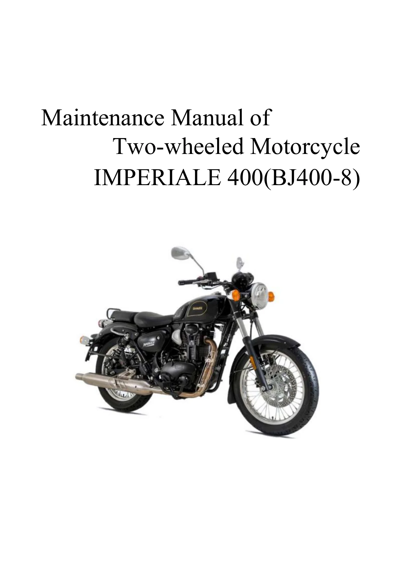
Benelli Imperiale 400 BJ400-8 Euro IV Service Manual
This comprehensive service manual provides detailed maintenance, repair, and overhaul instructions for the Benelli Imperiale 400 (model BJ400-8) electronic injection version. Whether you are performing routine maintenance, diagnosing an electronic fuel injection fault, or completely rebuilding the engine, this manual offers the technical specifications, exploded diagrams, and step-by-step procedures required to get the job done accurately.
File Details
- Manual Type: Service & Maintenance Manual
- Brand: Benelli
- Model: Imperiale 400 (BJ400-8)
- Version: Euro IV (European regulation) and Non-European
- Engine Code: BJ173FMQ-A
- Language: English
- Page Count: 497 pages
- File Format: PDF
- Document Coverage: Full vehicle – Engine, Chassis, Electrical, EFI, ABS
Chapters Covered
This manual is structured into comprehensive sections covering every major system of the motorcycle. The main chapters include:
- Preparatory Information: Safety rules, model identification, special tools, and cable/wire routing.
- Inspection and Maintenance: Regular maintenance checklist, engine oil/filter, throttle cable, air filter, spark plugs, battery, ignition timing, cylinder pressure, drive chain, brake systems, suspension, tires, and steering.
- Engine: Lubrication system, cylinder head cover, cylinder head, cylinder block and piston, crankcase, clutch, gearshift mechanism, drive system, electric starter mechanism, and exhaust emission control system.
- Electronic Fuel Injection (EFI): System introduction, technical parameters, ECU, fuel pump, throttle body, fuel injector, intake pressure and temperature sensor, oxygen sensor, engine cylinder head temperature sensor, canister solenoid valve, ignition coil, and fault diagnosis.
- Brake System: Front and rear brake discs, calipers, brake pads, master cylinders, brake fluid, brake hoses, and Anti-lock Brake System (ABS).
- Chassis and Body: Body cover, front wheel and suspension, rear wheel and suspension, fuel tank, seat, frame, sidestand, center stand, footpegs, and muffler.
- Electrical System: Battery/charging system, ignition system, starter motor, switches, lights, relays, fuses, and complete circuit diagram.
Beyond the chapter list, this Benelli Imperiale 400 BJ400-8 Euro IV service manual serves as a complete technical reference. It provides the exact torque values, clearances, and adjustment specifications needed for professional-grade repairs. The exploded diagrams and system schematics allow you to visualize the assembly order and understand how components interact, which is invaluable when tackling complex jobs like an engine rebuild or an ABS hydraulic system service. The EFI section is particularly detailed, offering step-by-step diagnostic procedures and fault code tables that are essential for troubleshooting modern electronic fuel injection issues without guesswork.
Why This Manual Matters for Your Benelli Imperiale 400
Working on a modern motorcycle like the Benelli Imperiale 400 requires more than just general mechanical knowledge. The Euro IV electronic fuel injection system, the ABS braking system, and the precise engine tolerances demand accurate specifications. Relying on generic advice or incomplete online forum posts can lead to incorrect adjustments, damaged components, or unsafe riding conditions. This manual provides the definitive factory-derived procedures and specifications. Whether you are adjusting the valve clearance, bleeding the ABS module, or replacing the drive chain, having the correct torque values and procedural steps at your fingertips ensures the job is done safely, efficiently, and correctly the first time.
Complete PDF Bookmark Tree
Complete Bookmarks
The complete bookmarks in the βBenelli Imperiale 400 BJ400-8 Euro IV Service Manual – Full Workshop & Repair Guideβ are as follows:
Introductionp. 6
+Preparatory Informationp. 6
General safetyp. 7
+Maintenance rulesp. 8
Installation of Batteryp. 8
Sharp edge of partp. 8
Solventp. 9
Cleaning the motorcycle before disassemblyp. 9
Sort out and clean the removed partsp. 9
Store the removed partsp. 10
Checkp. 10
Replacement partp. 10
Assembly sequencep. 11
Fastening sequencep. 11
Locking torquep. 11
Forcep. 12
Gasket, O-ringp. 12
Liquid gasket, locking agentp. 12
Press fittingp. 13
Ball bearing and needle bearingp. 13
Oil seal, grease sealp. 13
Circlip, cotter pinp. 14
Lubricationp. 14
Engine rotation directionp. 14
Wirep. 15
+Cable connector checkp. 15
1. Disconnectp. 15
2. Checkp. 15
3. Checkp. 16
4. Checkp. 16
5. Checkp. 16
Cable arrangementp. 17
+Model informationp. 18
Europep. 18
Non-Europeanp. 19
Motorcycle identificationp. 20
Important Notep. 20
Special toolsp. 21
Specification table (BJ400-8)p. 29
Unit conversion tablep. 31
+Winding method of cables, wires and hosesp. 32
Alignment of main cable:p. 32
Alignment of brake pipe:p. 44
Other matters:p. 56
+Troubleshooting Guidep. 69
+Diagnostic procedure for the fault that engine canp. 69
Starter motor does not work:p. 69
The starter motor is rotating, but the engine doesp. 69
The engine does not run:p. 69
Fuel does not flow:p. 69
No sparks; sparks are weak:p. 70
There is a problem with the fuel/air mixture:p. 70
Too low cylinder pressure:p. 70
+It cannot run properly at a low speed:p. 70
Sparks are weak:p. 70
There is a problem with the fuel/air mixture:p. 71
The cylinder pressure is low:p. 71
Others:p. 71
+It cannot run properly at a high speed or the powep. 71
Ignition is abnormal:p. 71
There is a problem with the fuel/air mixture:p. 71
The cylinder pressure is low:p. 72
There is a click sound:p. 72
Others:p. 72
+The temperature is too high:p. 72
Ignition is abnormal:p. 72
The muffler is overheated:p. 72
There is a problem with the fuel/air mixture:p. 73
The cylinder pressure is high:p. 73
The output force of engine is insufficient:p. 73
Not properly lubricated:p. 73
+The clutch is not working properly:p. 73
The clutch is slipping:p. 73
The clutch cannot be separated properly:p. 73
+There is a problem with shifting:p. 74
It is unable to operate the gear smoothly; controlp. 74
Jumpp. 74
Excessive speed change:p. 74
+The engine makes an unusual noise:p. 74
There is a click sound:p. 74
The piston makes a sound:p. 74
The valve makes noise:p. 75
+The drive system makes an unusual noise:p. 75
Clutch makes a noise:p. 75
The drive device makes a noise:p. 75
The drive system makes a noise:p. 75
+The frame makes an unusual noise:p. 76
The front fork makes a noise:p. 76
The rear shock absorber makes a noise:p. 76
The brake disc makes a noise:p. 76
Other noises:p. 76
+Excessive exhaust gas:p. 76
White exhaust:p. 76
Black exhaust:p. 76
Brown exhaust:p. 76
+Poor performance and / or stability:p. 76
It is difficult to rotate the handlebar:p. 76
The handlebars vibrate or shake severely:p. 77
The handlebar is placed on one side:p. 77
The damping effect is not ideal:p. 77
Brake is unable to work properlyp. 77
+Battery has failedp. 77
Battery has run out:p. 77
Battery is overcharged:p. 78
+Torque and locking agentp. 79
Locking torque and related parameters of nuts, bolp. 79
Main locking torque specificationsp. 80
+Inspection / adjustmentp. 84
Preparation standardp. 84
Regular maintenance checklistp. 87
Engine Oil/Filterp. 89
Inspection/adjustment of throttle cablep. 92
Air filterp. 93
Spark plugp. 95
Accumulatorp. 96
Ignition timingp. 99
Cylinder pressurep. 101
Drive chain slacknessp. 102
Free stroke of brakep. 102
Inspection of brake fluid for leakagep. 104
Inspection of brakep. 106
Inspection of brake fluid levelp. 106
Inspection of wear of brake padp. 107
Inspection of brake light switchp. 108
Headlightp. 109
Clutch cablep. 111
Front/rear suspension systemp. 111
Bolt/nut/fixturep. 112
Front / rear tirep. 113
Rim / tirep. 114
Steering Column Bearing and Handlebar Fixatorp. 114
Inspection and Maintenance of Electrical Systemp. 115
+I. Battery/Charging Systemp. 117
1.1 Preparatory Informationp. 117
+1.2 Fault Diagnosisp. 118
1.2.1 No powerp. 118
1.2.2 Discontinuous currentp. 118
1.2.3 Low voltagep. 118
1.2.4 Poor charging systemp. 119
+1.3 Batteryp. 119
1.3.1 Battery Disassemblyp. 119
1.3.2 Install batteryp. 120
1.3.3 Activation of batteryp. 120
1.3.4 First chargep. 122
1.3.5 Inspection of charging statep. 124
+1.4 Charging Systemp. 125
1.4.1 Inspection of Charging Statep. 125
+1.5 Disassembly of Voltage and Current Regulatorp. 126
1.5.1 Disassembly of voltage and current regulatorp. 126
1.5.2 Inspection of Circuit at Main Wiring Endp. 126
1.5.3 Inspection of Voltage and Current Regulatorp. 127
1.5.4 Installation of voltage and current regulatop. 127
+1.6 Alternatorp. 127
1.6.1 Disassemblyp. 127
1.6.2 Inspectionp. 128
1.6.3 Installationp. 129
+II. Ignition Systemp. 131
+2.1 Preparatory Informationp. 131
2.1.1 Precautions for operationp. 131
2.2 Fault Diagnosisp. 133
+2.3 Triggerp. 134
2.3.1 Disassembly of triggerp. 134
2.3.2 Inspectionp. 134
+2.4 Ignition Coilp. 134
2.4.1 Disassembly of ignition coil:p. 134
2.4.2 Inspection of Ignition Coilp. 136
+2.5 Spark Plugp. 136
2.5.1 Inspection of spark plugp. 136
2.6 ECUp. 137
+III. Starter Systemp. 139
3.1 Preparatory Informationp. 139
+3.2 Fault Diagnosisp. 140
3.2.1 Start failurep. 140
3.2.2 Too weak rotation force of starter motorp. 140
3.2.3 Starter motor can rotate but rotation enginep. 140
+3.3 Starter Motorp. 140
3.3.1 Disassemblyp. 140
3.3.2 Installationp. 141
+3.4 Starter Relayp. 141
3.4.1 Operation Inspectionp. 141
3.4.2 Inspection of Voltage of Starter Relayp. 141
3.4.3 Inspection of Bond Strap Circuit of Starterp. 142
3.4.4 Operation Inspectionp. 142
+IV. Bulbs /Switches/Metersp. 144
4.1 Preparatory Informationp. 145
+4.2 Fault Diagnosisp. 145
4.2.1 The βONβ light of main switch is off.p. 145
+4.3 Replacement of headlight bulbp. 146
4.3.1 Disassemblyp. 146
4.3.2 Installationp. 146
+4.4 Replacement of Turn Signal Light Bulbp. 147
4.4.1 Disassemblyp. 147
4.4.2 Installationp. 147
+4.5 Replacement of Taillight Bulbp. 148
4.5.1 Disassemblyp. 148
4.5.2 Installationp. 148
+4.6 Replacement of License Light Bulbp. 148
4.6.1 Disassemblyp. 148
4.6.2 Installationp. 149
+4.7 Metersp. 149
4.7.1 Disassemblyp. 149
4.7.2 Installationp. 150
+4.8 Ignition Switchp. 151
4.8.1 Disassemblyp. 151
+4.8.2 Replacement of Ignition Switchp. 152
4.8.2.1 Disassemblyp. 152
4.8.2.2 Installationp. 152
+4.9 Electric hornp. 152
4.9.1 Disassemblyp. 152
4.9.2 Installationp. 153
4.9.3 Inspectionp. 153
4.10 Handlebar Switchp. 154
+4.11 Inspection of switchp. 156
4.11.1 Connect the rear brake light switchp. 156
4.11.2 Connection of sidestand switchp. 156
+4.12 Speed sensorp. 157
4.12.1 Disassembly of speed sensorp. 157
4.12.2 Inspection of speed sensorp. 157
4.12.3 Installation of speed sensorp. 157
+4.13 Oxygen sensorp. 158
4.13.1 Disassembly of oxygen sensorp. 158
4.13.2 Inspection of oxygen sensorp. 158
4.13.3 Installation of oxygen sensorp. 158
+4.14 Fuel level sensorp. 159
4.14.1 Disassembly of fuel level sensorp. 159
4.14.2 Inspection of fuel level sensorp. 159
4.14.3 Installation of fuel level sensorp. 160
+4.15 Relay and fuse boxp. 161
4.15.1 Disassembly of relay and fuse boxp. 161
4.15.2 Inspection of relay circuitp. 162
4.15.3 Inspection of relay circuit (disconnect batp. 162
4.15.4 Inspection of relay circuit (with battery)p. 162
4.15.6 Internal circuit of relay boxp. 163
+4.16 Fusep. 165
4.16.1 Disassembly of fusep. 165
4.16.2 Installation of fusep. 166
4.16.3 Inspection of fusep. 167
Inspection and Maintenance of Chassisp. 168
+V. Brakep. 175
5.1 Preparatory Informationp. 175
+5.2 Fault Diagnosisp. 176
5.2.1 Poor brake performancep. 176
5.2.1 Slow reaction of brake or tight leverp. 176
5.2.1 Abnormal noise of brakep. 176
+5.3 Front Brake Discp. 177
5.3.1 Disassembly of front brake discp. 177
5.3.2 Installation of front brake discp. 178
5.3.3 Inspection of front brake discp. 179
+5.4 Rear Brake Discp. 179
5.3.1 Disassembly of rear brake discp. 179
5.3.2 Installation of rear brake discp. 180
5.3.3 Inspection of rear brake discp. 181
+5.5 Brake lever, brake pedalp. 182
5.5.1 Adjustment of position of brake leverp. 182
5.5.2 Inspection of position of brake pedalp. 182
5.5.3 Adjustment of position of brake pedalp. 182
5.5.4 Disassembly of brake pedalp. 183
5.5.5 Installation of brake pedalp. 183
+5.6 Caliperp. 185
5.6.1 Disassembly of front caliperp. 185
5.6.2 Disassembly of rear caliperp. 185
5.6.3 Installation of caliperp. 185
5.6.4 Disassembly of front caliperp. 186
5.6.5 Assembly of front caliperp. 187
5.6.7 Disassembly of rear caliperp. 189
5.6.8 Assembly of rear caliperp. 189
5.6.9 Inspection of fluid sea of caliper for damagp. 190
5.6.10 Inspection of dust seal of caliper for damap. 191
5.6.11 Inspection of the caliper piston and brakep. 192
+5.7 Brake padp. 192
5.7.1 Remove the front brake padp. 192
5.7.2 Installation of front brake padp. 193
5.7.3 Disassembly of Rear Brake Padp. 193
5.7.4 Installation of rear brake padp. 194
5.7.5 Inspection of wear of brake padp. 194
+5.8 Master cylinderp. 195
5.8.1 Disassemble front master cylinderp. 195
5.8.2 Installation of front master cylinderp. 196
5.8.3 Disassembly of rear master cylinderp. 197
5.8.4 Installation of rear master cylinderp. 197
5.8.5 Disassembly of front master cylinderp. 198
5.8.6 Disassembly of rear master cylinderp. 199
5.8.7 Assembly of master cylinderp. 199
5.8.8 Check the master cylinder (visual inspectionp. 200
+5.9 Brake fluidp. 200
5.9.1 Inspection of level of brake fluidp. 200
5.9.2 Replacement of brake fluidp. 200
5.9.3 Exhaust the air inside the brake linep. 202
+5.10 Brake hosep. 204
5.10.1 Disassembly / installation of brake hose anp. 204
5.10.2 Inspection of brake hoses and replacement op. 205
+5.11 Anti-lock brake system (ABS)p. 207
5.11.1 Part positionp. 207
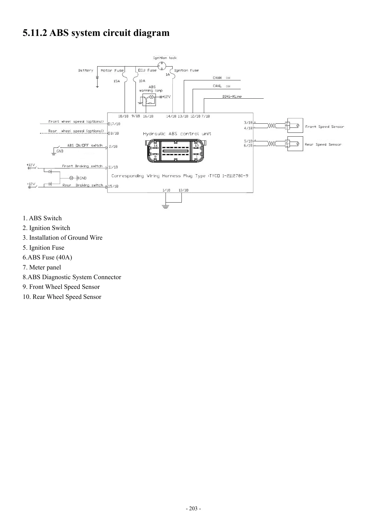
5.11.2 ABS system circuit diagramp. 208
5.11.3 Pin namep. 209
+5.11.4 ABS overhaulp. 210
5.11.4.1 Precautions for ABS overhaulp. 210
5.11.4.2 Overview of ABS fault removalp. 212
5.11.4.3 ABS diagnostic flow chartp. 214
5.11.4.4 Carry out the pre-diagnosis inspection (Pp. 216
5.11.4.5 Carry out the pre-diagnosis inspection (p. 217
5.11.4.6 Overview of diagnosisp. 217
5.11.4.7 Check the ABS indicator (LED)p. 218
5.11.4.8 ABS indicator (LED) is on (rotate the ignp. 218
5.11.4.9 ABS indicator (LED) is on (motorcycle isp. 219
5.11.4.10 The difference between front and rear whp. 220
5.11.4.11 Wheel speed sensor is open or shorted (fp. 220
5.11.4.12 Check the line of wheel speed sensor (fap. 220
5.11.4.13 Relay fault (C0044-C0046)p. 221
5.11.4.14 ABS normally open valve solenoid circuip. 221
5.11.4.15 ABS normally closed valve solenoid circup. 221
5.11.4.16 ABS voltage is too high, ABS voltage isp. 221
5.11.4.17 ABS pump or motor fault (C0070-C0074)p. 221
5.11.4.18 Intermittent signal of wheel speed sensop. 221
5.11.4.19 ABS wheel speed difference is too highp. 221
5.11.4.20 Brake diode breakdown (C0062)p. 221
5.11.4.21 Brake switch line fault (C0060-C0061)p. 222
5.11.4.22 ABS indicator light (LED) fault (C0210-Cp. 222
5.11.4.23 Speed output port fault (C0230-C0231)p. 222
5.11.4.24 Front wheel speed sensor signal is abnorp. 222
5.11.4.25 Rear wheel speed sensor signal is abnormp. 223
5.11.4.26 Check ECU (fault code: C0044-C0046)p. 224
+5.11.5 ABS hydraulic mechanismp. 225
5.11.5.1 Disassemble ABS hydraulic mechanismp. 225
5.11.5.2 Install ABS hydraulic mechanismp. 227
5.11.5.3 Check ABS hydraulic mechanismp. 228
+5.11.6 Speed sensorp. 229
5.11.6.1 Remove front wheel speed sensorp. 229
5.11.6.2 Install front wheel speed sensorp. 229
5.11.6.3 Remove rear wheel speed sensorp. 229
5.11.6.4 Install rear wheel speed sensorp. 230
5.11.6.5 Check front wheel speed sensorp. 230
5.11.6.6 Check the clearance of wheel speed sensorp. 231
5.11.6.7 Check the gear ring of wheel speed sensorp. 232
VI. Body Coverp. 242
+VII. Front Wheel/Front Suspensionp. 248
7.1 Preparatory Informationp. 249
+7.2 Fault Diagnosisp. 250
7.2.1Turning Difficulty of Handlebarp. 250
7.2.2Instability of Directionp. 250
7.2.3 Front Wheel Shimmyp. 250
7.2.4 Rotation Difficulty of Wheelp. 250
7.2.5 Abnormal Sound of Front Shock Absorberp. 250
+7.3 Front Wheelp. 250
7.3.1 Disassemblyp. 250
+7.3.2 Inspectionp. 252
7.3.2.1 Bending Inspection of Wheel Axlep. 252
7.3.2.2 Rim Shimmy Inspectionp. 252
7.3.2.3Inspection of Front Wheel Bearingp. 252
7.3.2.4 Inspection of spokep. 253
+7.3.3 Replacement of Bearingp. 253
7.3.3.1 Disassembly of Bearingp. 253
7.3.3.2 Inspection of Bearingp. 254
7.3.3.3 Installation of Bearingp. 254
7.3.4 Installationp. 254
+7.4 Handlebarp. 255
7.4.1 Disassemblyp. 255
7.4.2 Inspectionp. 258
7.4.3 Installationp. 258
+7.5 Front Forkp. 259
7.5.1 Disassemblyp. 259
7.5.2 Inspection of Steering Columnp. 262
7.5.3 Installationp. 263
+7.6 Front Shock Absorberp. 267
7.6.1 Disassemblyp. 267
7.6.2 Inspectionp. 268
7.6.3 Installationp. 269
+VIII. Rear wheel/rear suspensionp. 277
8.1 Preparation of Informationp. 277
+8.2 Fault Diagnosisp. 277
8.2.1 Rear Wheel Shimmyp. 277
8.2.2 Inflexible rotation of wheelp. 278
8.2.3 Poor brake performancep. 278
8.2.4 Inflexible Brake Pedal or Slow Returnp. 278
8.2.5 Abnormal sound of brakep. 278
+8.3 Rear wheelp. 278
8.3.1 Disassemblyp. 278
+8.3.2 Inspectionp. 280
8.3.2.1 Bending Inspection of Wheel Axlep. 280
8.3.2.2 Rear Rim Shimmy Inspectionp. 280
8.3.2.3 Inspection of Rear Wheel Bearingp. 281
8.3.2.4 Inspection of spokep. 281
+8.3.3 Replacement of Bearingp. 281
8.3.3.1 Disassembly of Bearingp. 281
8.3.3.2 Inspection of Bearingp. 282
8.3.3.3 Installation of Bearingp. 282
8.4.4 Installationp. 282
+8.4 Rear shock absorberp. 283
8.3.1 Disassemblyp. 283
8.3.2 Inspectionp. 284
8.3.4 Installationp. 284
+8.5 Rear Rocker Armp. 285
8.5.1 Disassemblyp. 285
8.5.2 Inspectionp. 286
8.5.3 Installationp. 287
+8.6 Chain drivep. 288
8.6.1 Disassemblyp. 288
8.6.2 Inspectionp. 291
+8.6.3 Replacement of bearingp. 293
8.6.3.1 Disassembly of bearingp. 293
8.6.3.2 Inspection of Bearingp. 293
8.6.3.3 Installation of Bearingp. 294
8.6.3 Installationp. 294
+IX. Fuel Tank/Seatp. 299
9.1 Preparatory Informationp. 299
9.2 Fault Diagnosisp. 299
+9.3 Seatp. 300
9.3.1 Disassemblyp. 300
9.3.2 Inspectionp. 301
9.3.3 Installationp. 301
+9.4 Fuel Tankp. 301
9.4.1 Disassemblyp. 301
9.4.2 Inspectionp. 303
9.4.3 Installationp. 305
+X. Framep. 311
10.1 Preparatory Informationp. 311
+10.2 Fault Diagnosisp. 312
10.2.1 Compression pressure is lowp. 312
10.2.2 The gear cannot be engagedp. 312
10.2.3 It's hard to shift gearsp. 312
10.2.4 Abnormal sound of crankcasep. 312
10.2.5 Engine is automatically stoppedp. 312
+10.3 Framep. 312
10.3.1 Disassembly of framep. 312
10.3.2 Installation of framep. 313
10.3.3 Inspection of framep. 313
+10.4 Sidestandp. 314
10.4.1 Disassembly of sidestandp. 314
10.4.2 Installation of sidestandp. 315
+10.5 Center standp. 315
10.5.1 Disassembly of center standp. 315
10.5.2 Installation of center standp. 316
+10.6 Pedalp. 316
+10.6.1 Front pedal assemblyp. 316
10.6.1.1 Disassembly of front pedal assemblyp. 316
10.6.1.2 Installation of front pedal assemblyp. 317
+10.6.2 Left rear footpegp. 318
10.6.2.1 Disassembly of left rear footpegp. 318
10.6.2.2 Installation of left rear footpegp. 318
+10.6.3 Rear right footpegp. 319
10.6.3.1 Disassembly of right rear footpegp. 319
10.6.3.2 Installation of rear right footpegp. 319
+10.7 Mufflerp. 320
10.7.1 Disassembly of mufflerp. 320
10.7.2 Installation of mufflerp. 321
+10.8 Disassembly/installation of enginep. 322
10.8.1 Exploded View of disassembly/installation op. 322
10.8.2 Disassembly of Enginep. 324
10.8.2 Installation of Enginep. 330
Inspection and maintenance of enginep. 336
+XI. Lubrication Systemp. 343
111.1 Preparatory Informationp. 343
+11.2 Troubleshootingp. 344
11.2.1 Oil level is too lowp. 344
11.2.2 Oil pressure is lowp. 344
11.2.3 There is no oil pressurep. 344
11.2.4 Oil pressure is highp. 345
11.2.5 Oil is pollutedp. 345
11.2.6 Oil is emulsifiedp. 345
+11.3 Fuel Pumpp. 345
11.3.1 Disassemblyp. 345
11.3.2 Inspection of Fuel Pumpp. 346
11.3.3 Assembly of Fuel Pumpp. 347
11.3.4 Installationp. 348
+XII. Cylinder Head Coverp. 351
12.1 Preparatory Informationp. 351
+12.2 Fault Diagnosisp. 351
12.2.1 Oil leakage or seepage of cylinder head covp. 351
+12.3 Cylinder head coverp. 352
12.3.1 Disassemblyp. 352
12.3.2 Inspectionp. 353
12.3.3 Installationp. 353
+XIII. Cylinder Headp. 360
13.1 Preparatory Informationp. 360
+13.2 Fault Diagnosisp. 361
13.2.1 Compression pressure is lowp. 361
13.2.2 The sound of cylinder head is abnormalp. 362
13.2.3 Compression pressure is too highp. 362
+13.3 Cylinder headp. 362
13.3.1 Disassemblyp. 362
13.3.2 Inspectionp. 365
13.3.3 Replacement of Valve Guidep. 368
13.3.4 Finishing Valve Seat Ringp. 370
13.3.5 Installationp. 371
+XIV. Cylinder Block and Pistonp. 377
14.1 Preparatory Informationp. 377
+14.2 Fault Diagnosisp. 380
14.2.1 Compression pressure is lowp. 380
14.2.2 Compression pressure is too highp. 380
14.2.3 Exhaust pipe is emitting white smokep. 380
14.2.4 The sound of piston is abnormalp. 380
+14.3 Cylinder Blockp. 380
14.3.1 Disassemblyp. 380
14.3.2 Inspectionp. 381
14.3.3 Installation of cylinderp. 381
+14.4 Pistonp. 382
14.4.1 Disassemblyp. 382
14.4.2 Inspectionp. 383
13.4.3 Installation of Pistonp. 385
+14.5 Crankshaft connecting rodp. 386
+XV. Crankcasep. 391
15.1 Preparatory Informationp. 391
15.2 Disassembly and Installation of Crankcase Beap. 392
+15.3 Crankcasep. 393
15.3.1 Disassembly of crankcasep. 393
15.3.2 Inspection of crankcasep. 393
15.4.3 Assembly of crankcasep. 395
+XVI. Clutchp. 400
16.1 Preparatory Informationp. 400
+16.2 Fault Diagnosisp. 401
16.2.1 Clutch lever is too hard to pullp. 401
16.2.2 Clutch is slipping when acceleratingp. 401
16.2.3 Clutch does not disengage or clutch disengap. 401
+16.3 Right Coverp. 402
16.3.1 Disassembly of Right Coverp. 402
16.3.2 Install the right coverp. 402
+16.4 Clutchp. 402
16.4.1 Disassembly of clutchp. 402
16.4.2 Inspectionp. 404
16.4.3 Installation of clutchp. 406
+XVII. Gearshift Mechanismp. 410
17.1 Preparatory Informationp. 410
+17.2 Fault Diagnosisp. 410
17.2.1 It is difficult to shift gearsp. 410
17.2.2 Shift pedal is not returnedp. 410
+17.3 Gearshift Mechanismp. 411
17.3.1 Disassemblyp. 411
17.3.2 Inspectionp. 412
17.3.3 Installationp. 414
+XVIII. Drive Systemp. 419
18.1 Preparatory Informationp. 419
+18.2 Fault Diagnosisp. 420
18.2.1 Drive system trips over stop or is out of gp. 420
18.2.2 The noise of engine is too largep. 420
+18.3 Drive systemp. 420
18.3.1 Primary shaft componentp. 420
18.3.2 Auxiliary shaft componentp. 421
18.3.3 Inspectionp. 421
+18.4 Installationp. 425
18.4.1 Assembly of Primary Shaft Component and Auxp. 425
18.4.2 Assembly of parts at the shift drump. 426
+18.4.3 Installation of drive systemp. 426
18.4.3.1 Installationp. 426
18.4.3.2 Inspectionp. 427
+XIX. Electric Starter Mechanismp. 430
19.1 Preparatory Informationp. 430
+19.2 Troubleshootingp. 430
19.2.1 Engine cannot startp. 430
+19.3 Electric starter mechanismp. 431
19.3.1 Disassembly of electric starter mechanismp. 431
19.3.2 Installation of electric starter mechanismp. 433
+XX. Exhaust Emission Control Systemp. 437
20.1 Guarantee of Exhaust Emission Control Systemp. 437
20.2 Regular Maintenance Noticep. 437
20.3 Mechanical Function of Exhaust Control Systemp. 438
+20.4 Catalyst Conversion Systemp. 439
20.4.1 Structure:p. 439
20.4.2 Description:p. 439
+XXI. Fuel injection system (EFI)p. 441
21.1 Introduction to EFIp. 441
21.2 EFI systemp. 442
21.3 EFI part positionp. 444
21.4 Technical parametersp. 445
+21.5 Precautions for EFI Overhaulp. 446
21.5.1 Precautions for EFI Overhaulp. 446
+21.6 ECUp. 447
21.6.1 Engine controller (MT05 ECU)p. 448
21.6.2 ECU Appearancep. 448
21.6.3 ECU disassemblyp. 448
21.6.4 ECU installationp. 449
21.6.5 Precautions for ECUp. 449
21.6.6 ECU power supply requirementsp. 449
21.6.7 ECU temperature requirementsp. 450
+21.7 Fuel Pumpp. 451
21.7.1 Working of fuel pumpp. 451
21.7.2Appearance of fuel pumpp. 451
21.7.3 Fuel pump compositionp. 452
21.7.4 Fuel pump label and logop. 452
21.7.5 Working environment of fuel pumpp. 453
+21.7.6 Maintenance process of fuel pump:p. 453
21.7.6.1 Safety protection:p. 453
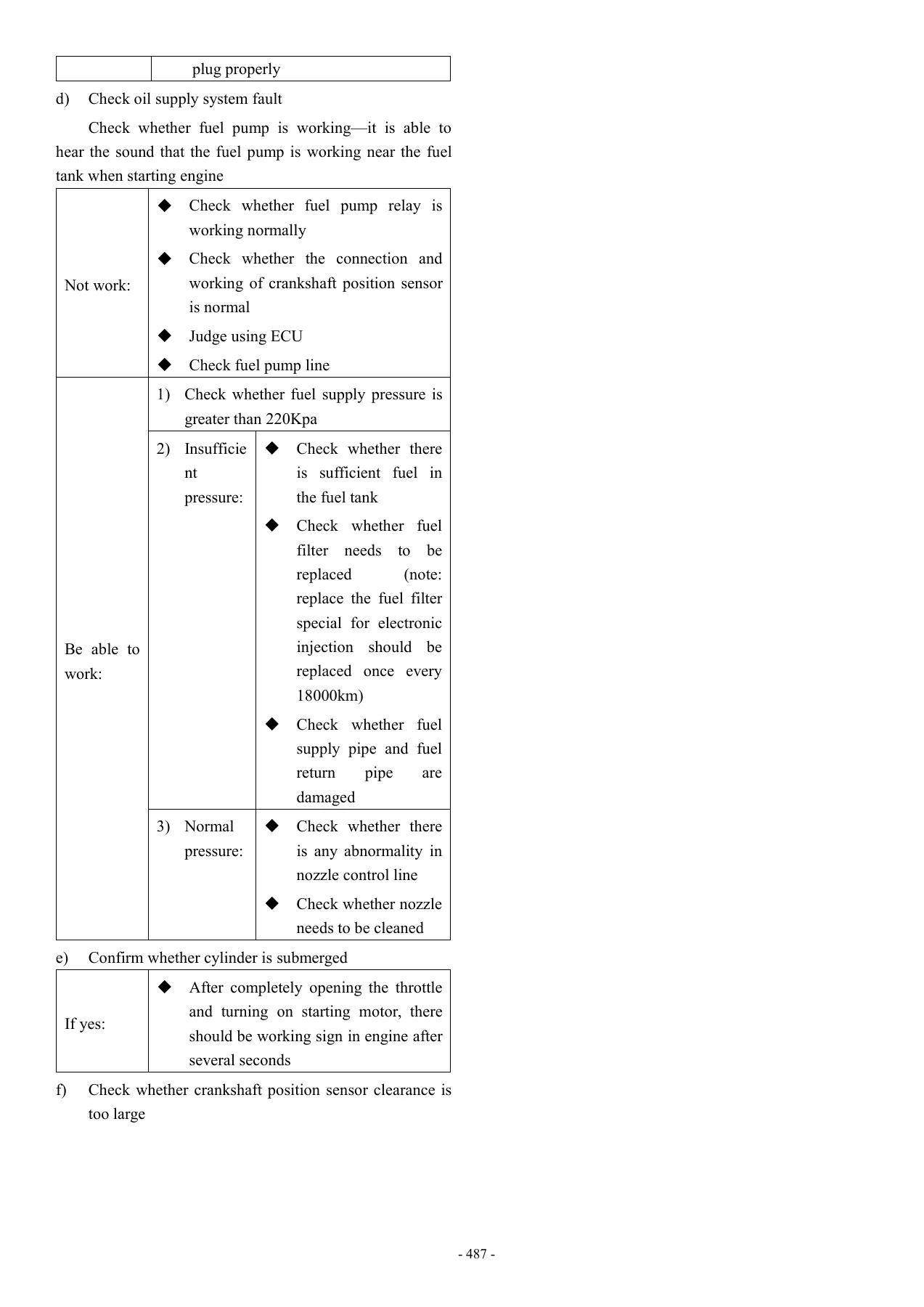
21.7.6.2 Fault diagnosis of fuel pump assemblyp. 454
21.7.6.3 Disassembly of fuel pump assembly:p. 454
21.7.6.4 Installation of fuel pump assembly:p. 454
21.7.6.5 Fuel pressure release process:p. 455
21.7.6.6 Fuel leakage check process:p. 455
21.7.7 Note for use:p. 455
21.7.8 common problemsp. 457
21.7.9 Fault maintenance and diagnosis methodp. 457
+21.8 Throttle Bodyp. 458
21.8.1 Working principle of throttle body:p. 458
21.8.2 Appearance of throttle body:p. 458
+21.8.3 Technical parametersp. 459
21.8.3.1 Throttle body:p. 459
21.8.3.2 Throttle position sensor:p. 459
21.8.3.3 Idle air control valve:p. 459
21.8.4 Operating temperature of throttlep. 459
21.8.5 Disassembly of throttle bodyp. 459
21.8.6 Cleaning method of throttlep. 459
21.8.7 Installation of throttle bodyp. 460
21.8.8 Note for the installation of throttle bodyp. 460
21.8.9 Note for the use of throttle bodyp. 460
+21.8.10 Idle speed stepper motorp. 461
21.8.10.1 Working principle of idle speed stepperp. 461
21.8.10.2 Appearance of idle speed stepper motorp. 461
21.8.10.3 Definition of pinp. 462
21.8.10.4 Characteristic parameters:p. 462
21.8.10.5 Fault determination of idle stepper motop. 462
21.8.10.6 Inspection of circuit of idle speed stepp. 463
21.8.10.7 Cleaningp. 463
21.8.10.8 Resetting of speed stepper motorp. 463
+21.9 Fuel injectorp. 464
21.9.1 Working principle of fuel injectorp. 464
21.9.2 Appearance of fuel injectorp. 464
+21.9.3 Fuel injector seal ringp. 464
21.9.3.1 O-ring seal connected to oil rail or oilp. 464
21.9.3.2 O-ring seal connected to intake pipe endp. 464
21.9.3.3 Recommended lubricantsp. 465
21.9.4 Overvoltage Impact of fuel injectorp. 465
21.9.5 Temperature range of fuel injector:p. 465
21.9.6 Fuel contaminants of fuel injectorp. 465
21.9.7 Fuel injector harness arrangementp. 465
21.9.8 Note for Use of Fuel Injectorp. 466
21.9.9 Installation requirements for fuel injectorp. 467
21.9.10 Replacement method of fuel injectorp. 467
21.9.11 Replaceability of fuel injectorp. 468
22.2.2.14 Blocking of fuel injectorp. 468
21.9.13 General failure mode and prevention and sop. 469
+21.10 Intake pressure and temperature sensorp. 470
21.10.1 Working principles of inlet pressure and tp. 470
21.10.2Appearance of inlet pressure sensorp. 470
21.10.3 Working environmentp. 470
21.10.4 Storage environmentp. 470
21.10.5 Electrical environmentp. 470
21.10.5 Pin definitionp. 471
21.10.6 Appearance of inlet pressure sensorp. 471
21.10.7 Cleaningp. 471
21.10.8 Fault determinationp. 471
+21.11 Oxygen sensorp. 472
21.11.1 Working principle of oxygen sensorp. 472
21.11.2 Appearance of oxygen sensorp. 472
21.11.2 Technical parametersp. 472
21.11.3 Installation requirementsp. 473
21.11.4 Oxygen sensor pin definition:p. 473
21.11.5 Fault determinationp. 473
21.11.6 Characteristic curvep. 474
21.11.7 Requirements for fuel qualityp. 474
+21.12 Temperature sensor of engine cylinder headp. 475
21.12.1 Working principle of temperature sensor ofp. 475
21.12.2 Appearance of temperature sensor of enginep. 475
21.12.3 Working environmentp. 475
21.12.4 Electrical environmentp. 476
21.12.5 Fault Determination and Characteristic ofp. 476
+21.13 Canister solenoid valve (ECP)p. 477
21.13.1 Overview of working principlep. 477
21.13.2 Appearancep. 477
21.13.3 Pin of ECP solenoid valvep. 477
21.13.4 Technical parametersp. 478
21.13.5 Installation requirementsp. 478
+21.14 Ignition coilp. 479
21.14.1Appearance of ignition coil:p. 479
21.14.2 Fault description:p. 479
+21.15 Fault maintenance and diagnosis method of EFp. 479
21.15.1 Diagnosis directly using the flashing faulp. 479
21.15.2 Diagnose fault using diagnostic apparatusp. 483
21.15.3 Inspection of fault using diagnostic softwp. 484
+21.16 Common troubleshooting methods for electronip. 489
21.16.1 Maintenance toolp. 489
+21.16.2Engine Working Data Flow Displayed by Diagnp. 489
21.16.2.1 Step Ip. 489
21.16.2.2 Step IIp. 490
21.16.2.3 Step IIIp. 490
+21.16.3 Simple troubleshootingp. 490
21.16.3.1 Daily use and maintenancep. 491
21.16.3.2 Fault phenomenon-Start faultp. 491
21.16.3.3 Fault phenomenonβStart failure with tempp. 493
21.16.3.4 Fault phenomenonβInstable idle speedp. 493
21.16.3.5 Fault phenomenonβToo high or too low idlp. 493
21.16.3.6 Fault phenomenonβInstable idle speed witp. 493
21.16.3.7 Fault phenomenonβInsufficient power of dp. 493
21.16.3.8 Fault phenomenonβSlight burning phenomenp. 494
21.16.3.9 Fault phenomenonβFault lamp is on, but fp. 494
21.16.3.10 Fault phenomenonβExtremely high fuel cop. 494
21.16.4 Fault diagnosis instructions for Delphip. 495
Circuit Diagram of BJ400-8 (electronic injection
η©Ίη½ι‘΅ι’p. 497
Instant PDF Download
This Benelli Imperiale 400 BJ400-8 Euro IV Service Manual is delivered as an instant PDF download. There is no waiting for shipping, no physical book to damage, and no subscription fees. Once your purchase is complete, you can immediately access the manual on your computer, tablet, or smartphone. The PDF format allows you to print only the pages you need for the garage, keeping your original digital copy clean and secure. Equip yourself with the knowledge to maintain, repair, and enjoy your Benelli Imperiale 400 for years to come.
Reviews
There are no reviews yet.