
★ TRUSTED BY 321,897+ PROFESSIONALS WORLDWIDE
🏢
Trusted Business
Verified & Licensed
🛡️
Virus Free Files
100% Safe Downloads
🔒
Secure Payment
SSL Protected
Instant Delivery
Available Immediately
Sale!

Bobcat 963 Skid-Steer Loader Service Manual – S/N 562215001 & Above / S/N 516515001 & Above

Original price was: $44.95.Current price is: $26.95.

640-page Bobcat 963 Service Manual covering loaders S/N 562215001 & Above and S/N 516515001 & Above. Includes hydraulic, hydrostatic, drive, electrical, engine, HVAC, maintenance, troubleshooting, schematics, repair procedures, and specifications for the 963 loader.

Instant PDF Download
Available immediately
💾
Save to Your Device
Download & keep forever
🛡️
Antivirus Scanned
100% virus-free
🌍
Trusted Worldwide
175,000+ customers

Description

Bobcat 963 Service and Repair Coverage

The Bobcat 963 Skid-Steer Loader Service Manual – S/N 562215001 & Above / S/N 516515001 & Above is a detailed mechanic’s reference for servicing, adjustment, troubleshooting, disassembly, inspection, repair, and reassembly of the Bobcat 963 loader and its major systems. The manual is organized as a shop-service document, moving from safety and routine service work through hydraulic, hydrostatic, drive, frame, electrical, engine, HVAC, and specification sections. It is especially useful when a repair requires more than a routine maintenance reference, because the procedures show component access, removal and installation sequences, test points, adjustment methods, inspection criteria, tightening information, and system-specific troubleshooting.

Coverage is tied to the serial-number groups printed on the manual: S/N 562215001 & Above and S/N 516515001 & Above. Serial-number identification matters because the manual itself notes that early or later machines may use different parts or require different procedures. The document also includes wiring and hydraulic/hydrostatic schematic material for the 963, plus service data for the Perkins/1004.40 t Turbo-Charged engine listed in the loader specifications.

File Details

  • Manual type: Service Manual
  • Brand / model: Bobcat 963 Loader
  • Serial-number coverage: S/N 562215001 & Above; S/N 516515001 & Above
  • Engine listed: Perkins/1004.40 t Turbo-Charged
  • Language: English
  • Page count: 640 pages
  • File format: PDF
  • Manual number: 6900988
  • Manual date: (3-06)
  • Revision: Revision No: 963-2, Date: 23 March 2006

What This Manual Helps You Service

The Bobcat 963 service manual goes well beyond basic fluid checks. Hydraulic work includes lift and tilt cylinders, control-valve service, the BICS valve, main relief-valve testing and adjustment, hydraulic pumps, filters, the reservoir, the lift-arm by-pass valve, bucket-position valve, and auxiliary-hydraulic components. Procedures are supported by photographs, component identification drawings, pressure checks, disassembly sequences, seal and O-ring replacement steps, and torque values where specified.

The hydrostatic section addresses steering, hydrostatic pumps and motors, charge and replenishing functions, oil cooling, drive-belt related service, pressure checks, neutral adjustments, and troubleshooting for symptoms such as loss of drive, tracking problems, overheating, and warning indications. The drive-system material covers the chaincase, brake, and related drive components. This allows the manual to support diagnosis across the complete power path rather than treating the engine, hydraulics, and final drive as isolated systems.

Electrical service is similarly broad. The manual contains electrical-system information, wiring schematics for applicable serial-number groups and options, diagnostic service codes, controller and BICS-related information, battery and starter service, lighting, sensors, control references, and electrical/hydraulic control identification. For technicians tracing an intermittent control or interlock fault, having the circuit references and component locations in the same service manual can reduce unnecessary disassembly.

Engine coverage includes removal and installation of the engine and mounts, air cleaner and cooling-fan service, engine controls, flywheel and housing work, exhaust and cooling components, engine-component testing, and a substantial engine-reconditioning section. The specifications identify a Perkins/1004.40 t Turbo-Charged diesel engine with four cylinders, while the engine specification pages provide dimensional and service data for internal components, fuel injection equipment, lubrication, cooling, and tightening requirements. HVAC coverage adds air-conditioning service procedures for the compressor, condenser, evaporator/heater unit, expansion valve, receiver/drier, heater components, charging and reclamation, temperature/pressure checks, and troubleshooting.

Chapters Covered

  • Safety & Maintenance
    • Bobcat Interlock Control System (BICS)
    • Fuel, engine lubrication and cooling-system service
    • Hydraulic/hydrostatic fluid and filter service
    • Lift arm support, lifting/blocking, towing and transporting
    • Operator cab, seat-bar restraint, Bob-Tach and Power Bob-Tach
    • Service schedule, tire maintenance and loader lubrication

    Complete PDF Bookmark Tree

    Complete Bookmarks

    The complete bookmarks in the “Bobcat 963 Skid-Steer Loader Service Manual – S/N 562215001 & Above / S/N 516515001 & Above” are as follows:

    MAINTENANCE SAFETY
    ALPHABETICAL INDEXp. 5
    CONTENTSp. 7
    FOREWORDp. 8
    SAFETY INSTRUCTIONS
    Fire Preventionp. 13
    SERIAL NUMBER LOCATIONSp. 15
    Loader Serial Numberp. 15
    Engine Serial Numberp. 15
    DELIVERY REPORTp. 15
    BOBCAT LOADER INDENTIFICATIONp. 16
    SAFETY & MAINTENANCE
    BOBCAT INTERLOCK CONTROL SYSTEM (BICS™)p. 19
    Inspecting The BICS™ Controller (Engine STOPPED – Key ON)p. 19
    Inspecting Deactivation Of The Auxiliary Hydraulics System (Engine STOPPED – Key ON)p. 19
    Inspecting The Seat Bar Sensor (Engine RUNNING)p. 19
    Inspecting The Traction Lock (Engine RUNNING)p. 19
    Inspecting The Lift Arm By-Pass Controlp. 19
    Additional Inspection For Loaders With Advanced Hand Controls (AHC)p. 20
    LIFTING AND BLOCKING THE LOADERp. 21
    Procedurep. 21
    TRANSPORTING THE LOADERp. 23
    Procedurep. 23
    TOWING THE LOADERp. 25
    Procedurep. 25
    LIFT ARM SUPPORT DEVICEp. 27
    Engaging The Lift Arm Support Devicep. 27
    Disengaging The Lift Arm support Devicep. 28
    HAND-LEVER BOB-TACHp. 29
    Inspection And Maintenancep. 29
    POWER BOB-TACH (OPTION)p. 31
    Inspection and Maintenancep. 31
    OPERATOR CABp. 33
    Descriptionp. 33
    Raising The Operator Cabp. 33
    Lowering The Operator Cabp. 34
    Emergency Exitp. 35
    SEAT BAR RESTRAINT SYSTEM (FOOT PEDALS)p. 37
    Descriptionp. 37
    Inspecting The Seat Barp. 37
    Maintaining The Seat Barp. 37
    SEAT BAR RESTRAINT SYSTEM (ADVANCED HAND CONTROLS)p. 39
    Descriptionp. 39
    Inspecting The Seat Barp. 39
    Maintaining The Seat Barp. 39
    REMOTE STARTp. 41
    Procedure for Loader Without, Attachments Control Harnessp. 41
    Procedure for Loader With Attachments Control Harnessp. 42
    Procedurep. 43
    SERVICE SCHEDULEp. 45
    FUEL SYSTEMp. 47
    Fuel Specificationsp. 47
    Filling the Fuel Tankp. 47
    Fuel Filtersp. 48
    Removing Air From The Fuel Systemp. 49
    AIR CLEANER SERVICEp. 51
    Replacing Filter Elementp. 51
    ENGINE LUBRICATION SYSTEMp. 53
    Checking Engine Oilp. 53
    Replacing OIl and Filterp. 54
    ENGINE COOLING SYSTEMp. 55
    Cleaning The Cooling Systemp. 55
    Checking The Coolant Levelp. 56
    Replacing The Coolantp. 56
    HYDRAULIC/HYDROSTATIC SYSTEMp. 59
    Checking And Adding Fluidp. 59
    Replacing The Hydraulic/Hydrostatic Filtersp. 59
    Replacing The Hydraulic Fluidp. 60
    Breather Capp. 61
    TIRE MAINTENANCEp. 63
    Wheel Nutsp. 63
    Tire Rotationp. 63
    Tire Mountingp. 63
    LUBRICATING THE BOBCAT LOADERp. 65
    Procedurep. 65
    HYDRAULIC SYSTEMp. 67
    HYDRAULIC/HYDROSTATIC SCHEMATICS
    HYDRAULIC SYSTEM INFORMATIONp. 73
    Glossary of Hydraulic/Hydrostatic Symbols for Loadersp. 73
    Troubleshooting Chartp. 77
    Tighten Proceduresp. 78
    CYLINDER(S)p. 79
    Checking The Lift Cylinder(s)p. 79
    Removal And Installation Of Lift Cylinder(s)p. 79
    Checking The Tilt Cylinder(s)p. 82
    Removal And Installation Of Tilt Cylinder(s)p. 83
    Tilt Cylinder Base End Pivot Pinp. 85
    Lift Cylinder Parts Identificationp. 87
    Tilt Cylinder Parts Identificationp. 88
    Disassemblyp. 89
    Assemblyp. 91
    MAIN RELIEF VALVEp. 95
    Checking Main Relief Valve At Front Auxiliary Hydraulicsp. 95
    Checking Main Relief Valve At Control Valve.p. 97
    Removal And Installationp. 99
    Adjustmentp. 100
    MAIN RELIEF VALVE (ADVANCED HAND CONTROL) (AHC)p. 103
    NOT AVAILABLE AT TIME OF PRINTINGp. 103
    HYDRAULIC CONTROL VALVE (FOOT CONTROL)p. 105
    Removal And Installationp. 105
    BICS™ Valve, Removal And Installationp. 110
    BICS™ Valve, Lift Arm By-Pass Orifice Disassembly And Assemblyp. 111
    BICS™ Valve, Check Valve Disassembly And Assemblyp. 112
    BICS™ Valve, Lock Valve Disassembly And Assemblyp. 113
    BICS™ Valve, Solenoid Disassembly And Assemblyp. 114
    BICS™ Valve, Solenoid Testingp. 115
    Identification Chartp. 115
    Load Check Valvep. 116
    Main Relief Valvep. 117
    Port Relief Valve, Tilt Spool (Linkage End)p. 118
    Port Relief Valve, Lift Spool (Bonnet End)p. 118
    Anti-Cavitation Valve/Port Relief Valve, Tilt Spool (Bonnet End)p. 119
    Anti-Cavitation Valve, Lift Spool (Linkage End)p. 119
    Rubber Bootp. 120
    Lift And Tilt Lock Blockp. 120
    Lift Spool and Detentp. 121
    Tilt Spool Removal And Installationp. 130
    Auxiliary Spool Removal And Installation (Bonnet End)p. 132
    Auxiliary Spool Removal And Installation (Linkage End)p. 133
    Auxiliary Plug Removal And Installationp. 134
    Auxiliary Electric Solenoid Disassemblyp. 134
    Port Relief-Auxiliary Section Disassemblyp. 135
    Cleaning And Inspectionp. 136
    HYDRAULIC CONTROL VALVE (ADVANCE HAND CONTROL) (AHC)p. 137
    NOT AVAILABLE AT TIME OF PRINTINGp. 137
    LIFT ARM BY-PASS CONTROL VALVEp. 139
    Removal And Installationp. 139
    Disassembly And Assemblyp. 140
    HYDRAULIC PUMPp. 141
    Checking the Output of the Pumpp. 141
    Removal And Installationp. 142
    Disassembly and Assemblyp. 144
    HYDRAULIC PUMPp. 151
    Disassembly And Assemblyp. 151
    Inspectionp. 154
    HYDRAULIC/HYDROSTATIC FILTERp. 155
    Removal And Installationp. 155
    COOLING FAN FILTERp. 157
    Removal And Installationp. 157
    HYDRAULIC FLUID RESERVOIRp. 159
    Removal And Installationp. 159
    CONTROLSp. 165
    Control Pedal Removal And Installationp. 165
    Control Pedal Adjustmentp. 165
    Control Pedals Mounting Panel Removal And Installationp. 165
    BUCKET POSITION VALVEp. 169
    Removal And Installationp. 169
    Disassembly And Assemblyp. 170
    TILT JUNCTION BLOCKp. 173
    Removal And Installationp. 173
    REAR AUXILIARY DIVERTERp. 175
    Removal And Installationp. 175
    Disassemblyp. 178
    Inspectionp. 179
    Solenoid Testingp. 179
    Assemblyp. 179
    HYDROSTATIC SYSTEMp. 181
    HYDROSTATIC SYSTEM INFORMATIONp. 183
    Troubleshooting Chartp. 183
    Replenishing Valve Functionp. 184
    CONTROL PANELp. 185
    Removal And Installationp. 185
    STEERINGp. 189
    Lever Removal And Installationp. 189
    Disassembly And Assemblyp. 189
    Neutral Adjustmentp. 200
    HYDROSTATIC MOTORp. 203
    Removal and Installationp. 203
    Throttle Controlp. 205
    Shuttle Check Valvep. 205
    Flushing Valvep. 206
    Disassemblyp. 207
    Inspectionp. 210
    Assemblyp. 212
    Cover Removal And Installationp. 217
    Neutral Adjustmentp. 217
    CHARGE PRESSUREp. 219
    Checking The Charge Pressurep. 219
    HYDROSTATIC PUMPp. 221
    Removal And Installationp. 221
    Replenishing/High Pressure Relief Valvep. 222
    Charge Relief Valvep. 223
    DA Controllerp. 223
    Disassemblyp. 224
    Inspectionp. 232
    Assemblyp. 234
    Hydrostatic Pump Start-Upp. 244
    Neutral Adjustmentp. 245
    Timing Procedurep. 247
    DRIVE BELTp. 253
    Shield Removal And Installationp. 253
    Replacementp. 254
    Adjustmentp. 254
    Tensioner Pulley Removal And Installationp. 255
    Tensioner Tension Springp. 256
    Tensioner Pulley Disassembly And Assemblyp. 256
    Tensioner Pivot Shaftp. 257
    Idler Pulley Removal And Installationp. 258
    OIL COOLERp. 259
    Removal And Installationp. 259
    DRIVE SYSTEMp. 261
    BRAKEp. 263
    Pedal Removal And Installationp. 263
    Pedal Disassembly And Assemblyp. 264
    Two Speed Block Removal And Installationp. 265
    Two Speed Block Disassembly And Assemblyp. 266
    Parking Brake Removal And Installationp. 271
    Parking Brake Disassembly And Assemblyp. 272
    DRIVE COMPONENTSp. 277
    Axle Seal Removal And Installationp. 277
    Axle, Bearings And Sprocket Removal And Installationp. 280
    Drive Chains Removal And Installationp. 285
    CHAINCASEp. 287
    Checking And Adding Oilp. 287
    Front Chaincase Cover Removal And Installationp. 287
    Rear Chaincase Cover Removal and Installationp. 287
    Reduction Gearcase Removal And Installationp. 288
    Reduction Gearcase Disassembly And Assemblyp. 292
    Removing The Oil From The Chaincasep. 300
    MAIN FRAMEp. 301
    SEAT BARp. 303
    Removal And Installationp. 303
    Assembling Componentsp. 304
    Compression Spring Disassembly And Assemblyp. 306
    OPERATOR CABp. 307
    Gas Cylinder Removal And Installationp. 307
    Gas Cylinder Bracket Disassembly And Assemblyp. 308
    Removal And Installationp. 309
    OPERATOR SEATp. 313
    Removal And Installationp. 313
    Slide Rail Removal And Installationp. 313
    Cushion Removal And Installationp. 314
    Back Removal And Installationp. 315
    Shock Removal And Installationp. 315
    BOB-TACHp. 317
    Removal And Installationp. 317
    Bob-Tach Lever And Wedgep. 319
    Bob-Tach Stopsp. 320
    POWER BOB-TACHp. 321
    NOT AVAILABLE AT TIME OF PRINTINGp. 321
    LIFT ARMSp. 323
    Removal And Installationp. 323
    REAR GRILLp. 327
    Gas Cylinder Removal And Installationp. 327
    REAR DOORp. 329
    Removal And Installationp. 329
    Adjusting The Rear Door Latchp. 330
    Door Latch Removal And Installationp. 331
    Door Brace Removal And Installationp. 331
    FUEL TANKp. 333
    Front Removal And Installationp. 333
    Fuel Level Senderp. 334
    Rear Removal And Installationp. 335
    Pick-up Tube Screenp. 337
    ELECTRICAL SYSTEM & ANALYSISp. 339
    ELECTRICAL SCHEMATICS
    ELECTRICAL SYSTEM INFORMATIONp. 353
    Troubleshooting Chartp. 355
    Descriptionp. 356
    Fuse Locationp. 358
    Relay Switch Locationp. 358
    Solenoid Testp. 359
    BATTERYp. 361
    Removal And Installationp. 361
    Servicing The Electrical Systemp. 363
    Using A Booster Battery (Jump Starting)p. 364
    ALTERNATORp. 365
    Alternator Output Testp. 365
    Rectifier (Diode) Testp. 365
    Alternator Regulator Testp. 366
    Removal And Installationp. 367
    Adjusting The Alternator Beltp. 369
    Disassemblyp. 370
    Stator Continuity Testp. 370
    Stator Ground Testp. 370
    Rotor Continuity Testp. 371
    Rotor Ground Testp. 371
    Rectifier Continuity (Diode) Testp. 371
    Assemblyp. 372
    STARTERp. 375
    Removal And Installationp. 375
    Parts Identificationp. 377
    Disassembly And Assemblyp. 378
    External Pinionp. 380
    Inspection And Repairp. 381
    Magnetic Switch Testp. 384
    No Load Testp. 385
    INSTRUMENT PANELp. 387
    Left Panelp. 387
    Right Panel – Standard Instrument Panel (With Key Switch)p. 388
    Right Panel – (Deluxe) (With Keyless Start)p. 389
    Right Panel Set Up Display Options (Deluxe)p. 391
    Passwordsp. 392
    Option And Field Accessory Panelsp. 394
    Standard Panel Removal And Installation (Right Side)p. 395
    Standard Panel Removal And Installation (Right Side) (Cont'd)p. 396
    Deluxe Panel Removal And Installation (Right Side)p. 396
    Standard And Deluxe Panel Removal And Installation (Left Side)p. 397
    LIGHTSp. 399
    Front Removal And Installationp. 399
    Rear Removal And Installationp. 400
    BOBCAT CONTROLLERp. 401
    Identification Chartp. 401
    Removal And Installationp. 402
    DIAGNOSTICS SERVICE CODESp. 405
    Displayp. 405
    BICS™ SYSTEMp. 407
    Inspecting The BICS™ Controller (Engine STOPPED – Key ON)p. 407
    Inspecting Deactivation Of The Auxiliary Hydraulics System (Engine STOPPED – Key ON)p. 407
    Inspecting The Seat Bar Sensor (Engine RUNNING)p. 407
    Inspecting The Traction Lock (Engine RUNNING)p. 407
    Inspecting The Lift Arm By-Pass Controlp. 407
    Additional Inspection For Loaders With Advanced Hand Controls (AHC)p. 408
    Troubleshooting Chartp. 409
    Troubleshooting Guidep. 410
    SEAT BAR SENSORp. 411
    Troubleshooting Chartp. 411
    Testp. 412
    Removal And Installationp. 413
    BICS™ Circuit Testp. 414
    TRACTION LOCKp. 417
    Troubleshooting Chartp. 417
    ADVANCED HAND CONTROL (A.H.C.) SYSTEMp. 419
    Components Identificationp. 419
    Troubleshooting Guidep. 420
    Parts Identificationp. 421
    A.H.C. Controller Removal And Installationp. 422
    Handle Control Unit Connectorp. 423
    Switch Handle Removal and Installationp. 424
    Actuators Disassembly and Assemblyp. 427
    PROPORTIONAL CONTROL (PWM)p. 429
    Troubleshooting Chartp. 429
    Control Handle Testingp. 430
    Electric Solenoid Coil Testingp. 430
    ELECTRICAL/HYDRAULIC CONTROLS REFERENCEp. 431
    Controls Identification Chartp. 431
    ENGINE SERVICEp. 433
    TROUBLESHOOTINGp. 437
    Chartp. 437
    ENGINE SPEED CONTROLp. 439
    Removal And Installationp. 439
    Disassembly And Assemblyp. 439
    MUFFLERp. 441
    Spark Arrestor Cleaning Procedurep. 441
    Removal And Installationp. 442
    Exhaust Extension Pipe.p. 443
    AIR CLEANERp. 445
    Housing Removal And Installationp. 445
    RADIATORp. 447
    Coolant Recovery Tank Removal And Installationp. 447
    Removal And Installationp. 447
    COOLING FANp. 451
    Removal And Installationp. 451
    Disassembly And Assemblyp. 453
    Blower Housing Removal And Installation (Cont'd)p. 457
    ENGINE COMPONENTS AND TESTINGp. 459
    Fuel Injection Pump Removal And Installationp. 459
    Fuel Injector Removal and Installationp. 461
    Fuel Injector Checkingp. 464
    Checking The Fuel Lift Pumpp. 464
    Removal And Installationp. 465
    ENGINE AND ENGINE MOUNTSp. 467
    Removal And Installationp. 467
    Mounting Brackets Removal And Installationp. 472
    FLYWHEEL AND HOUSINGp. 473
    Flywheel Removal And Installationp. 473
    Ring Gear Removalp. 474
    Ring Gear Installationp. 474
    RECONDITIONING THE ENGINEp. 475
    Intake Manifold Removal and Installationp. 475
    Exhaust Manifold Removal and Installationp. 476
    Cylinder Head Disassemblyp. 476
    Cylinder Head Removalp. 478
    Cylinder Head Inspectionp. 479
    Cylinder Head Installationp. 479
    Rocker Shaft Disassembly And Assemblyp. 482
    Valve Removalp. 483
    Valve Springs Checkingp. 483
    Valve Depth Checkingp. 484
    Valve Guides Checkingp. 484
    Valve Guide Removalp. 485
    Valve Guide Installationp. 485
    Valves Checkingp. 486
    Cutting A Valve Seatp. 486
    Valve Seat Assemblyp. 486
    Changing Valve Springs (With Cylinder Head Installed)p. 487
    Valve Clearance Adjustmentp. 488
    Timing Case And Drive Assembly Descriptionp. 489
    Timing Cover Removalp. 489
    Timing Cover Installationp. 489
    Front Oil Seal Removalp. 490
    Front Oil Seal Installationp. 490
    Timing Case And Gear Removalp. 491
    Timing Case And Gear Installationp. 492
    Camshaft And Tappets Removalp. 493
    Camshaft And Tappets Installationp. 493
    Pistons And Connecting Rods Descriptionp. 495
    Pistons And Connecting Rods Removalp. 495
    Pistons And Connecting Rods Disassemblyp. 496
    Piston Ring End Gapp. 497
    Piston Ring Installationp. 497
    Piston Ring Groove Clearancep. 498
    Connecting Rod Inspectionp. 498
    Connecting Rod Bushing Replacementp. 498
    Piston And Connecting Rod Assemblyp. 498
    Piston And Connecting Rod Installationp. 499
    Checking Piston Heightp. 500
    Crankshaft And Bearings Descriptionp. 500
    Crankshaft And Bearings Removalp. 500
    Inspection Of Crankshaft And Bearingsp. 502
    Crankshaft And Bearings Installationp. 503
    Rear Oil Seal Removalp. 504
    Rear Oil Seal Housing Positioningp. 504
    Rear Oil Seal Installationp. 505
    Checking Crankshaft End Playp. 505
    Cooling System Descriptionp. 506
    Thermostat Removal and Installationp. 507
    Thermostat Testingp. 508
    Water Pump Removalp. 508
    Water Pump Installationp. 509
    Engine Oil Cooler Removal And Installationp. 509
    Engine Oil Cooler Disassembly And Assemblyp. 511
    Engine Lubrication System Descriptionp. 512
    Oil Filter Adapter Removalp. 513
    Oil Filter Adapter Installationp. 513
    Oil Pan Removal And Installationp. 514
    Oil Screen And Pick-up Tubep. 514
    Oil Pump Removalp. 514
    Oil Pump Installationp. 515
    Oil Pump Disassembly And Assemblyp. 516
    Oil Pressure Relief Valve Disassembly And Assemblyp. 517
    Engine Block Descriptionp. 517
    Engine Block Disassembly And Assemblyp. 518
    Piston Cooling Jet Removalp. 518
    Piston Cooling Jet Installationp. 518
    Piston Cooling Jet Alignmentp. 519
    Inspectionp. 519
    Cylinder Liner Inspectionp. 519
    Cylinder Liner Removalp. 520
    Cylinder Liner Installationp. 521
    Turbo Charger Troubleshootingp. 522
    Turbo Charger Descriptionp. 523
    Turbo Charger Removal and Installationp. 523
    HEATING, VENTILATION, AIR CONDITIONINGp. 525
    AIR CONDITIONING SYSTEM FLOWp. 528
    Principalsp. 528
    Chartp. 529
    COMPONENTSp. 531
    Identificationp. 531
    SAFETYp. 535
    Safety Equipmentp. 535
    REGULAR MAINTENANCEp. 537
    Filter Elements Removal And Installationp. 537
    Compressor Drive Belt Inspectionp. 538
    Cleaning The Condenserp. 539
    BASIC TROUBLESHOOTINGp. 541
    Poor A/C Performancep. 541
    Cleaning The A/C Evaporator Coil & Heater Coilp. 541
    Compressor Drive Belt Inspection:p. 544
    Checking The Electrical Systemp. 544
    Engine Coolant By-Passing The Heater Valvep. 552
    Heater Valve Not Opening Or Closingp. 552
    GENERAL AIR CONDITIONING SERVICE GUIDELINESp. 555
    Compressor Oilp. 555
    Compressor Oil Checkp. 555
    Component Replacement And Refrigeration Leaksp. 556
    SYSTEM TROUBLESHOOTING CHARTp. 557
    Gauge Pressure Related Troubleshootingp. 558
    TEMPERATURE/PRESSUREp. 561
    Chartp. 561
    AIR CONDITIONING SERVICEp. 563
    Chartp. 563
    SYSTEM CHARGING AND RECLAMATIONp. 565
    Reclamation Procedurep. 565
    Charging Procedure With A Manifold Gauge Setp. 567
    Charging Procedurep. 568
    COMPRESSORp. 571
    Removal And Installationp. 571
    Compressor Clutch Disassemblyp. 571
    CONDENSERp. 577
    Removal And Installationp. 577
    RECEIVER/DRIERp. 579
    Removal And Installationp. 579
    PRESSURE RELIEF VALVEp. 581
    Removal And Installationp. 581
    PRESSURE SWITCHp. 583
    Removal And Installationp. 583
    EVAPORATOR/HEATER UNITp. 585
    Removal And Installationp. 585
    Disassembly And Assemblyp. 586
    THERMOSTATp. 587
    Removal And Installationp. 587
    EXPANSION VALVEp. 589
    Removal And Installationp. 589
    EVAPORATORp. 591
    Removal And Installationp. 591
    HEATER COILp. 593
    Removal And Installation With A/Cp. 593
    Removal And Installation Without A/Cp. 594
    HEATER/AC FANp. 597
    Removal And Installationp. 597
    Disassembly And Assemblyp. 598
    Wire Connector Removal and Installationp. 600
    HEATER VALVEp. 603
    Removal and Installationp. 603
    Disassembly And Assemblyp. 603
    SPECIFICATIONSp. 607
    LOADER SPECIFICATIONSp. 609
    Loader Dimensionsp. 609
    Performancep. 610
    Controlsp. 610
    Enginep. 610
    Hydraulic Systemp. 611
    Electricalp. 611
    Drive Systemp. 612
    Capacitiesp. 612
    Tiresp. 612
    ENGINE SPECIFICATIONSp. 613
    Generalp. 613
    Cylinder Headp. 613
    Valve Guidesp. 613
    Exhaust Valvesp. 613
    Intake Valvesp. 614
    Valve Springsp. 614
    Rocker Shaft, Rockers And Bushingsp. 614
    Pistons And Piston Ringsp. 615
    Connecting Rods And Bearingsp. 615
    Crankshaftp. 616
    Crankshaft Re-Grind Datap. 617
    Main Bearingsp. 618
    Thrust Washersp. 618
    Camshaft And Thrust Washerp. 618
    Cylinder Blockp. 618
    Cylinder Linersp. 618
    Fuel Injection Pumpp. 619
    Fuel Injectorsp. 619
    Fuel Lift Pumpp. 619
    Timing Case And Timing Gearsp. 619
    Oil Pump, Gear And Relief Valvep. 620
    Turbochargerp. 620
    Flywheelp. 620
    Water Pump And Thermostatp. 621
    Engine Torquep. 622
    LOADER TORQUEp. 623
    Specificationsp. 623
    TORQUE SPECIFICATIONS FOR BOLTSp. 625
    Torque For General SAE Boltsp. 625
    Torque For General Metric Boltsp. 626
    HYDRAULIC CONNECTION SPECIFICATIONSp. 627
    O-ring Face Seal Connectionp. 627
    Straight Thread O-ring Fittingp. 627
    Tubelines And Hosesp. 627
    Flare Fittingp. 628
    O-ring Flare Fittingp. 629
    Port Seal Fittingp. 631
    HYDRAULIC/HYDROSTATIC FLUID SPECIFICATIONSp. 633
    Specificationsp. 633
    CONVERSIONSp. 635
    Decimal And Millimeters Equivalentsp. 635
    U.S. To Metric Conversionp. 635
    SMR
    Revision No: 963-1p. 637
    Revision No: 963-2

  • Hydraulic System
    • Hydraulic system information and troubleshooting
    • Lift and tilt cylinders
    • Hydraulic control valve and BICS valve components
    • Main relief valve and lift-arm by-pass control valve
    • Hydraulic pump, reservoir and hydraulic/hydrostatic filter
    • Bucket-position valve, tilt junction block and rear auxiliary diverter
  • Hydrostatic System
    • Hydrostatic system information and troubleshooting
    • Control panel and steering
    • Hydrostatic pump and hydrostatic motor service
    • Charge/replenishing functions and pressure checks
    • Oil cooler and drive-related adjustments
  • Drive System
    • Chaincase
    • Brake
    • Drive components
  • Main Frame
    • Seat bar and operator-seat related components
    • Bob-Tach and Power Bob-Tach
    • Lift arms
    • Fuel tank
    • Rear grill and rear door
  • Electrical System & Analysis
    • Electrical system information and wiring schematics
    • Diagnostic service codes
    • BICS system, Bobcat controller and control references
    • Battery, starter and lights
    • Electrical/hydraulic controls and sensors
  • Engine Service
    • Air cleaner and cooling fan
    • Engine and engine mounts
    • Engine speed control
    • Flywheel and housing
    • Muffler and radiator
    • Engine components, testing and engine reconditioning
  • Heating, Ventilation, Air Conditioning
    • General air-conditioning service guidelines
    • Compressor and condenser
    • Evaporator/heater unit and expansion valve
    • Receiver/drier
    • Heater coil, heater/AC fan and heater valve
    • System charging/reclamation and troubleshooting
  • Specifications
    • Loader dimensions, performance, controls and capacities
    • Engine specifications and service dimensions
    • Hydraulic connection specifications
    • Hydraulic/hydrostatic fluid specifications
    • Bolt torque information and unit conversions

Taken as a whole, these chapters give a technician a connected service path from preliminary safety checks and scheduled maintenance to fault isolation, system testing, component removal, bench repair, reinstallation, adjustment, and final verification. The document repeatedly links related procedures so that, for example, a hydraulic repair can be followed through safe loader support, cab access, pressure release, component removal, torque requirements, fluid replacement, and post-repair checks.

Diagnostic, Schematic and Specification Depth

This 963 loader manual contains practical troubleshooting tables rather than only descriptive theory. Hydraulic troubleshooting addresses conditions such as a hydraulic system that will not operate, slow or uneven action, lift-arm drift, and bucket-position problems. Hydrostatic troubleshooting covers one-sided drive loss, straight-line travel issues, overheating, warning indications, pump or motor concerns, fluid level, filter restriction, and steering-linkage adjustment. Electrical troubleshooting and diagnostic-code information provide another layer for faults involving control circuits, interlocks, sensors, starting, charging, and machine functions.

IMAGES PREVIEW

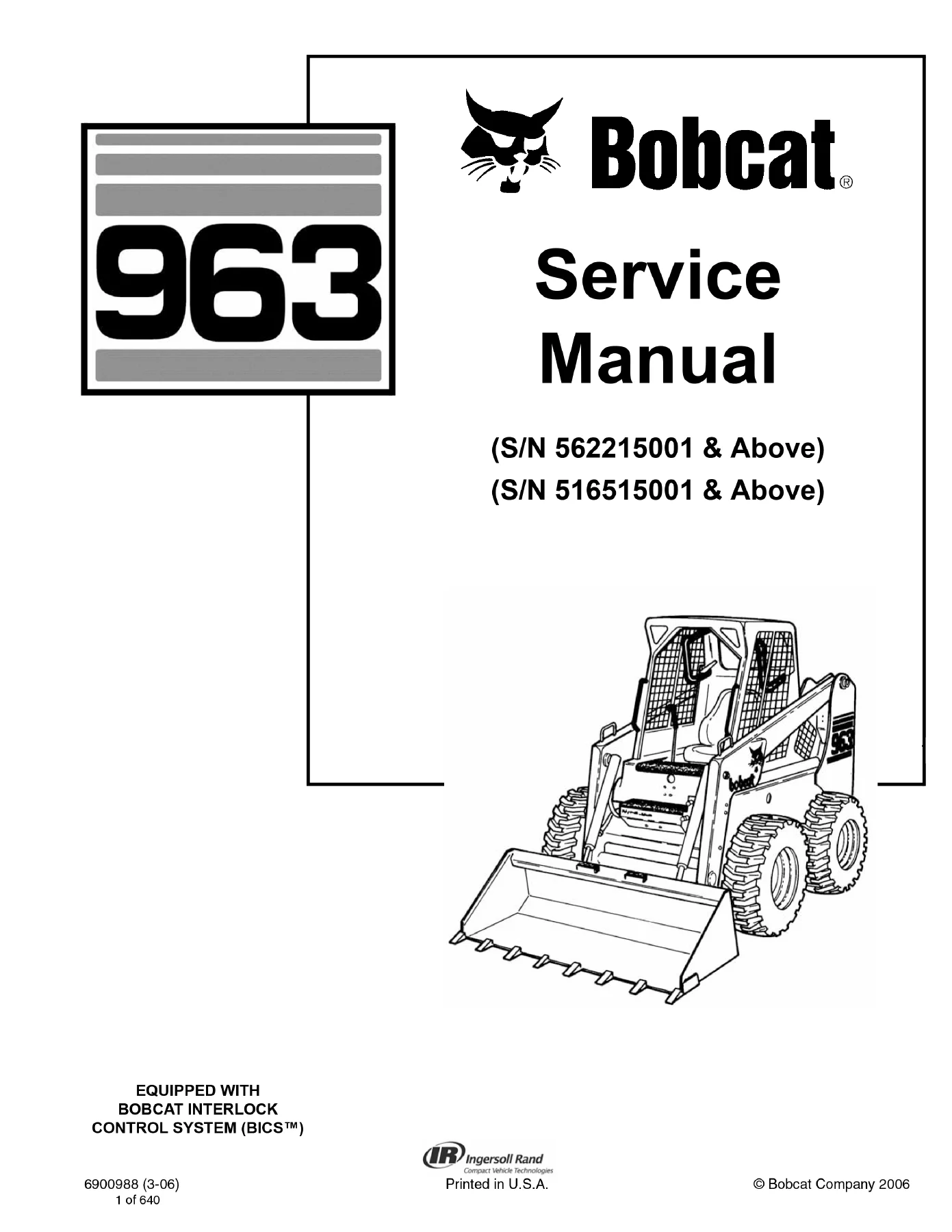
Bobcat 963 Skid-Steer Loader Service Manual - S/N 562215001 & Above / S/N 516515001 & Above — PDF page 1 preview
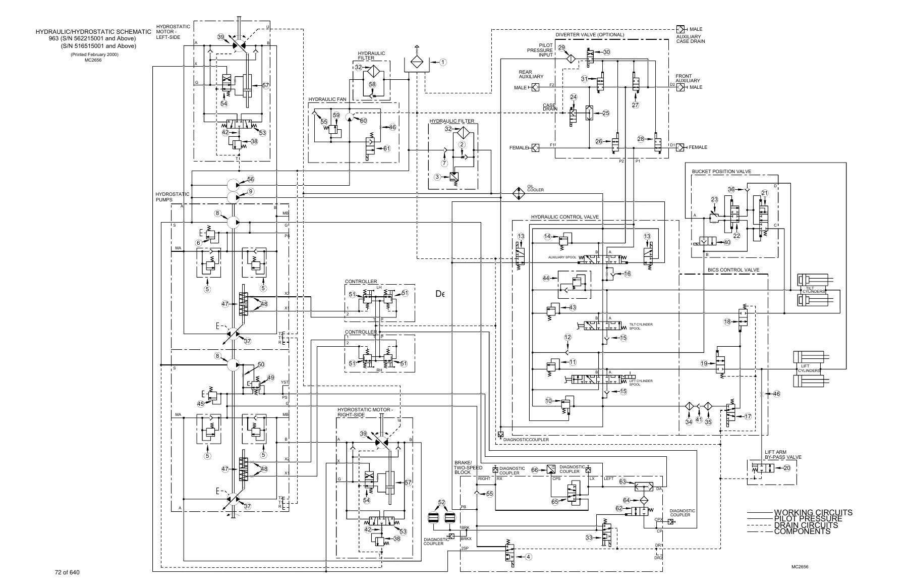
Bobcat 963 Skid-Steer Loader Service Manual - S/N 562215001 & Above / S/N 516515001 & Above — PDF page 72 preview
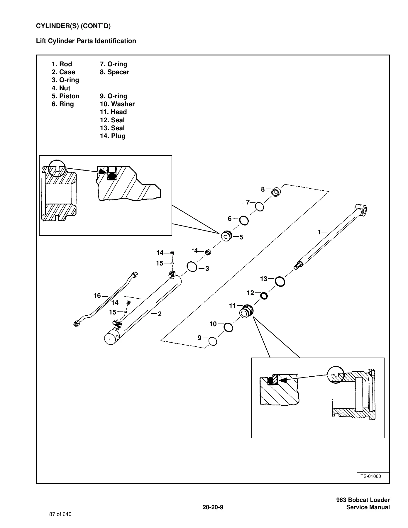
Bobcat 963 Skid-Steer Loader Service Manual - S/N 562215001 & Above / S/N 516515001 & Above — PDF page 87 preview

System schematics and component identification drawings are important parts of the manual. The hydraulic/hydrostatic schematic identifies pumps, motors, cylinders, control valves, BICS-related valves, auxiliary circuits, filters, diagnostic couplers, brake/two-speed components, pressure-control devices, and flow paths. Wiring schematics are provided for the 963 with applicable serial ranges and options. Exploded and parts-identification illustrations appear throughout repair procedures, including detailed lift and tilt cylinder component layouts.

The specification section gives the service data needed to check a repair against the values printed for this machine. Loader performance, hydraulic data, electrical data, capacities, tires, drive-system information, engine dimensions, clearances, pressures, torque values, and hydraulic connection information are consolidated near the end of the manual. Examples of machine-level data shown include rated operating capacity, tipping load, operating weight, travel speeds, hydraulic pump capacity, hydraulic relief settings, fluid capacities, battery and alternator information, and engine performance data. Those values are useful not only during overhaul work but also when confirming whether a system is operating within the manual’s stated limits.

Built for Hands-On Bobcat 963 Repair Work

The Bobcat 963 Skid-Steer Loader Service Manual – S/N 562215001 & Above / S/N 516515001 & Above is suited to owners, workshops, and technicians who need to carry out real service work on the covered 963 loaders: diagnose hydraulic or hydrostatic problems, remove and rebuild components, service the engine and cooling system, trace electrical circuits, work on BICS and machine controls, repair frame and drive components, service HVAC equipment, and verify adjustments against the printed specifications. Using the correct procedure, pressure, clearance, torque, fluid, and serial-number-specific information helps reduce guesswork and supports a more controlled repair process.

After purchase, the manual is supplied as an instant PDF download with no physical shipping. It can be opened on compatible phones, tablets, laptops, and desktop computers and printed when a paper reference is useful at the machine or workbench.
Reviews

There are no reviews yet.

Be the first to review “Bobcat 963 Skid-Steer Loader Service Manual – S/N 562215001 & Above / S/N 516515001 & Above”

What Our Customers Say

★★★★★ Live reviews from customers
Loading customer reviews...
0
    0
    Your Cart
    Your cart is emptyReturn to Shop
    🛒
    Recently Purchased
    🕒 verified order