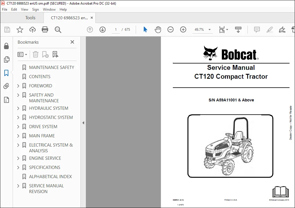
Bobcat CT120 Compact Tractor Service Manual SNA59A11001 & Above – PDF DOWNLOAD
$32.95
Bobcat CT120 Compact Tractor Service Manual SNA59A11001 & Above – PDF DOWNLOAD
Description
Bobcat CT120 Compact Tractor Service Manual SNA59A11001 & Above – PDF DOWNLOAD
FILE DETAILS:
Bobcat CT120 Compact Tractor Service Manual SNA59A11001 & Above – PDF DOWNLOAD
Language : English
Pages : 675
Downloadable : Yes
File Type : PDF
Size:17.6 MB
DESCRIPTION:
Bobcat CT120 Compact Tractor Service Manual SNA59A11001 & Above – PDF DOWNLOAD
FOREWORD
This manual is for the Bobcat compact tractor mechanic. It provides necessary servicing and adjustment procedures for the Bobcat compact tractor and its component parts and systems. Refer to the Operation & Maintenance Manual for operating instructions, starting procedure, daily checks, etc.
SAFETY INSTRUCTIONS:
Instructions are necessary before operating or servicing machine. Read Operation & Maintenance Manual,
Handbook and signs (decals) on machine. Follow warnings and instructions in the manuals when making
repairs, adjustments or servicing. Check for correct function after adjustments, repairs or service. Failure
to follow instructions can cause injury or death.
The following publications provide information on the safe use and maintenance of the loader and attachments:
• The Delivery Report is used to assure that complete instructions have been given to the new owner and that the machine
is in safe operating condition.
• The Operation & Maintenance Manual delivered with the loader gives operating information as well as routin e
maintenance and service procedures. It is a part of the loader and must stay with the machine when it is sold. Replacement
Operation & Maintenance Manuals can be ordered from your Bobcat loader dealer.
• The loader has machine signs (decals) which instruct on the safe operation and care. The signs and their locations are
shown in the Operation & Maintenance Manual. Replacement signs are available from your Bobcat loader dealer.
• The loader has a plastic Operator’s Handbook fastened to the operator cab. Its brief instructions are convenient to the
operator. The Handbook is available from your dealer in an English edition or one of many other languages. See your
Bobcat dealer for more information on translated versions.
• The EMI Safety Manual (available in Spanish) delivered with the loader gives general safety information.
• The Service Manual and Parts Manual are available from your dealer for use by mechanics to do shop–type service and
repair work.
• The Skid–Steer Loader Operator Training Course is available through your local dealer. This course is intended to provide
rules and practices for correct operation of the Bobcat loader. The course is available in English and Spanish version.
• The Bobcat Skid–Steer Loader Safety Video is available from your Bobcat Dealer.
TABLE OF CONTENTS:
Bobcat CT120 Compact Tractor Service Manual SNA59A11001 & Above – PDF DOWNLOAD
MAINTENANCE SAFETY 3
CONTENTS 5
FOREWORD 7
FOREWORD 9
SAFETY INSTRUCTIONS 12
Use Safety Rules 13
Safety Rules For Power Take-Off (PTO) Driven Implements 14
Compact Tractor Requirements and Capabilities 14
FIRE PREVENTION 15
Maintenance 15
Operation 15
Electrical 15
Hydraulic System 15
Fueling 15
Starting 15
Spark Arrestor Exhaust System 15
Welding And Grinding 16
Fire Extinguishers 16
SERIAL NUMBER LOCATIONS 17
Compact Tractor Serial Number 17
Engine Serial Number 17
Loader Serial Number (Optional) 18
DELIVERY REPORT 19
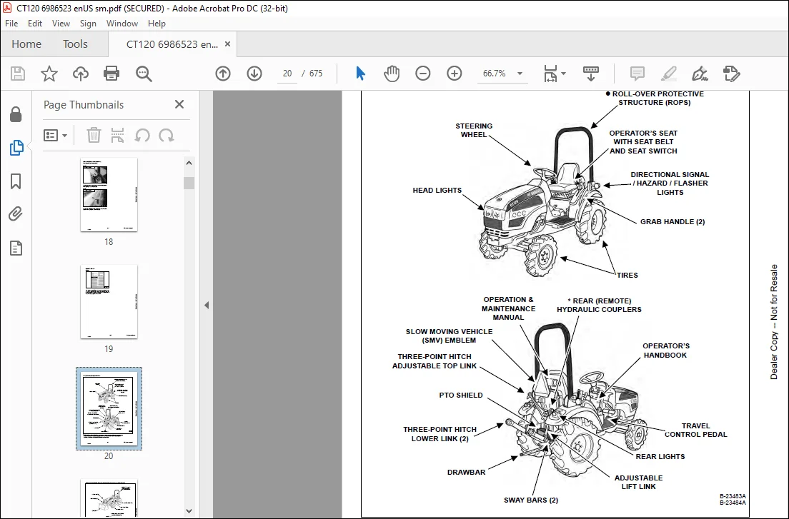
COMPACT TRACTOR IDENTIFICATION 20
COMPACT TRACTOR IDENTIFICATION (WITH OPTIONAL LOADER AND REAR BALLAST) 21
COMPACT TRACTOR IDENTIFICATION (WITH OPTIONAL THREE-POINT IMPLEMENT AND FRONT BALLAST) 22
SAFETY AND MAINTENANCE 23
SUPPORTING THE COMPACT TRACTOR ON JACKSTANDS 27
Procedure 27
ENGINE COVER 29
Opening And Closing 29
SEAT BELT 31
Inspection And Maintenance 31
TRANSPORTING THE COMPACT TRACTOR ON A TRAILER 33
Loading And Unloading 33
Fastening 34
TOWING THE COMPACT TRACTOR 35
Procedure 35
AXLE TOE IN 37
Inspection And Maintenance 37
SERVICE SCHEDULE 39
Chart 39
AIR CLEANER SERVICE 41
Replacing Filter Element 41
ENGINE COOLING SYSTEM 43
Checking Level 43
Cleaning 44
Hoses And Clamps 44
Removing And Replacing Coolant 45
FUEL SYSTEM 47
Fuel Specifications 47
Biodiesel Blend Fuel 47
Filling The Fuel Tank 48
Fuel Filter 49
Removing Air From The Fuel System 50
Filling A Portable Fuel Container 50
ENGINE LUBRICATION SYSTEM 51
Checking And Adding Engine Oil 51
Engine Oil Chart 51
Removing And Replacing Oil And Filter 52
HYDRAULIC / HYDROSTATIC / TRANSMISSION SYSTEM 55
Checking And Adding Fluid 55
Transmission / Differential Fluid Chart 55
Removing And Replacing Hydraulic / Hydrostatic / Transmission Filters 56
Removing And Replacing Hydraulic / Transmission Fluid 57
Hoses And Clamps 57
FRONT AXLE 59
Checking And Adding Lubricant 59
Removing And Replacing Lubricant 60
Axle Pivot 60
SPARK ARRESTOR MUFFLER 61
Cleaning Procedure 61
COMPACT TRACTOR STORAGE AND RETURN TO SERVICE 63
Storage 63
Return To Service 64
ALTERNATOR BELT 65
Belt Adjustment 65
Belt Replacement 65
LUBRICATING THE COMPACT TRACTOR 67
Lubrication Locations 67
TIRE MAINTENANCE 71
Front Wheel Nuts / Bolts 71
Rear Wheel Nuts 71
Mounting 71
Wheel Spacing (AG Tires Only) 72
PIVOT PINS 73
Inspection And Maintenance 73
SAFETY INTERLOCK SYSTEM – NEUTRAL START 75
Inspection And Maintenance 75
SAFETY INTERLOCK SYSTEM – OPERATING 77
Inspection And Maintenance 77
PARKING BRAKE SYSTEM 79
Inspection And Maintenance 79
BRAKE SYSTEM 81
Inspection And Maintenance 81
Adjusting 82
TRAVEL CONTROL PEDAL 83
Inspection And Maintenance 83
Adjustment Procedure 83
CLUTCH SYSTEM 85
Inspection And Maintenance 85
Adjusting 86
Draining Water From Clutch Housing 86
BOB-TACH (HAND LEVER) 87
Inspection And Maintenance 87
HYDRAULIC SYSTEM 89
HYDRAULIC / HYDRAULIC SCHEMATICS 93
HYDRAULIC SYSTEM INFORMATION 95
Glossary Of Hydraulic / Hydrostatic Symbols For Compact Tractors 95
Troubleshooting The Hydraulic Circuit 99
Troubleshooting The Joystick Valve Circuit 99
Troubleshooting The Power Lift Circuit 100
Troubleshooting The Steering Circuit 101
MAIN RELIEF VALVE 103
Testing Information 103
Testing And Adjusting The Main Relief Valve 103
HYDRAULIC PUMP 109
Removal And Installation 109
Parts Identification 110
Disassembly 111
Assembly 113
STEERING VALVE 115
Removal And Installation 115
Parts Identification 117
Disassembly 118
Inspection 123
Assembly 123
STEERING CYLINDER 131
Removal And Installation 131
Parts Identification 132
Disassembly And Assembly 133
RIGHT JOYSTICK (IF EQUIPPED) 135
Removal And Installation 135
Parts Identification 139
Disassembly And Assembly 140
Adjustment 142
RIGHT JOYSTICK VALVE (IF EQUIPPED) 143
Removal And Installation 143
Parts Identification 146
Disassembly 147
Inspection 151
Assembly 151
HYDRAULIC FILTER 155
Description 155
Filter Bracket Removal And Installation 155
OIL COOLER 157
Removal And Installation 157
THREE POINT HITCH HOUSING 159
Removal And Installation 159
AUXILIARY CONTROL VALVE 161
Valve End Cap Removal And Installation 161
Valve Section Parts Identification 163
Valve Section Disassembly And Assembly 164
ROCK SHAFT 171
Removal And Installation 171
Inspection 173
MLS VALVE 175
Removal And Installation 175
Parts Identification 176
Disassembly And Assembly 177
Adjustment 186
THREE POINT CYLINDER 189
Removal And Installation 189
Disassembly And Assembly 190
Inspection 191
THREE POINT CYLINDER CONTROL 193
Removal And Installation 193
FRONT WHEEL DRIVE CASE 199
Removal And Installation 199
Parts Identification 200
Disassembly 201
Assembly 204
ROCK SHAFT LIFT ARMS 209
Removal And Installation 209
FLOW CONTROL VALVE 211
Removal And Installation 211
Parts Identification 213
Disassembly And Assembly 214
CYLINDER (LIFT) (EARLY MODELS) 219
Testing 219
Removal And Installation 219
Parts Identification 222
Disassembly 223
Assembly 225
CYLINDER (LIFT) (LATE MODELS) 229
Testing 229
Removal And Installation 229
Parts Identification 232
Disassembly 233
Assembly 235
CYLINDER (TILT) (EARLY MODELS) 239
Testing 239
Removal And Installation 239
Parts Identification 241
Disassembly 242
Assembly 244
CYLINDER (TILT) (LATE MODELS) 249
Testing 249
Removal And Installation 249
Parts Identification 251
Disassembly 252
Assembly 254
HYDROSTATIC SYSTEM 257
HYDROSTATIC SYSTEM INFORMATION 259
Troubleshooting Chart 259
HYDROSTATIC PUMP 261
Removal And Installation 261
Parts Identification 262
Disassembly 263
Inspection 275
Assembly 277
Hydrostatic Pump Start-Up 289
HYDROSTATIC PUMP TESTING 291
Charge Pressure Testing 291
Forward Drive Relief Testing 292
Reverse Drive Relief Testing 293
DRIVE SYSTEM 295
SERVICE BRAKE 299
Troubleshooting Chart 299
Description 300
Brake Pedal Clearance Adjustment 301
BRAKE PEDAL ASSEMBLY 303
Removal And Installation 303
DRIVESHAFT 305
Removal And Installation 305
AXLE CASE 307
Removal And Installation 307
Parts Identification 310
Disassembly And Assembly 311
BRAKE CASE 317
Removal And Installation 317
Parts Identification 318
Disassembly And Assembly 319
Inspection 323
TRANSMISSION 325
Troubleshooting Chart 325
Middle Case / Output Shaft Group Parts Identification 326
Middle Case / Output Shaft Group Disassembly 327
Middle Case / Output Shaft Group Inspection 332
PTO Driving Shaft Group Parts Identification 333
PTO Driving Shaft Group Disassembly 334
PTO Driving Shaft Group Inspection 335
Differential Parts Identification 336
Differential Disassembly 337
Differential Inspection 341
Pinion Shaft Parts Identification 342
Pinion Shaft Disassembly 343
Pinion Shaft Inspection 347
Range Shifter Shaft Group Parts Identification 348
Range Shifter Shaft Group Disassembly 349
Range Shifter Shaft Group Inspection 351
Mid PTO Shaft Group Parts Identification 352
Mid PTO Shaft Group Disassembly 353
Mid PTO Shaft Group Inspection 356
Rear PTO Group Parts Identification 357
Rear PTO Group Disassembly 358
Rear PTO Group Inspection 362
Rear PTO Group Assembly 364
Mid PTO Shaft Group Assembly 369
Range Shifter Shaft Group Assembly 373
Pinion Shaft Assembly 376
Differential Assembly 380
PTO Driving Shaft Group Assembly 386
Middle Case / Output Shaft Group Assembly 387
FRONT AXLE 393
Removal And Installation 393
AXLE AND DIFFERENTIAL 395
Troubleshooting Chart 395
Gear Case Cover Parts Identification 396
Gear Case Cover Disassembly 397
Gear Case Cover Inspection 400
Axle Case Group Parts Identification 401
Axle Case Group Disassembly 402
Axle Case Group Inspection 408
Axle Support Removal 409
Pinion Shaft Removal 411
Pinion Shaft Parts Identification 412
Pinion Shaft Disassembly 413
Pinion Shaft Inspection 413
Differential Removal 414
Differential Parts Identification 415
Differential Disassembly 416
Differential Inspection 419
Differential Assembly 420
Differential Installation 424
Pinion Shaft Assembly 425
Pinion Shaft Installation 426
Axle Support Installation 428
Axle Case Group Assembly 430
STEERING AXLE ADJUSTMENT 441
Toe-In Checking 441
Toe-In Adjustment 441
Rocking Force 441
Steering Angle Adjustment 442
SEPARATING THE TRACTOR 443
Procedure 443
MAIN FRAME 451
OPERATOR SEAT 453
Removal And Installation 453
CONSOLE COVER 455
Left Side Removal And Installation 455
Right Side Removal And Installation 456
HYDROSTATIC TRANSMISSION CASE 457
Removal And Installation 457
REAR PTO CONTROL 461
Linkage Removal And Installation 461
Disassembly And Assembly 461
MID PTO CONTROL 463
Linkage Removal And Installation 463
Linkage Disassembly And Assembly 463
UPPER COVER 465
Removal And Installation 465
FLOOR MAT 467
Removal And Installation (Right Side) 467
Removal And Installation (Left Side) 467
FLOOR PLATE 469
Removal And Installation (Left Side) 469
Removal And Installation (Right Side) 470
ENGINE COVER 471
Removal And Installation 471
ENGINE SIDE COVER 473
Removal And Installation 473
FENDER 475
Removal And Installation (Right Side) 475
Removal And Installation (Left Side) 476
FIREWALL 479
Removal And Installation 479
ROPS 485
Removal And Installation 485
Bracket Removal And Installation 486
PTO SAFETY SHIELD 487
Removal And Installation 487
DRAW BAR 489
Removal And Installation 489
DRAW BAR ASSEMBLY 491
Removal And Installation 491
THREE POINT HITCH LOWER LINK 493
Left Side Removal And Installation 493
Right Side Removal And Installation 494
Top Link Assembly Removal And Installation 494
FUEL TANK 495
Removal And Installation 495
BOB-TACH (HAND LEVER) 497
Description 497
Removal And Installation 497
Parts Identification 498
Lever And Wedge Disassembly And Assembly 499
ELECTRICAL SYSTEM & ANALYSIS 501
ELECTRICAL SCHEMATIC 503
ELECTRICAL SYSTEM INFORMATION 504
Glossary Of Electrical Symbols 504
Electrical Component Location 507
Troubleshooting 508
Description 509
Fuse And Relay Location – Engine Compartment 509
Fuse And Relay Location – Instrument Panel 510
BATTERY 512
Removing And Installing Battery 512
Battery Maintenance 513
Using A Booster Battery (Jump Starting) 514
ALTERNATOR 516
Belt Adjustment 516
Belt Replacement 516
Charging System Inspection 517
Alternator Voltage Testing 518
Low Voltage Testing 518
High Voltage Testing 519
Removal And Installation 520
Parts Identification 521
STARTER 522
Testing 522
Removal And Installation 523
Parts Identification 524
HOOD LIGHTS 526
Removal And Installation 526
Bulb Removal And Installation 526
REAR LIGHTS 528
Removal And Installation 528
Bulb Removal And Installation 529
TURN INDICATORS 530
Removal And Installation 530
Bulb Removal And Installation 531
SEAT SENSOR 532
Removal And Installation 532
FUEL LEVEL SENDER 534
Removal And Installation 534
INSTRUMENT PANEL 536
Removal And Installation 536
CENTER CONSOLE COVER 540
Removal And Installation 540
PTO SWITCHES 542
Removal And Installation 542
Adjustment 543
HORN 544
Removal And Installation 544
CRUISE CONTROL 546
Inspection And Maintenance 546
Adjusting The Cruise Control Tension 546
ENGINE SERVICE 548
ENGINE INFORMATION 550
Description 550
Specifications (Engine Model C3093B1) 551
Troubleshooting 559
Engine Removal And Installation 562
Compression – Checking 564
ENGINE SPEED CONTROL 566
Cable Removal And Installation 566
Lever Removal And Installation 568
SPARK ARRESTOR MUFFLER 570
Removal And Installation 570
AIR CLEANER 572
Removal And Installation 572
Bracket Removal And Installation 572
ENGINE COOLING SYSTEM 574
Description 574
Radiator Removal And Installation 575
Water Pump Removal And Installation 579
Water Pump Disassembly And Assembly 579
Thermostat Housing Removal And Installation 580
Testing The Thermostat 580
LUBRICATION SYSTEM 582
Description 582
Oil Pan Removal And Installation 583
Oil Pump Removal And Installation 583
Oil Pump Inspection 584
Engine Oil Pressure – Testing 585
Oil Filter 585
FUEL SYSTEM 586
Description 586
Fuel Camshaft Removal And Installation 587
Fuel Shutoff Solenoid Checking 587
Fuel Shutoff Solenoid Removal And Installation 588
Fuel Injection Pump Removal And Installation 589
Fuel Injection Pump Timing 594
Fuel Injector Removal And Installation 597
Fuel Injector Nozzle Pressure – Checking 598
Nozzle Spray Condition 599
Valve Seat Tightness 599
Bleeding The Fuel System 600
CYLINDER HEAD 602
Glow Plug – Testing 602
Glow Plug Removal And Installation 603
Valve Clearance Adjustment 604
Valve Timing – Checking 604
Cylinder Head Removal And Installation 605
Cylinder Head Disassembly And Assembly 608
Cylinder Head Servicing 608
Cylinder Head Top Clearance 609
Valve Guide – Checking 609
Reconditioning The Valve And Valve Seat 611
Valve Spring 612
Valve Tappets 613
Rocker Arm And Shaft – Checking 613
CRANKSHAFT AND PISTONS 614
Piston And Connecting Rod Removal And Installation 614
Piston And Connecting Rod – Servicing 616
Cylinder Bore – Checking 618
Connecting Rod – Alignment 618
Crankshaft And Bearings Removal And Installation 619
Crankshaft And Bearings – Servicing 621
CAMSHAFT AND TIMING GEARS 624
Timing Gearcase Cover Removal And Installation 624
Timing Gears Backlash – Checking 626
Idler Gear And Shaft Removal And Installation 626
Camshaft – Servicing 628
Idler Gear And Shaft – Servicing 629
FLYWHEEL AND HOUSING 630
Flywheel Removal And Installation 630
FAN 632
Removal And Installation 632
CLUTCH ASSEMBLY 634
Removal And Installation 634
Clutch Disc Inspection 634
Pressure Plate Inspection 635
Clutch Pedal Play Adjustment 635
Clutch Pedal Stop Bolt Adjustment 635
CLUTCH HOUSING 636
Removal And Installation 636
Parts Identification 640
Disassembly 641
Inspection 645
Assembly 647
SPECIFICATIONS 652
CT120 COMPACT TRACTOR SPECIFICATIONS 654
Dimensions (Standard Machine) 654
Dimensions (With Optional Loader) 655
Performance 656
Controls 656
Engine 657
Hydraulic System 657
Electrical 657
Power Take-Off (PTO) System (Rear-PTO) 658
Power Take-Off (PTO) System (Mid-PTO Optional) 658
Drive System 658
Steering 658
Capacities 659
Tires 659
Loader (If Equipped) 659
TORQUE SPECIFICATIONS FOR BOLTS 660
Torque For General SAE Bolts 660
Torque For General Metric Bolts 661
TRANSMISSION / DIFFERENTIAL FLUID SPECIFICATIONS 662
Specifications 662
CONVERSIONS 664
Decimal And Millimeter Equivalent Chart 664
U S To Metric Conversion Chart 664
ALPHABETICAL INDEX 666
SERVICE MANUAL REVISION 668
Revision No: CT120-1 668
Revision No: CT120-2 670
Revision No: CT120-3 672
Revision No: CT120-4 674
IMAGES PREVIEW OF THE MANUAL:
Contact us: [email protected]
https://vimeo.com/840831440?share=copy
PLEASE NOTE:
- This is the SAME exact manual used by your dealers to fix your vehicle.
- The same can be yours in the next 2-3 mins as you will be directed to the download page immediately after paying for the manual.
- Any queries / doubts regarding your purchase, please feel free to contact [email protected]
S.M