Bobcat E50 Compact Excavator Service Manual SN AJ1811001 & Above – PDF DOWNLOAD
$34.95
Bobcat E50 Compact Excavator Service Manual SN AJ1811001 & Above – PDF DOWNLOAD
S/N AJ1811001 & Above
Description
Bobcat E50 Compact Excavator Service Manual SN AJ1811001 & Above – PDF DOWNLOAD
FILE DETAILS:
Bobcat E50 Compact Excavator Service Manual SN AJ1811001 & Above – PDF DOWNLOAD
Language : English
Pages :958
Downloadable : Yes
File Type : PDF
DESCRIPTION:
Bobcat E50 Compact Excavator Service Manual SN AJ1811001 & Above – PDF DOWNLOAD
S/N AJ1811001 & Above
FOREWORD
This manual is for the Bobcat excavator mechanic. It provides necessary servicing and adjustment procedures for the Bobcat excavator and its component parts and systems. Refer to the Operation & Maintenance Manual for operating instructions, starting procedure, daily checks, etc.
SAFETY INSTRUCTIONS
Instructions are necessary before operating or servicing machine. Read and understand the Operation & Maintenance Manual, Operator’s Handbook and signs (decals) on machine. Follow warnings and instructions in the manuals when making repairs, adjustments or servicing. Check for correct function after adjustments, repairs or service. Untrained operators and failure to follow instructions can cause injury or death.
The following publications provide information on the safe use and maintenance of the Bobcat machine and attachments:
- The Delivery Report is used to assure that complete instructions have been given to the new owner and that the machine is in safe operating condition.
- The Operation & Maintenance Manual delivered with the machine or attachment contains operating information as well as routine maintenance and service procedures. It is a part of the machine and can be stored in a container provided on the machine. Replacement Operation & Maintenance Manuals can be ordered from your Bobcat dealer.
- Machine signs (decals) instruct on the safe operation and care of your Bobcat machine or attachment. The signs and their locations are shown in the Operation & Maintenance Manual. Replacement signs are available from your Bobcat dealer.
- An Operator’s Handbook fastened to the operator cab. It’s brief instructions are convenient to the operator. The handbook is available from your dealer in an English edition or one of many other languages. See your Bobcat dealer for more information on translated versions.
- The AEM Safety Manual delivered with the machine gives general safety information.
- The Service Manual and Parts Manual are available from your dealer for use by mechanics to do shoptype service and repair work.
IMAGES PREVIEW OF THE MANUAL:
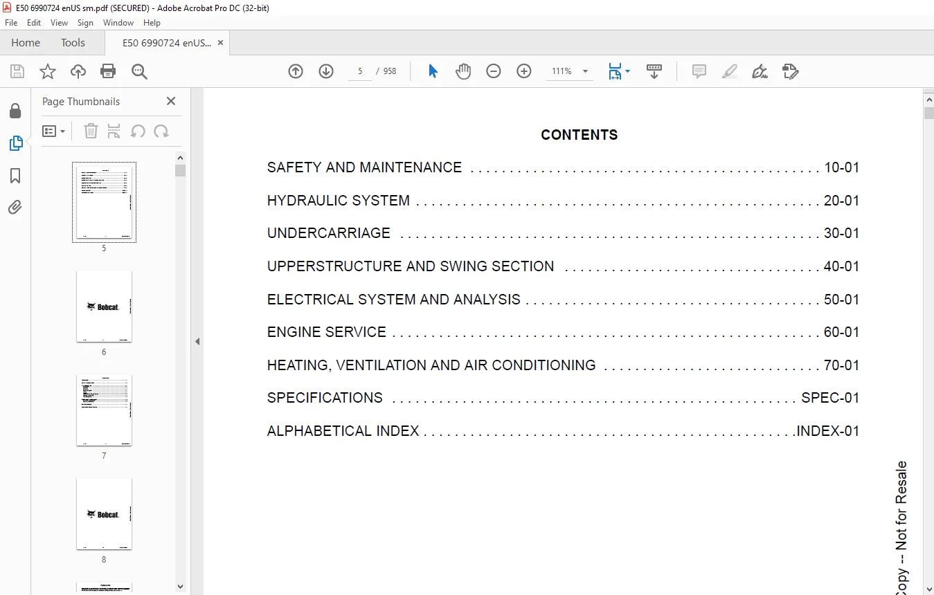
TABLE OF CONTENTS:
Bobcat E50 Compact Excavator Service Manual SN AJ1811001 & Above – PDF DOWNLOAD
MAINTENANCE SAFETY 3
CONTENTS 5
FOREWORD 7
FOREWORD 9
SAFETY INSTRUCTIONS 11
FIRE PREVENTION 13
Maintenance 13
Operation 13
Electrical 13
Hydraulic System 13
Fueling 13
Starting 13
Spark Arrester Exhaust System 13
Welding And Grinding 14
Fire Extinguishers 14
SERIAL NUMBER LOCATIONS 15
Excavator Serial Number 15
Engine Serial Number 15
DELIVERY REPORT 16
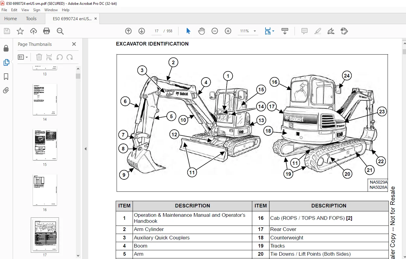
EXCAVATOR IDENTIFICATION 17
SAFETY AND MAINTENANCE 19
LIFTING AND BLOCKING THE EXCAVATOR 23
Procedure 23
LIFTING THE EXCAVATOR 25
Procedure 25
OPERATOR CAB (ROPS / TOPS) 27
Description 27
Cab Door 28
Front Window 29
Front Wiper 30
Window Washer Reservoir 30
Right Side Windows 31
OPERATOR CANOPY (ROPS / TOPS) 33
Description 33
TRANSPORTING THE EXCAVATOR ON A TRAILER 35
Loading And Unloading 35
Fastening 35
TAILGATE 37
Opening And Closing 37
Adjusting The Latch 37
RIGHT SIDE COVER 39
Opening And Closing 39
SERVICE SCHEDULE 41
Maintenance Intervals 41
AIR CLEANER SERVICE 43
Replacing The Filter Elements 43
CAB FILTERS 45
Cleaning And Maintenance 45
ENGINE COOLING SYSTEM 47
Cleaning 47
Checking Level 48
Removing And Replacing Coolant 49
FUEL SYSTEM 51
Fuel Specifications 51
Biodiesel Blend Fuel 51
Filling The Fuel Tank 52
Fuel Filters 53
Removing Air From The Fuel System 54
Draining The Fuel Tank 54
ENGINE LUBRICATION SYSTEM 55
Checking And Adding Engine Oil 55
Engine Oil Chart 55
Removing And Replacing Oil And Filter 56
HYDRAULIC SYSTEM 57
Checking And Adding Hydraulic Oil 57
Hydraulic / Hydrostatic Fluid Chart 58
Removing And Replacing The Hydraulic Filters 58
Removing And Replacing The Hydraulic Fluid 60
LUBRICATING THE EXCAVATOR 61
Lubrication Locations 61
PIVOT PINS 65
Inspection And Maintenance 65
TRAVEL MOTOR 67
Checking And Adding Oil 67
Removing And Replacing Oil 67
EMERGENCY EXIT 69
Right Side Rear Window 69
Front Window 69
SEAT BELT 71
Inspection And Maintenance 71
CONTROL CONSOLE LOCKOUTS 73
Inspection And Maintenance 73
TOWING THE EXCAVATOR 75
Procedure 75
REMOTE START TOOL KIT – MEL1563 77
Remote Start Tool – MEL1563 77
Remote Start Tool – MEL1565 78
Service Tool Harness Communicator – MEL1566 79
REMOTE START TOOL (SERVICE TOOL) KIT – 7217666 81
Description 81
Remote Start Tool (Service Tool) – 7022042 82
Excavator Service Tool Harness – 6689747 83
Computer Service Tool Harness – 6689746 84
HYDRAULIC SYSTEM 85
HYDRAULIC / HYDROSTATIC SCHEMATICS 91
HYDRAULIC SYSTEM INFORMATION 93
Glossary Of Hydraulic / Hydrostatic Symbols 93
Troubleshooting The Hydraulic Circuit 96
Troubleshooting The Cylinder Circuit 97
Troubleshooting The Swing (Upperstructure Slew) Circuit 98
Troubleshooting The Travel Circuit 99
CYLINDER (BOOM) 101
Testing 101
Removal And Installation 103
Parts Identification 106
Disassembly 107
Assembly 110
CYLINDER (ARM) 115
Testing 115
Removal And Installation 117
Parts Identification 119
Disassembly 120
Assembly 122
CYLINDER (BOOM SWING) 127
Testing 127
Removal And Installation 129
Parts Identification 132
Disassembly 133
Assembly 135
CYLINDER (BUCKET) 139
Testing 139
Removal And Installation 141
Parts Identification 143
Disassembly 144
Assembly 146
CYLINDER (BLADE) 149
Testing 149
Removal And Installation 151
Parts Identification 152
Disassembly 153
Assembly 155
CYLINDER (CLAMP) 159
Testing 159
Removal And Installation 160
Parts Identification 162
Disassembly 163
Assembly 166
CYLINDER (ANGLE BLADE) 171
Testing 171
Removal And Installation 172
Parts Identification 174
Disassembly 175
Assembly 177
VALVE (MAIN RELIEF) 181
Testing And Adjusting 181
VALVES (PORT RELIEF) 183
Testing And Adjusting 183
VALVES (CROSS PORT RELIEF) 185
Testing And Adjusting 185
Removal And Installation 188
VALVES (PRESSURE REDUCING) 189
Testing And Adjusting 189
HYDRAULIC CONTROL VALVE 191
Description 191
Removal And Installation 191
Parts Identification 195
Disassembly And Assembly 196
Inlet Valve Section Disassembly And Assembly 200
Boom Swing Valve Section Disassembly And Assembly 204
Slew Valve Section Disassembly And Assembly 207
Blade Valve Section Disassembly And Assembly 211
Right And Left Travel Valve Section Disassembly And Assembly 215
Angle Blade, Boom, Auxiliary, Arm And Bucket Valve Section Disassembly And Assembly 217
HYDRAULIC PUMP 221
Hydraulic Pump Work Sheet 221
Pump Testing 224
Removal And Installation 233
Coupler Removal And Installation 234
Hydraulic Pump Startup 235
Torque Limiter Assembly Parts Identification 236
Torque Limiter Assembly Removal And Installation 237
Torque Limiter Valve Assembly Disassembly And Assembly 237
Pump Control Parts Identification 238
Pump Control Removal And Installation 239
Pump Control Disassembly And Assembly 239
Parts Identification 244
Disassembly And Assembly 245
MANIFOLD ASSEMBLY / ACCUMULATOR (WITHOUT ANGLE BLADE) 253
Description 253
Removal And Installation 253
Parts Identification 255
Disassembly And Assembly 256
MANIFOLD ASSEMBLY / ACCUMULATOR (WITH ANGLE BLADE) 263
Description 263
Removal And Installation 263
Parts Identification 265
Disassembly And Assembly 266
TRAVEL MOTOR 273
Removal And Installation 273
Parts Identification Hydraulic Motor 274
Parts Identification Gear Reduction Hub 275
Disassembly 276
Assembly 286
TRAVEL MOTOR (S/N AJ1817500 & Above) 299
Removal And Installation 299
Parts Identification Hydraulic Motor 300
Parts Identification Gear Reduction Hub 301
Disassembly 302
Assembly 310
SWIVEL JOINT 319
Removal And Installation 319
Parts Identification Straight Blade Swivel (S/N AJ1811001 – AJ1812618) 321
Parts Identification Straight Blade Swivel (S/N AJ1812619 – AJ1913907) 322
Parts Identification Straight Blade Swivel (S/N AJ1813908 & Above) 323
Parts Identification Angle Blade Swivel (S/N AJ11001 – AJ1812637) 324
Parts Identification Angle Blade Swivel (S/N AJ1812638 – AJ1813904) 325
Parts Identification Angle Blade Swivel (S/N AJ1813905 & Above) 326
Disassembly And Assembly 327
SWING MOTOR 329
Removal And Installation 329
Parts Identification 331
Disassembly And Assembly 332
SWING MOTOR (DRIVE CARRIER) 341
Removal And Installation 341
Parts Identification 342
Disassembly And Assembly 343
CONTROL PATTERN SELECTOR VALVE 349
Removal And Installation 349
Parts Identification 350
Disassembly And Assembly 351
RIGHT CONTROL LEVER (JOYSTICK) 353
Testing 353
Handle Removal And Installation 354
Joystick Assembly Removal And Installation 356
Parts Identification 357
Disassembly 358
Assembly 362
LEFT CONTROL LEVER (JOYSTICK) 367
Testing 367
Handle Removal And Installation 368
Joystick Assembly Removal And Installation 370
Parts Identification 371
Disassembly 372
Assembly 376
HYDRAULIC FILTER MOUNT 381
Removal And Installation 381
HYDRAULIC RESERVOIR 383
Removal And Installation 383
OIL COOLER 385
Removal And Installation 385
DIRECT TO TANK VALVE 387
Removal And Installation 387
BLADE CONTROL LEVER 389
Handle Removal And Installation 389
Removal And Installation 391
Parts Identification 393
Disassembly And Assembly 394
CASE DRAIN FILTER MOUNT 399
Removal And Installation 399
TRAVEL CONTROL VALVE 401
Removal And Installation 401
Parts Identification 402
Disassembly And Assembly 403
REMOVING AIR FROM THE HYDRAULIC SYSTEM 409
Procedure 409
MANIFOLD (HYDRAULIC X-CHANGE) (EARLIER MODELS) 411
Removal And Installation 411
Parts Identification 412
Disassembly And Assembly 413
MANIFOLD (HYDRAULIC X-CHANGE) (LATER MODELS) 417
Removal And Installation 417
Parts Identification 418
Disassembly And Assembly 419
MANIFOLD (PIN GRABBER) 425
Removal And Installation 425
Parts Identification 426
Disassembly And Assembly 427
SECONDARY AUXILIARY VALVE (EARLIER MODELS) 429
Removal And Installation 429
Parts Identification 431
Disassembly And Assembly 432
SECONDARY AUXILIARY VALVE (LATER MODELS) 437
Removal And Installation 437
Parts Identification 439
Disassembly And Assembly 440
VALVE (BOOM LOCK) 443
Removal And Installation 443
VALVE (ARM LOCK) 445
Removal And Installation 445
UNDERCARRIAGE 447
BLADE 449
Removal And Installation 449
BLADE (ANGLE) 451
Removal And Installation 451
Cutting Edge Removal And Installation 452
TRACK UNDERCARRIAGE COMPONENTS (RUBBER TRACK) 453
Description 453
Track Lug Height 453
Checking Tension 454
Adjusting Tension 455
Track Removal And Installation 457
Idler Removal And Installation 458
Idler Parts Identification 459
Idler Disassembly 460
Idler Assembly 462
Track Tensioner Removal And Installation 465
Track Tensioner Parts Identification 466
Track Tensioner Disassembly And Assembly 467
Roller Removal And Installation 469
Sprocket Removal And Installation 470
TRACK UNDERCARRIAGE COMPONENTS (STEEL TRACK) 471
Description 471
Checking Tension 472
Adjusting Tension 473
Track Removal 475
Track Installation 478
Idler Removal And Installation 480
Idler Parts Identification 481
Idler Disassembly 482
Idler Assembly 484
Track Tensioner Removal And Installation 487
Track Tensioner Parts Identification 488
Track Tensioner Disassembly And Assembly 489
Roller Removal And Installation 491
Sprocket Removal And Installation 492
Guide Plate Removal And Installation 492
TRACK MAINTENANCE 493
Track Damage Identification 493
SWING CIRCLE GEAR 505
Swing Bearing Removal 505
Swing Bearing Installation 506
UPPERSTRUCTURE AND SWING SECTION 507
UPPERSTRUCTURE 513
Removal 513
Installation 515
ROPS CANOPY 517
Removal And Installation 517
CAB 521
Removal And Installation 521
Door Removal And Installation 524
Front Window Removal And Installation 525
Front Window Disassembly And Assembly 526
Front Window Adjustment 528
Right Side Rear Sliding Window Removal And Installation 530
Right Side Front Sliding Window Removal And Installation 530
Right Side Front And Rear Sliding Window Weather Strip Removal And Installation 531
Right Side Front And Rear Sliding Window Wiper Strip Removal And Installation 531
Glass Removal 532
Glass Installation 533
SEAT 541
Removal And Installation 541
Seat Mount Removal And Installation 542
RIGHT CONSOLE 543
Console Cover Removal And Installation 543
LEFT CONSOLE 547
Lower Console Cover Removal And Installation 547
Upper Console Cover Removal And Installation 547
Compression Spring Removal And Installation 550
Lock Lever Removal And Installation 552
Console Removal And Installation 552
LEFT UPPERSTRUCTURE COVER 553
Removal And Installation 553
RIGHT UPPERSTRUCTURE COVER 555
Removal And Installation 555
COUNTERWEIGHT 557
Removal And Installation 557
Long Arm Counterweight Removal And Installation 560
TRAVEL LEVERS AND PEDALS 561
Removal And Installation 561
Disassembly And Assembly 562
FLOOR MAT 563
Removal And Installation 563
FUEL TANK 565
Removal And Installation 565
Removal And Installation (Cab Equipped Excavator) 566
Fuel Tank Fitting Removal And Installation 566
HORN 567
Removal And Installation 567
SWING FRAME 569
Removal And Installation 569
Boom Swing Frame Hose Routing 572
Bushing Removal 573
Bushing Installation 574
BOOM 575
Removal And Installation 575
STANDARD AND LONG ARM 577
Removal And Installation 577
Arm To Boom Bushing Removal And Installation 578
Arm To Bucket And Bucket Link Bushing Removal And Installation 579
BUCKET 581
Bucket Teeth Removal And Installation 581
Bucket Side Cutting Edge Removal And Installation 582
CLAMP 583
Removal And Installation 583
TAILGATE 585
Removal And Installation 585
Latch Removal And Installation 586
X-CHANGE 587
Removal And Installation 587
Disassembly 588
Assembly 589
X-CHANGE (HYDRAULIC) (EARLIER MODELS) 591
Removal And Installation 591
Parts Identification 593
Disassembly 594
Assembly 599
Expansion Plug Installation 606
X-CHANGE (HYDRAULIC) (LATER MODELS) 607
Removal And Installation 607
Parts Identification 609
Disassembly 610
Assembly 616
Expansion Plug Installation 624
QUICK COUPLER (KLAC™ SYSTEM) 625
Troubleshooting 625
Daily Inspection 625
Removal And Installation 626
Parts Identification 628
Disassembly 629
Assembly 631
QUICK COUPLER (LEHNHOFF® SYSTEM) 633
Troubleshooting 633
Daily Inspection 633
Removal (MS03 And MS08) 634
Installation (MS03 And MS08) 635
Parts Identification (MS03) 636
Disassembly And Assembly (MS03) 637
Parts Identification (MS08) 638
Disassembly (MS08) 639
Assembly (MS08) 642
QUICK COUPLER (PIN GRABBER) 647
Troubleshooting 647
Daily Inspection 648
Removal And Installation 648
Parts Identification 650
Disassembly And Assembly 651
RIGHT SIDE COVER (EARLIER MODELS) 653
Removal And Installation 653
Latch Removal And Installation 654
Latch Adjustment 655
RIGHT SIDE COVER (LATER MODELS) 657
Removal And Installation 657
Latch Removal And Installation 658
Adjustment 658
TOOL BOX 661
Removal And Installation 661
ELECTRICAL SYSTEM AND ANALYSIS 663
ELECTRICAL SCHEMATICS 667
ELECTRICAL SYSTEM INFORMATION 675
Troubleshooting Chart 675
Description 676
Fuse And Relay Location / Identification 676
Shut-Off Switch 678
BATTERY 679
Servicing 679
Maintaining Battery Charge Level 679
Battery Service During Machine Storage 679
Battery Testing 680
Battery Charging 680
Removing And Installing 681
Using A Booster Battery (Jump Starting) 682
ALTERNATOR 683
Belt Adjustment 683
Belt Replacement 683
Charging System Inspection 684
Alternator Voltage Testing 685
Low Voltage Testing 685
High Voltage Testing 686
Removal And Installation 687
Parts Identification 688
STARTER 689
Testing 689
Removal And Installation 690
Parts Identification 691
LIGHTS 693
Removal And Installation 693
Boom Light Removal And Installation 694
Boom Light Bulb Replacement 694
MAGNETIC LOCKOUT SENSOR 695
Removal And Installation 695
FUEL LEVEL SENDER 697
Removal And Installation 697
Testing 698
DIAGNOSTIC SERVICE CODES 699
Viewing Service Codes 699
Service Codes List 700
CONTROL PANEL SETUP 705
Panel Setup (Deluxe Instrument Panel) 705
Password Setup (Keyless Start Panel) 711
Password Setup (Deluxe Instrument Panel) 712
Maintenance Clock 714
INSTRUMENT PANEL 717
Removal And Installation 717
CONTROLLER (GATEWAY AND AUXILIARY) 719
Description 719
Gateway Controller Removal And Installation 719
Auxiliary Controller Removal And Installation 721
ENGINE CONTROL UNIT (ECU) 723
Description 723
Cleaning 724
Removal And Installation 725
KEY SWITCH 727
Removal And Installation 727
WIPER MOTOR 729
Removal And Installation 729
MOTION ALARM SYSTEM 731
Description 731
Inspecting 731
Adjusting Switch Position 732
SERVICE PC (LAPTOP COMPUTER) 733
Connecting The Remote Start Tool 733
Connecting Remote Start Tool (Service Tool) 733
SHUT-OFF SWITCH 735
Description 735
Removal And Installation 736
TRAVEL MOTOR AUTO-SHIFT 739
Auto-Shift Drive System (If Equipped) 739
Troubleshooting 740
AUTO IDLE PRESSURE SENSOR 743
Description 743
Removal And Installation 744
BOBCAT MACHINE IQ WIRELESS COMMUNICATIONS 745
Description 745
Controller Removal And Installation 745
Antenna Removal And Installation 747
Procedure 749
ENGINE SERVICE 751
ENGINE INFORMATION 755
Description 755
Specifications 756
Sensor Location 758
Torque Values 764
Troubleshooting 766
Engine Removal And Installation 768
Compression – Testing (Using Glow Plug Compression Adapter) 776
Compression – Testing (Using Injector Compression Adapter) 778
Injector Signal – Testing 780
Injector Signal – Testing (In-Line) 782
DIESEL OXIDATION CATALYST (DOC) 785
Removal And Installation 785
AIR CLEANER 787
Housing Removal And Installation 787
ENGINE COOLING SYSTEM 789
Radiator Removal And Installation 789
Fan Removal And Installation 792
Water Pump Removal And Installation 793
Thermostat Housing Removal And Installation 794
Testing The Thermostat 795
LUBRICATION SYSTEM 797
Description 797
Oil Pan Removal And Installation 798
Oil Pump Removal And Installation 799
Oil Pump Relief Valve Description 800
Oil Pump Relief Valve Removal And Installation 800
Oil Cooler Removal And Installation 800
Oil Filter Head Removal And Installation 801
Oil Cooler Bypass Description 801
Oil Cooler Bypass Removal And Installation 801
FUEL SYSTEM 803
Description 803
Transfer Pump / High Pressure Pump Removal And Installation 804
Fuel Temperature Sensor Removal And Installation 807
Fuel Cooler Removal And Installation 808
Fuel Bypass Valve Removal And Installation 809
Fuel Recirculation Valve Removal And Installation 810
Fuel Injector Removal And Installation 811
Removing Air From The Fuel System 814
CYLINDER HEAD 815
Glow Plugs Testing 815
Glow Plug Removal And Installation 816
Valve Clearance Adjustment 817
Cylinder Head Removal And Installation 819
Cylinder Head Disassembly And Assembly 823
Cylinder Head Inspection 824
Cylinder Head Top Clearance 825
Valve Step Height 826
Valve Stem Height 826
Valve Guide 827
Valve 827
Valve Spring 828
Rocker Arm Shaft Disassembly And Assembly 829
Rocker Arm Shaft Inspection 830
Push Rod Inspection 830
CRANKSHAFT AND PISTONS 831
Piston And Connecting Rod Removal And Installation 831
Piston And Connecting Rod Inspection 832
Crankshaft Removal And Installation 834
Cylinder Block Inspection 837
Crankshaft Inspection 839
Connecting Rod Inspection 839
Engine Component Class 840
CAMSHAFT 843
Removal And Installation 843
Inspecting 844
GEARCASE 847
Gearcase Cover Removal And Installation 847
Gear Backlash 848
Gear Timing 849
Idle Gear Removal And Installation 850
Idle Gear Inspection 850
TURBOCHARGER 851
Description 851
Removal And Installation 852
Inspection 854
FLYWHEEL AND HOUSING 855
Hydraulic Pump Coupler Removal And Installation 855
Flywheel Removal And Installation 857
Ring Gear Removal And Installation 857
EXHAUST GAS RECIRCULATION (EGR) SYSTEM 859
Removal And Installation 859
INTERCOOLER 863
Description 863
Removal And Installation 863
HEATING, VENTILATION AND AIR CONDITIONING 865
AIR CONDITIONING SYSTEM FLOW 867
Description 867
Chart 868
Components 869
Safety Equipment 872
REGULAR MAINTENANCE 873
Cab Filters 873
Air Conditioning Compressor Belt Adjustment 874
Air Conditioning Compressor Belt Replacement 874
Condenser 875
Air Conditioning Lubrication 875
Evaporator / Heater Coil 875
Air Conditioning Service Chart 877
TROUBLESHOOTING 879
Blower Motor Does Not Operate 879
Blower Motor Operates Normally, But Air Flow Is Insufficient 879
Insufficient Cooling Although Air Flow And Compressor Operation Are Normal 879
The Compressor Operates Improperly Or Not At All 879
Gauge Pressure Related Troubleshooting 880
Temperature / Pressure Chart 881
Poor A/C Performance 882
HVAC Repair And Leaks 882
Electrical System 883
Engine Coolant Bypassing The Heater Valve 885
SYSTEM CHARGING AND RECLAMATION 887
Refrigerant Identification 887
Reclamation And Charging With Recovery / Charging Unit 889
COMPRESSOR 891
Removal And Installation 891
Oil 892
Oil Check 893
CONDENSER 895
Removal And Installation 895
RECEIVER / DRIER 897
Receiver / Drier Removal And Installation 897
Pressure Switch Removal And Installation 898
EVAPORATOR / HEATER UNIT 899
Removal And Installation 899
THERMOSTAT 901
Description 901
Removal And Installation 902
EXPANSION VALVE 905
Removal And Installation 905
EVAPORATOR COIL 907
Removal And Installation 907
HEATER COIL 909
Removal And Installation 909
BLOWER FAN 911
Removal And Installation 911
HEATER VALVE 913
Removal And Installation 913
HVAC DUCT 915
Removal And Installation 915
SPECIFICATIONS 917
EXCAVATOR SPECIFICATIONS 919
Machine Dimensions 919
Machine Dimensions (Standard Arm) 920
Machine Dimensions (Long Arm) 921
Machine Dimensions (Angle Blade) 922
Performance 923
Controls 923
Engine 924
Hydraulic System 925
Hydraulic Cylinders 926
Hydraulic Cycle Times 926
Electrical 927
Drive System 927
Slew System 927
Undercarriage 927
Capacities 928
Tracks 928
Ground Pressure 928
TORQUE SPECIFICATION FOR BOLTS 929
Torque For General SAE Bolts 929
Torque For General Metric Bolts 930
TECHNICAL SERVICE GUIDE SPECIFICATIONS 931
Engine 931
Engine Torques 931
Cooling System 931
Excavator Torques 931
HYDRAULIC CONNECTION SPECIFICATIONS 933
O-ring Face Seal Connection 933
Straight Thread O-ring Fitting 933
Tubelines And Hoses 934
Flare Fitting 934
O-ring Flare Fitting 935
Port Seal Fitting 937
Push To Connect Fittings 938
HYDRAULIC FLUID SPECIFICATIONS 941
Specifications 941
CONVERSIONS 943
Decimal And Millimeter Equivalent Chart 943
U S To Metric Conversion Chart 944
SERVICE TOOLS REQUIRED 945
Remote Start Tools 945
Hydraulic Tools 946
Engine Tools 949
Electrical Tools 951
General Tools 951
HVAC Tools 952
ALPHABETICAL INDEX 953
Contact us: [email protected]
https://vimeo.com/841826351?share=copy
PLEASE NOTE:
- This is the SAME exact manual used by your dealers to fix your vehicle.
- The same can be yours in the next 2-3 mins as you will be directed to the download page immediately after paying for the manual.
- Any queries / doubts regarding your purchase, please feel free to contact [email protected]
S.M