Description
File Details
- Manual type: Service Manual – Compact Excavator
- Brand / model: Bobcat E88
- Serial range: E88 S/N B62N11001 & Above
- Language: English (EN)
- Document number: 46927512enUS (D)
- Date: December 2025
- Page count: 1048
- File format: PDF
The Bobcat E88 Compact Excavator Service Manual S/N B62N11001 & Above 2025 is written for the excavator mechanic. It supplies servicing and adjustment procedures for the machine and its component systems. Operating instructions, starting, and daily checks remain in the Operation & Maintenance Manual; this book is the shop-level companion.
Who This Manual Fits
Coverage is limited to the E88 compact excavator beginning at serial B62N11001. The power unit is the 2.4 L Bobcat Engine, V2, Stage 5 — a four-cylinder, direct-injected, turbocharged and intercooled diesel with 2,392 L (146.0 in³) displacement, closed crankcase ventilation, and glow-plug starting. Gross output is listed at 48,5 kW (65.0 hp) ISO 14396 and 48,7 kW (65.4 hp) SAE J1995, with rated power 48,5 kW (65.0 hp) SAE J1349. Torque figures include 248,0 N·m (182.9 lb-ft) ISO 14396 / rated and 249,2 N·m (183.8 lb-ft) SAE J1995. Low idle is 1200 ± 25 rpm and high idle is 2100 ± 25 rpm.
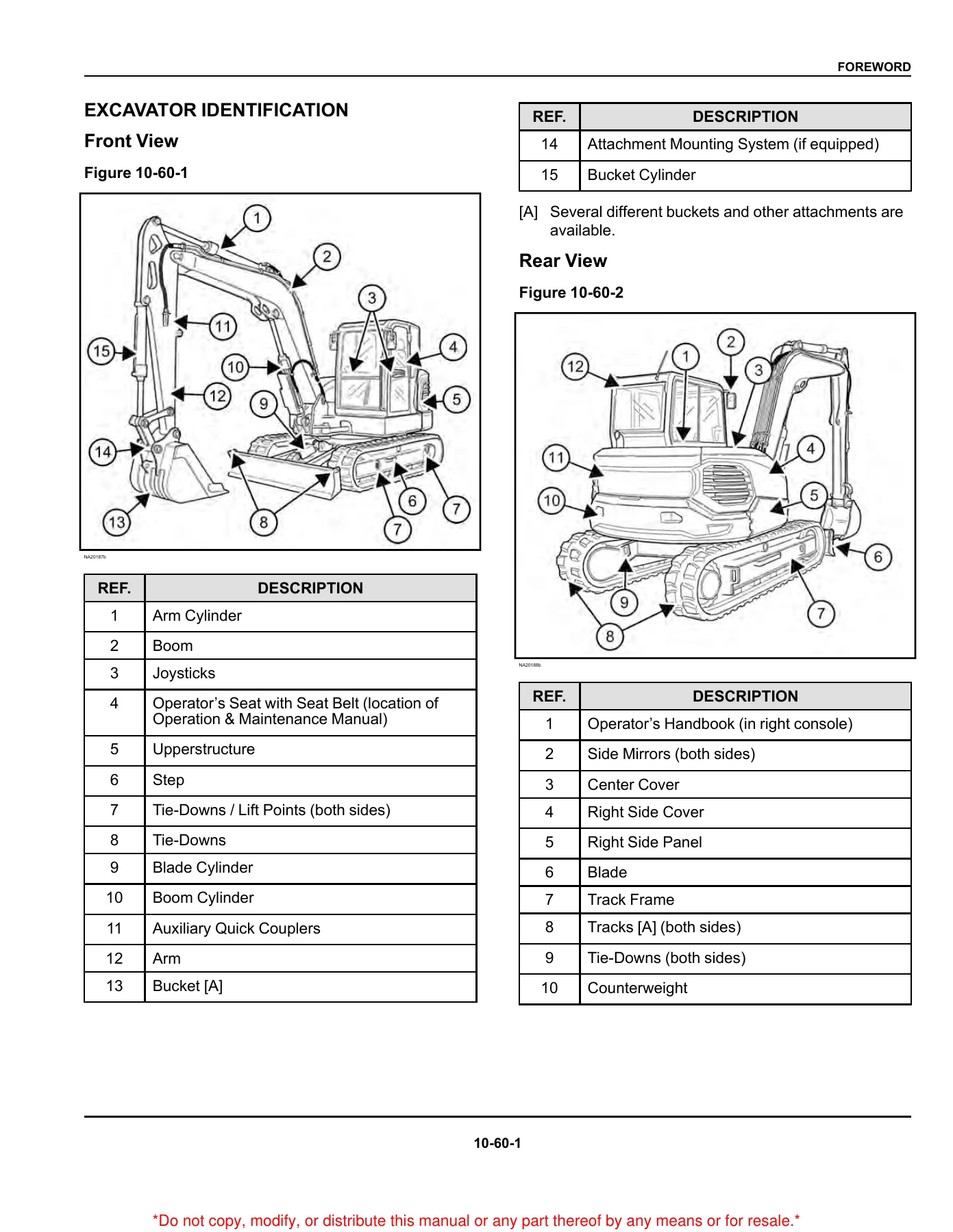
Machine identification plates, engine serial location (side of the engine below the alternator, next to the oil fill tube), front and rear component callouts, and delivery-report requirements are all in the foreword so parts orders and service inquiries can be tied to the correct unit.
Chapters Covered
- Foreword — general inspection; safety instructions; fire prevention; serial number locations; delivery report; excavator identification
- Safety and Maintenance — lifting and blocking; lifting the machine; operator cab (ROPS / TOPS / FOPS); transporting; tailgate and right side cover; service schedule and inspection checkbook; engine air cleaner; cab filters; engine cooling system; fuel system; engine lubrication; hydraulic fluid and filters; machine lubrication and pivot pins; travel motor fluid; emergency exits; seat belt; control console lockouts; towing; Remote Start Tool kit 7217666
- Hydraulic System — system information and troubleshooting; boom, arm, boom swing, bucket, blade, clamp, and articulated-boom cylinders; main, port, and cross-port relief valves; pressure-reducing valves; hydraulic control valve; hydraulic pump testing, coupler, torque limiter, and pump control; air removal
- Undercarriage — blade; rubber track undercarriage; steel / segmented track undercarriage; track components (idler and related parts); track inspection and damage assessment
- Upperstructure and Swing Section — swing and upperstructure service; buckets and teeth; X-Change and quick couplers including German-system hydraulic coupler; covers, toolbox, fuel transfer pump
- Electrical System and Analysis — charging and starting; fuses and relays; instrument and touch displays; ECU; sensors; wiring schematics (E88 S/N B62N11001 & Above)
- Engine Service — engine information, sensors, torque values, troubleshooting, engine R&I; compression, injector signal, and turbo oil-pressure tests; DPF regeneration and R&I; air cleaner housing; cooling package, fan, water pump, thermostat; lubrication system; fuel system including injectors and coding; cylinder head and valve work; crankshaft and pistons; camshaft; gear case; turbocharger; flywheel and housing; EGR
- Heating, Ventilation, and Air Conditioning (HVAC) — system flow and components; maintenance and belt service; troubleshooting; reclaim and charge; compressor, condenser, receiver/drier, evaporator/heater, expansion valve, blower, heater valve, control panel, ducts; Auto HVAC and ATM codes
- Specifications — machine dimensions; rated lift capacity (long arm, standard arm, add-on counterweight, articulated boom); excavator, engine, hydraulic, electrical, drive, slew, undercarriage, capacity, track, ground-pressure, and environmental data; technical service-guide specs and torques; hydraulic connections and fluid; conversions; service tools
Taken together, the Bobcat E88 service manual walks a technician from daily and interval maintenance through circuit diagnosis, component R&I, cylinder and pump rebuild-level work, engine overhaul measurements, emissions-system service, cab HVAC repair, and the numeric limits needed to set the machine back to specification.
Hydraulic Work You Can Carry Out
Section 30 starts with a symbol glossary and separate troubleshooting trees for the hydraulic circuit, cylinder circuit, slew circuit, and travel circuit. Each work-group cylinder — boom (standard and articulated-boom machines), arm, boom swing, bucket, blade, clamp, and articulated boom — has leak-down testing, pin-off and hose isolation steps, parts identification, disassembly, and assembly. Relief hardware is treated as its own group: main relief description, port-relief pressure test and adjust, cross-port relief with gauge-port specifications, and the pressure-reducing valve used for pilot supply.
Complete PDF Bookmark Tree
Complete Bookmarks
The complete bookmarks in the “Bobcat E88 Compact Excavator Service Manual S/N B62N11001 & Above 2025” are as follows:
MAINTENANCE SAFETY WARNINGSp. 2
MAINTENANCE SAFETY WARNINGSp. 3
CONTENTSp. 5
+FOREWORDp. 7
+FOREWORDp. 9
+SAFETY INSTRUCTIONSp. 11
Before Operationp. 11
Safe Operation Is The Operator’s Responsibilityp. 11
Safe Operation Needs A Qualified Operatorp. 11
A Qualified Operator Must Do The Followingp. 12
Silica Dust Exposurep. 12
+FIRE PREVENTIONp. 13
Maintenancep. 13
Operationp. 13
Electricalp. 13
Hydraulic Systemp. 13
Fueling (Diesel)p. 13
Startingp. 13
Exhaust Systemp. 13
Welding And Grindingp. 13
Fire Extinguishersp. 14
+SERIAL NUMBER LOCATIONSp. 15
Machine Serial Number Locationp. 15
Engine Serial Number Locationp. 15
DELIVERY REPORTp. 17
+EXCAVATOR IDENTIFICATIONp. 19
Front Viewp. 19
Rear Viewp. 19
+SAFETY AND MAINTENANCEp. 21
+LIFTING AND BLOCKING THE MACHINEp. 23
Lifting And Blocking The Machinep. 23
+LIFTING THE MACHINEp. 25
+OPERATOR CAB (ROPS / TOPS / FOPS)p. 27
Operating The Cab Doorp. 27
Operating The Front Windowp. 28
Operating The Right Windowsp. 29
Operating The Cab Interior Lightp. 29
Operating Windshield Wiperp. 29
Window Washer Reservoirp. 30
Heating, Ventilation, And Air Conditioning Ductingp. 30
+TRANSPORTING THE MACHINEp. 31
Fastening The Machine To A Trailerp. 31
+TAILGATEp. 33
Opening And Closing The Tailgatep. 33
+RIGHT SIDE COVERp. 35
Opening And Closing The Right Side Coverp. 35
+SERVICE SCHEDULEp. 37
Maintenance Intervalsp. 37
Service Schedulep. 37
Inspection Checkbookp. 41
+ENGINE AIR CLEANERp. 43
Replacing The Outer Filter Of The Air Cleanerp. 43
Replacing The Inner Filter Of The Air Cleanerp. 43
+CAB FILTERSp. 45
Cleaning And Maintaining The Recirculation Filterp. 45
Cleaning And Maintaining The Fresh Air Filterp. 45
+ENGINE COOLING SYSTEMp. 47
Cleaning The Engine Cooling Systemp. 47
Coolant Typesp. 47
+Coolant Concentrationp. 47
Propylene Glycol (PG) Concentrationp. 47
Ethylene Glycol (EG) Concentrationp. 48
Checking Coolant Levelp. 48
Replacing Coolantp. 48
+FUEL SYSTEMp. 51
+Fuel Specificationsp. 51
U.S. Standard (ASTM D975)p. 51
E.U. Standard (EN590)p. 51
Biodiesel Blend Fuelp. 51
Filling The Fuel Tankp. 52
Using The Fuel Fill Pumpp. 52
Removing Water From The Fuel Filterp. 53
Replacing The Fuel Filterp. 54
Replacing The Fuel Pre-Filterp. 55
Replacing The Fuel Tank Vent Filterp. 55
+ENGINE LUBRICATION SYSTEMp. 57
Checking And Adding Engine Oilp. 57
Engine Oil Chartp. 57
Replacing Engine Oil And Filterp. 57
+HYDRAULIC SYSTEMp. 59
Checking And Adding Hydraulic Fluidp. 59
Hydraulic Fluid Chartp. 60
Hydraulic Fluid Colorsp. 60
Replacing The Hydraulic Filterp. 61
Replacing The Case Drain Filterp. 61
Replacing Hydraulic Fluidp. 62
Checking The Fluid Level Of The Swing Motor Gear Boxp. 63
Replacing Swing Motor Gear Box Fluidp. 63
+MACHINE LUBRICATIONp. 65
Grease Fitting Locationsp. 65
+Lubricate As Indicatedp. 65
Blade Cylinderp. 65
Boom Basep. 65
Bucket, Arm, and Boomp. 66
Articulated Boom (If Equipped)p. 66
Remote Lubricationp. 66
+PIVOT PINSp. 69
Pivot Pin Inspection And Maintenancep. 69
+TRAVEL MOTORp. 71
Checking And Adding Travel Motor Fluidp. 71
Replacing Travel Motor Fluidp. 71
+EMERGENCY EXITSp. 73
Emergency Exit Locationsp. 73
Making An Emergency Exit Through The Front Windowp. 73
Making An Emergency Exit Through The Right Side Windowp. 73
+SEAT BELTp. 75
Inspecting And Maintaining The Seat Beltp. 75
+CONTROL CONSOLE LOCKOUTSp. 77
Inspecting And Maintaining The Control Console Lockoutsp. 77
+TOWING THE MACHINEp. 79
+REMOTE START TOOL (SERVICE TOOL) KIT – 7217666p. 81
Remote Start Tool (Service Tool) Kit — 7217666 Descriptionp. 81
Remote Start Tool (Service Tool) – 7022042p. 81
Excavator Service Tool Harness – 6689747p. 81
Computer Service Tool Harness – 6689746p. 82
+HYDRAULIC SYSTEMp. 85
+HYDRAULIC / HYDROSTATIC SCHEMATICSp. 91
S/N B62N11001 & Abovep. 91
+HYDRAULIC SYSTEM INFORMATIONp. 93
+Glossary Of Hydraulic / Hydrostatic Symbolsp. 93
Glossary Of Hydraulic / Hydrostatic Symbolsp. 93
Troubleshooting The Hydraulic Circuitp. 97
Troubleshooting The Cylinder Circuitp. 98
Troubleshooting The Slew (Upperstructure Slew) Circuitp. 99
Troubleshooting The Travel Circuitp. 100
+CYLINDER (BOOM)p. 103
Testing The Boom Cylinderp. 103
Removing And Installing the Boom Cylinderp. 104
Boom Cylinder Parts Identificationp. 108
Disassembling The Boom Cylinderp. 109
Assembling The Boom Cylinderp. 115
+CYLINDER BOOM (WITH ARTICULATED BOOM)p. 123
Testing The Boom (With Articulated Boom) Cylinderp. 123
Removing And Installing The Boom (With Articulated Boom) Cylinderp. 124
Boom Cylinder Parts Identificationp. 128
Disassembling The Boom Cylinderp. 129
Assembling The Boom Cylinderp. 135
+CYLINDER (ARM)p. 143
Testing The Arm Cylinderp. 143
Removing And Installing The Arm Cylinderp. 144
Arm Cylinder Parts Identificationp. 146
Disassembling The Arm Cylinderp. 147
Assembling The Arm Cylinderp. 153
+CYLINDER ARM (WITH ARTICULATED BOOM)p. 161
Testing The Arm (With Articulated Boom) Cylinderp. 161
Removing And Installing The Arm (With Articulated Boom) Cylinderp. 162
Arm Cylinder Parts Identificationp. 166
Disassembling The Arm Cylinderp. 167
Assembling The Arm Cylinderp. 173
+CYLINDER (BOOM SWING)p. 181
Testing The Boom Swing Cylinderp. 181
Removing And Installing The Boom Swing Cylinderp. 181
Boom Swing Cylinder Parts Identificationp. 184
Disassembling The Boom Swing Cylinderp. 185
Assembling The Boom Swing Cylinderp. 187
+CYLINDER (BUCKET)p. 191
Testing The Bucket Cylinderp. 191
Removing And Installing The Bucket Cylinderp. 191
Bucket Cylinder Parts Identificationp. 194
Disassembling The Bucket Cylinderp. 195
Assembling The Bucket Cylinderp. 201
+CYLINDER (BLADE)p. 209
Removing The Blade Cylinder Cover (Version Three)p. 209
Testing The Blade Cylinderp. 209
Removing And Installing The Blade Cylinderp. 209
Blade Cylinder Parts Identificationp. 212
Disassembling The Blade Cylinderp. 213
Assembling The Blade Cylinderp. 217
+CYLINDER (CLAMP)p. 223
Testing The Clamp Cylinderp. 223
Removing And Installing The Clamp Cylinderp. 223
Clamp Cylinder Parts Identificationp. 226
Disassembling The Clamp Cylinderp. 227
Assembling The Clamp Cylinderp. 229
+CYLINDER (ARTICULATED BOOM)p. 235
Testing The Articulated Boom Cylinderp. 235
Removing And Installing The Articulated Boom Cylinderp. 236
Articulated Boom Cylinder Parts Identificationp. 240
Disassembling The Articulated Boom Cylinderp. 241
Assembling The Articulated Boom Cylinderp. 245
+VALVE (MAIN RELIEF)p. 251
Description Of The Main Relief Valvep. 251
+VALVE (PORT RELIEF)p. 253
Testing And Adjusting The Port Relief Valve Pressurep. 253
+VALVE (CROSS PORT RELIEF)p. 255
Testing And Adjusting The Cross Port Relief Valve Pressurep. 255
System Press At Gauge Port Specificationsp. 257
Removing and Installing The Cross Port Relief Valvep. 257
+VALVES (PRESSURE REDUCING)p. 259
Testing And Adjusting The Pressure Reducing Valvep. 259
+HYDRAULIC CONTROL VALVEp. 261
Description Of The Hydraulic Control Valvep. 261
Removing And Installing The Hydraulic Control Valvep. 261
Hydraulic Control Valve Parts Identificationp. 266
Disassembling And Assembling The Hydraulic Control Valvep. 267
Disassembling And Assembling The Inlet Valve Sectionp. 270
Disassembling And Assembling The Valve Sectionp. 272
+HYDRAULIC PUMPp. 277
Hydraulic Pump Worksheetp. 277
+Pump Testingp. 279
Hydraulic Pump Test Fitting Installationp. 279
Adjusting The Minimum Displacementp. 281
Adjusting The Torque Limiter Supply Pressurep. 284
Adjusting The Pump Margin Pressurep. 285
Adjusting The Load Sense Relief Valvep. 287
Adjusting The Torque Limiterp. 288
Removing And Installing The Hydraulic Pumpp. 290
Removing And Installing The Couplerp. 292
Hydraulic Pump Startupp. 293
Removing And Installing The Torque Limiter Valvep. 294
Torque Limiter Valve Parts Identificationp. 296
Disassembling The Torque Limiter Valvep. 297
Assembling The Torque Limiter Valvep. 300
Initial Setting Of The Torque Limiter Valvep. 303
Removing And Installing The Pump Controlp. 305
Pump Control Parts Identificationp. 308
Disassembling And Assembling The Pump Margin Controlp. 309
Disassembling And Assembling The Torque Limiter Supply Controlp. 310
Hydraulic Pump Parts Identificationp. 314
Disassembling The Hydraulic Pumpp. 315
Assembling The Hydraulic Pumpp. 323
+MANIFOLD ASSEMBLY / ACCUMULATOR (WITH FIXED BOOM)p. 333
Description Of The Manifold / Accumulator (With Fixed Boom)p. 333
Removing And Installing The Manifold / Accumulatorp. 333
Manifold Assembly / Accumulator (With Fixed Boom) Parts Identificationp. 336
Disassembling And Assembling The Manifold Assembly / Accumulatorp. 337
+MANIFOLD ASSEMBLY / ACCUMULATOR (WITH ARTICULATED BOOM)p. 345
Description Of The Manifold / Accumulator (With Articulated Boom)p. 345
Removing And Installing The Manifold / Accumulatorp. 345
Manifold Assembly / Accumulator (With Articulated Boom) Parts Identificationp. 348
Disassembling And Assembling The Manifold Assembly / Accumulator (With Articulated Boom)p. 349
+TRAVEL MOTORp. 355
Travel Motor Descriptionp. 355
Removing And Installing The Travel Motorp. 355
Hydraulic Motor Parts Identificationp. 358
Gear Reduction Hub Parts Identificationp. 360
Disassembling The Travel Motorp. 361
Assembling The Travel Motorp. 374
+SWIVEL JOINT (STANDARD BLADE)p. 391
Removing And Installing The Swivel Jointp. 391
Swivel Joint Parts Identificationp. 392
Disassembling And Assembling The Swivel Jointp. 393
+SLEW MOTORp. 397
Removing And Installing The Slew Motorp. 397
Slew Motor Parts Identificationp. 400
Disassembling And Assembling The Slew Motorp. 401
+SLEW MOTOR (DRIVE CARRIER)p. 411
Removing And Installing The Slew Motor (Drive Carrier)p. 411
Slew Motor (Drive Carrier) Parts Identificationp. 412
Disassembling And Assembling The Slew Motor (Drive Carrier)p. 413
+JOYSTICK PATTERN SELECTOR VALVEp. 417
Removing And Installing The Joystick Pattern Selector Valvep. 417
Joystick Pattern Selector Valve Parts Identificationp. 418
Disassembling And Assembling The Joystick Pattern Selector Valvep. 419
+RIGHT CONTROL LEVER (JOYSTICK)p. 421
Testing The Control Lever (Joystick)p. 421
Removing And Installing The Right Control Lever (Joystick) Handlep. 421
Removing And Installing The Joystick Assemblyp. 423
Right Control Lever (Joystick) Parts Identificationp. 426
Disassembling The Right Control Lever (Joystick)p. 427
Assembling The Right Control Lever (Joystick)p. 430
+LEFT CONTROL LEVER (JOYSTICK)p. 435
Testing The Control Lever (Joystick)p. 435
Removing And Installing The Left Control Lever (Joystick) Handlep. 435
Removing And Installing The Left Control Lever (Joystick) Assemblyp. 437
Left Control Lever (Joystick) Parts Identificationp. 440
Disassembling The Left Control Lever (Joystick)p. 441
Assembling The Left Control Lever (Joystick)p. 444
+HYDRAULIC FILTER MOUNTp. 449
Removing And Installing The Hydraulic Filter Mountp. 449
+HYDRAULIC RESERVOIRp. 451
Removing And Installing The Hydraulic Reservoirp. 451
+OIL COOLERp. 455
Oil Cooler Descriptionp. 455
Removing And Installing The Oil Coolerp. 455
+BLADE CONTROL LEVERp. 457
Removing And Installing The Blade Control Lever Handlep. 457
Removing And Installing The Blade Control Leverp. 458
Blade Control Lever Parts Identification (Standard Blade)p. 460
Blade Control Lever Parts Identification (4th Auxiliary)p. 462
Disassembling And Assembling The Blade Control Leverp. 463
+CASE DRAIN FILTER MOUNTp. 469
Removing And Installing The Case Drain Filter Mountp. 469
+TRAVEL CONTROL VALVEp. 471
Removing And Installing The Travel Control Valvep. 471
Travel Control Valve Parts Identificationp. 472
Disassembling And Assembling The Travel Control Valvep. 473
+VALVE (ARTICULATED BOOM)p. 479
Removing And Installing The Articulated Boom Valvep. 479
Articulated Boom Valve Parts Identificationp. 480
Disassembling And Assembling The Articulated Boom Valvep. 481
+REMOVING AIR FROM HYDRAULIC SYSTEMp. 485
Removing Air From The Hydraulic Systemp. 485
+MANIFOLD (PIN GRABBER)p. 487
Removing And Installing The Manifold (Pin Grabber)p. 487
Manifold (Pin Grabber) Parts Identificationp. 488
Disassembling And Assembling The Manifold (Pin Grabber)p. 489
+SECONDARY AUXILIARY VALVEp. 493
Removing And Installing The Secondary Auxiliary Valvep. 493
Secondary Auxiliary Valve Parts Identificationp. 496
Disassembling And Assembling The Secondary Auxiliary Valvep. 497
+VALVE (BOOM LOCK)p. 501
Removing And Installing The Boom Lock Valvep. 501
+VALVE (ARM LOCK)p. 503
Removing And Installing The Arm Lock Valvep. 503
+VALVE (ARTICULATED BOOM LOCK)p. 505
Removing And Installing The Articulated Boom Lock Valvep. 505
+VALVE (CLAMP DIVERTER)p. 507
Removing And Installing The Clamp Diverter Valvep. 507
+UNDERCARRIAGEp. 509
+BLADEp. 511
Removing And Installing The Bladep. 511
+TRACK UNDERCARRIAGE (RUBBER TRACK)p. 513
Descriptionp. 513
Track Lug Heightp. 513
Checking And Adjusting Track Tension (Rubber Track)p. 513
Removing And Installing The Track (Rubber Track)p. 515
+TRACK UNDERCARRIAGE (STEEL / SEGMENTED TRACK)p. 517
Descriptionp. 517
Checking And Adjusting Track Tension (Steel / Segmented Track)p. 517
Removing The Steel / Segmented Trackp. 518
Installing The Steel / Segmented Trackp. 520
Removing And Installing The Steel / Segmented Guide Platep. 521
+TRACK UNDERCARRIAGE COMPONENTSp. 523
Removing And Installing The Idlerp. 523
Removing And Installing The Track Tensionerp. 523
Track Tensioner Parts Identificationp. 526
Disassembling And Assembling The Track Tensionerp. 527
Removing And Installing The Rollersp. 527
Removing And Installing The Sprocketp. 528
Removing And Installing The Rubber Padp. 528
Removing And Installing The Steel Shoep. 529
+TRACK MAINTENANCEp. 531
+Track Damage Identificationp. 531
Cutting Of Steel Cordsp. 531
Abrasion Of Embedded Metalsp. 532
Separation Of Embedded Metalsp. 532
Separation Of Embedded Metals Due To Corrosionp. 533
Cuts On The Lug Side Rubberp. 534
Cracks On The Lug Side Rubber Due To Fatiguep. 535
Lug Abrasionp. 536
Cracks And Cuts On The Lug Side Rubberp. 536
Abrasion Of The Track Roller Sidep. 537
Cuts On The Edges Of Track Roller Sidep. 538
+SLEW CIRCLE GEARp. 541
Removing The Slew Bearingp. 541
Installing The Slew Bearingp. 541
+UPPERSTRUCTURE AND SWING SECTIONp. 543
+UPPERSTRUCTUREp. 547
Removing The Upperstructurep. 547
Installing The Upperstructurep. 548
+CABp. 551
ROPS / Canopy Lifting Tool Dimensionsp. 551
Removing And Installing The Cabp. 552
Removing And Installing The Doorp. 555
Removing And Installing The Door Latchp. 555
Removing And Installing The Hold Open Latchp. 556
Removing And installing The Front Windowp. 557
Disassembling And Assembling The Front Windowp. 559
Removing And Installing the Right Side Sliding Windowp. 559
Removing The Glassp. 561
Installing The Glassp. 562
+SEATp. 563
Removing And Installing The Seatp. 563
+RIGHT CONSOLEp. 565
Removing And Installing The Right Console Coverp. 565
+LEFT CONSOLEp. 569
Removing And Installing The Lower Console Coverp. 569
Removing And Installing The Upper Left Console Coverp. 569
Removing And Installing The Compression Springp. 571
Removing And Installing The Left Console Lock Leverp. 573
Removing And Installing The Left Consolep. 573
+LEFT SIDE PANELp. 575
Removing And Installing The Left Side Panelp. 575
+RIGHT SIDE PANELp. 577
Removing And Installing The Right Side Panelp. 577
+COUNTERWEIGHTp. 579
Removing And Installing The Counterweightp. 579
Removing And Installing The Add-on Counterweightp. 581
+TRAVEL LEVER AND PEDALSp. 583
Removing And Installing The Travel Levers And Pedalsp. 583
Removing And Installing The Articulated Boom Pedalp. 583
Disassembling And Assembling The Travel Levers And Pedalsp. 583
+FLOORPLATEp. 585
Removing And Installing The Floorplatep. 585
+FUEL TANKp. 587
Removing And Installing The Fuel Tankp. 587
+HORNp. 589
Removing And Installing The Hornp. 589
+SWING FRAMEp. 591
Removing And Installing The Swing Framep. 591
Removing The Swing Frame Bushingp. 592
Installing The Swing Frame Bushingp. 593
+BOOMp. 595
Removing And Installing The Boomp. 595
+ARTICULATED BOOMp. 597
Removing And Installing The Articulated Boomp. 597
+ARMp. 601
Removing And Installing The Armp. 601
Removing And Installing The Arm To Boom Bushingp. 602
Removing And Installing The Arm To Bucket And Bucket Link Bushingp. 602
+BUCKETp. 605
Replacing Bucket Teeth (Heavy Duty Bucket)p. 605
Replacing Bucket Teeth (Severe Duty Bucket)p. 605
+CLAMPp. 607
Removing And Installing The Clampp. 607
+TAILGATEp. 609
Removing And Installing The Tailgatep. 609
Removing And Installing The Tailgate Latchp. 609
+QUICK COUPLER (PIN GRABBER) (EARLIER MODEL)p. 611
Troubleshooting The Quick Coupler (Pin Grabber)p. 611
Daily Inspection Of The Quick Coupler (Pin Grabber)p. 612
Removing And Installing The Quick Coupler (Pin Grabber)p. 612
Quick Coupler (Pin Grabber) Parts Identificationp. 614
Disassembling And Assembling The Quick Coupler (Pin Grabber)p. 615
+QUICK COUPLER (PIN GRABBER) (LATER MODEL)p. 619
Troubleshooting The Quick Coupler (Pin Grabber)p. 619
Daily Inspection Of The Quick Coupler (Pin Grabber)p. 620
Removing And Installing The Quick Coupler (Pin Grabber)p. 620
Quick Coupler (Pin Grabber) Parts Identificationp. 622
Disassembling And Assembling The Quick Coupler (Pin Grabber)p. 623
+QUICK COUPLER (KLAC™ SYSTEM)p. 627
Troubleshooting The Quick Coupler (KLAC™ System)p. 627
Daily Inspection Of The Quick Coupler (KLAC™ System)p. 627
Removing And Installing The Quick Coupler (KLAC™ System)p. 627
Quick Coupler (KLAC™ System) Parts Identificationp. 630
Disassembling The Quick Coupler (KLAC™ System)p. 631
Assembling The Quick Coupler (KLAC™ System)p. 632
+QUICK COUPLER (GERMAN SYSTEM)p. 635
Troubleshooting The German System Quick Couplerp. 635
German System Quick Coupler Daily Inspectionp. 635
Removing The German System Quick Coupler (MS03 And MS08)p. 635
Installing The German System Quick Coupler (MS03 And MS08)p. 636
German System Quick Coupler Parts Identification (MS03)p. 638
Disassembling And Assembling The German System Quick Coupler (MS03)p. 639
German System Quick Coupler Parts Identification (MS08)p. 640
Disassembling The German System Quick Coupler (MS08)p. 641
Assembling The German System Quick Coupler (MS08)p. 645
+QUICK COUPLER (HYDRAULIC GERMAN SYSTEM)p. 649
Hyrdraulic Schematicp. 649
Disassembling The Hydraulic German System Quick Couplerp. 649
Assembling The Hydraulic German System Quick Couplerp. 651
+RIGHT SIDE COVERp. 655
Removing And Installing The Right Side Coverp. 655
Removing And Installing The Right Side Cover Latchp. 655
+TOOLBOXp. 657
Removing And Installing The Tool Boxp. 657
+CENTER COVERp. 659
Removing And Installing The Center Coverp. 659
+LEFT SIDE COVERp. 661
Removing And Installing The Left Side Grillep. 661
Removing And Installing The Left Side Coverp. 661
+FUEL TRANSFER PUMPp. 663
Removing And Installing The Fuel Transfer Pumpp. 663
+LOUVERp. 665
Removing And Installing The Louverp. 665
+ELECTRICAL SYSTEM AND ANALYSISp. 667
+ELECTRICAL SCHEMATICSp. 671
S/N B62N11001 & Abovep. 671
+ELECTRICAL SYSTEM INFORMATIONp. 689
Electrical Schematicsp. 689
+Glossary Of Electrical Symbolsp. 689
Connectionsp. 689
Componentsp. 689
Senders And Sensorsp. 691
Upperstruture Harness Connectorsp. 692
Motion Alarm Harness Connectorsp. 693
Cab Frame Harness Connectorsp. 694
Engine Start Harness Connectorsp. 695
ECU Harness Connectorsp. 696
Troubleshooting Chartp. 696
Electrical System Descriptionp. 697
Fuse And Relay Identificationp. 697
+BATTERYp. 699
Battery Maintenancep. 699
+Maintaining Battery Charge Levelp. 699
Battery Maintainersp. 700
Battery Service During Machine Storagep. 700
Testing The Batteryp. 700
Charging The Batteryp. 700
Using A Booster Battery (Jump Starting)p. 701
Battery Disconnect Switchp. 701
Removing And Installing The Battery Disconnect Switchp. 702
Removing And Installing The Batteryp. 702
+ALTERNATORp. 703
Adjusting Alternator Beltp. 703
Replacing Alternator Beltp. 703
Inspecting The Charging Systemp. 704
Testing The Alternator Voltagep. 705
Testing The Low Voltagep. 706
Testing The High Voltagep. 706
Removing And Installing The Alternatorp. 706
Alternator Parts Identificationp. 708
+STARTERp. 711
Testing The Starterp. 711
Removing And Installing The Starterp. 711
Starter Parts Identificationp. 712
+INSTRUMENTS AND CONSOLESp. 715
Left Consolep. 715
Right Consolep. 716
Deluxe Panelp. 718
Touch Displayp. 720
Jog Shuttle (Touch Display)p. 722
Using The Jog Shuttle With Touch Displayp. 723
+LIGHTSp. 725
Removing And Installing The Cab Lightsp. 725
Removing And Installing The Boom Lightp. 725
Removing And Installing The Articulated Boom Lightsp. 726
+MAGNETIC LOCKOUT SENSORp. 727
Removing And Installing Magnetic Lockout Sensorp. 727
+FUEL LEVEL SENDERp. 729
Removing And Installing The Lower Fuel Level Senderp. 729
Removing And Installing The Upper Fuel Level Senderp. 729
Testing The Fuel Level Senderp. 729
+ACTIVE WARNINGS (DELUXE PANEL)p. 731
Viewing Service Codesp. 731
Maintenance Notification On Deluxe Panelp. 731
+VITALS (DELUXE PANEL)p. 733
Accessing Vital Detailp. 733
+ATTACHMENTS (DELUXE PANEL)p. 735
Accessing Attachment Informationp. 735
+MACHINE SETTINGS (DELUXE PANEL)p. 737
Password Descriptionp. 737
Changing The Owner Passwordp. 737
Changing The User Passwordsp. 738
Disabling And Enabling Password Lockout Featurep. 739
Viewing User Log In Informationp. 740
Viewing User Job Statisticsp. 741
Viewing Overall Job Statisticsp. 742
Setting Auto Idle Time Delayp. 742
Resetting The Job Clockp. 743
Activating Eco Modep. 744
+DISPLAY (DELUXE PANEL)p. 745
Setting Date And Timep. 745
Setting The System Languagep. 745
Switching Between English / Metric Unitsp. 746
Setting The Alarm Clockp. 746
+GAUGES (TOUCH DISPLAY)p. 749
Notification Drawerp. 749
Accessing Vital Detail And Machine Performancep. 749
+CAMERA (TOUCH DISPLAY)p. 751
Operating Rear View Camerap. 751
Adjusting Rear View Camera Settingsp. 751
PHONE (TOUCH DISPLAY)p. 753
AUDIO (TOUCH DISPLAY)p. 755
+SERVICE (TOUCH DISPLAY)p. 757
Viewing Service Codesp. 757
Viewing And Adjusting Service Schedulep. 757
Recording A Servicep. 758
Removing Service Recordsp. 759
+ATTACHMENTS (TOUCH DISPLAY)p. 761
Accessing Attachment Informationp. 761
+SETTINGS (TOUCH DISPLAY)p. 763
Setting Date And Timep. 763
Adjusting Display Brightnessp. 763
Releasing Hydraulic Pressure In Excavatorp. 763
Setting Auxiliary Hydraulics Flow Ratep. 765
Activating Auto Idlep. 765
Password Descriptionp. 766
Changing The Owner And Operator Passwordsp. 766
Adding An Operatorp. 767
Removing An Operatorp. 767
Machine Lockout And Quick Startp. 768
Enabling Machine Lockout and Quick Startp. 768
Setting Auto Lock Timep. 768
Setting System Sleep Timep. 769
Enabling Password Error Lockoutp. 769
Accessing Operator Statisticsp. 769
Using The Job Clockp. 770
Setting The System Languagep. 771
Switching Between English / Metric Unitsp. 771
Dealer Informationp. 771
Software Versionp. 771
+TOUCH DISPLAYp. 773
Removing And Installing The Touch Displayp. 773
Removing And Installing The Controller Displayp. 773
+INSTRUMENT PANELp. 775
Removing And Installing The Instrument Panelp. 775
+CONTROLLER (GATEWAY AND AUXILIARY)p. 777
Controller Descriptionp. 777
Removing And Installing The Gateway Controllerp. 777
Removing And Installing The Auxiliary Controllerp. 777
+CONTROLLER (PIN GRABBER)p. 779
Removing And Installing The Pin Grabber Controllerp. 779
+ENGINE CONTROL UNIT (ECU)p. 781
Engine Control Unit (ECU) Descriptionp. 781
Cleaning The Engine Control Unit (ECU)p. 781
Removing And Installing The Engine Control Unit (ECU)p. 782
+KEY SWITCHp. 785
Removing And Installing The Key Switchp. 785
+WIPER MOTORp. 787
Removing And Installing The Wiper Motorp. 787
+TRAVEL MOTION ALARMp. 789
Travel Motion Alarm Descriptionp. 789
Inspecting The Travel Motion Alarm Systemp. 789
Maintaining The Travel Motion Alarm Switchp. 790
+SERVICE PC (LAPTOP COMPUTER)p. 793
Connecting The Remote Start Tool (Service Tool)p. 793
+TRAVEL MOTOR AUTO SHIFTp. 795
Auto-Shift Drive Systemp. 795
Troubleshooting The Travel Motor Auto-Shiftp. 795
+AUTO IDLE PRESSURE SENSORp. 799
Auto Idle Pressure Sensor Descriptionp. 799
Removing And Installing The Auto Idle Pressure Switchp. 799
+CAMSHAFT AND CRANKSHAFT POSITION SENSORp. 801
Removing And Installing The Camshaft And Crankshaft Position Sensorp. 801
+BOBCAT MACHINE IQ WIRELESS COMMUNICATIONp. 803
Bobcat Machine IQ Wireless Communications Descriptionp. 803
Removing And Installing The LTE/4G Controllerp. 803
LTE/4G Operating Statusp. 804
+ENGINE SERVICEp. 807
+ENGINE INFORMATIONp. 811
Engine Descriptionp. 811
+Specificationsp. 811
Valve Springp. 811
Valvep. 812
Valve Timingp. 812
Rocker Armsp. 812
Camshaftp. 812
Cylinder Borep. 812
Piston Ringsp. 813
Pistonsp. 813
Connecting Rodsp. 813
Oil Pumpp. 813
Crankshaftp. 813
Timing Gearp. 814
Thermostatp. 814
Sensor Locationp. 814
Metric Torque Valuesp. 818
Torque Valuesp. 819
Troubleshootingp. 820
Removing And Installing The Enginep. 822
Testing Compression (Glow Plug Adapter)p. 829
Testing Injector Signal (In-Line)p. 830
Testing Oil Pressure (At Turbocharger Oil Inlet)p. 831
+DIESEL PARTICULATE FILTER (DPF) SYSTEMp. 835
DPF Descriptionp. 835
DPF Regeneration Tablesp. 835
DPF Regeneration Status Iconsp. 837
Removing And Installing The Diesel Particulate Filter (DPF)p. 837
Automatic Regeneration Operation (Touch Displays)p. 838
Forced Regeneration Operation (Touch Displays)p. 839
Forced Parked Regeneration Operationp. 841
Inhibit Mode Operation (Touch Displays)p. 842
+AIR FILTERp. 845
Removing And Installing The Air Cleaner Housingp. 845
+ENGINE COOLING SYSTEMp. 847
Engine Cooling System Descriptionp. 847
Removing And Installing The Radiator Cooling Packagep. 847
Removing And Installing The Fanp. 850
Removing And Installing Water Pumpp. 851
Removing And Installing The Thermostat Housingp. 851
Testing The Thermostatp. 853
+LUBRICATION SYSTEMp. 855
Lubrication System Descriptionp. 855
Removing And Installing The Oil Panp. 856
Removing And Installing The Oil Pumpp. 856
Oil Pump Relief Valve Descriptionp. 857
Removing And Installing The Oil Pump Relief Valvep. 857
Removing And Installing The Oil Coolerp. 857
Disassembling And Assembling The Oil Filter Headp. 858
+FUEL SYSTEMp. 861
Fuel System Descriptionp. 861
Removing And Installing The Fuel Filter Housingp. 862
Removing And Installing The Fuel Filter Sensorsp. 863
Removing And Installing The Fuel Lift Pumpp. 863
Removing And Installing The Fuel Pre-Filterp. 865
Removing And Installing The Transfer Pump / High Pressure Pumpp. 865
Removing And Installing The Fuel Temperature Sensorp. 867
Fuel Recirculation Valve (FRV) Descriptionp. 867
Removing And Installing The Fuel Recirculation Valve (FRV)p. 868
Removing And Installing The Fuel Pressure Relief Valvep. 868
Removing And Installing The Fuel Rail Assemblyp. 869
Removing And Installing The Fuel Injectorp. 870
Coding The Injectorsp. 873
+CYLINDER HEADp. 875
Testing The Glow Plugsp. 875
Removing And Installing The Glow Plugp. 875
Removing And Installing The Cylinder Headp. 876
Disassembling And Assembling The Cylinder Headp. 879
Inspecting The Cylinder Headp. 879
Measuring the Cylinder Head Top Clearancep. 880
Measuring The Valve Step Heightp. 881
Measuring The Valve Stem Heightp. 881
Measuring The Valve Guidep. 881
Measuring The Valvep. 882
Measuring The Valve Springp. 882
Disassembling And Assembling The Rocker Arm Shaftp. 883
Inspecting The Rocker Arm Shaftp. 884
Installing The Rocker Arm Assemblyp. 884
Inspecting The Push Rodp. 885
+CRANKSHAFT AND PISTONSp. 887
Removing And Installing The Piston And Connecting Rodp. 887
Inspecting The Piston And Connecting Rodp. 888
Removing And Installing The Crankshaftp. 890
Inspecting The Cylinder Blockp. 892
Inspecting The Crankshaftp. 893
Inspecting The Connecting Rodp. 893
Engine Component Classp. 894
+CAMSHAFTp. 897
Removing And Installing The Camshaftp. 897
Removing And Installing The Camshaft Bushingp. 898
Inspecting The Camshaftp. 898
+GEAR CASEp. 901
Removing And Installing The Gearcase Coverp. 901
Inspecting The Gear Backlashp. 902
Inspecting The Gear Timingp. 902
Removing And Installing The Idle Gearp. 903
Inspecting The Idle Gearp. 903
+TURBOCHARGERp. 905
Turbocharger Descriptionp. 905
Removing And Installing The Turbochargerp. 905
Inspecting The Turbochargerp. 906
+FLYWHEEL AND HOUSINGp. 909
Removing And Installing The Hydraulic Pump Couplerp. 909
Removing And Installing The Flywheelp. 911
Removing And Installing The Ring Gearp. 911
+EXHAUST GAS RECIRCULATION (EGR) SYSTEMp. 913
Exhaust Gas Recirculation (EGR) System Descriptionp. 913
Removing And Installing The Exhaust Gas Recirculation (EGR) Coolerp. 913
Removing And Installing The Exhaust Gas Recirculation (EGR) Valvep. 914
+EXHAUST MANIFOLDp. 917
Removing And Installing The Exhaust Manifoldp. 917
+INTERCOOLERp. 919
Intercooler Descriptionp. 919
Removing And Installing The Intercoolerp. 919
+HEATING, VENTILATION, AND AIR CONDITIONING (HVAC)p. 921
+AIR CONDITIONING SYSTEM FLOWp. 923
Air Conditioning System Descriptionp. 923
Air Conditioning System Flow Chartp. 923
Air Conditioning System Componentsp. 925
Air Conditioning System Safety Equipmentp. 927
+REGULAR MAINTENANCEp. 929
Cleaning And Maintaining The Recirculation Filterp. 929
Cleaning And Maintaining The Fresh Air Filterp. 929
Adjusting Air Conditioning Beltp. 930
Removing The Air Conditioning Compressor Beltp. 930
Installing The Air Conditioning Compressor Beltp. 930
Cleaning And Maintaining The Condenserp. 931
Air Conditioning Lubricationp. 932
Cleaning And Maintaining The Evaporator / Heater Coilp. 932
+Air Conditioning Service Chartp. 933
Air Conditioning Service Chartp. 933
+TROUBLESHOOTINGp. 935
Blower Motor Does Not Operatep. 935
Blower Motor Operates Normally, But Air Flow Is Insufficientp. 935
Insufficient Cooling Although Air Flow And Compressor Operation Are Normalp. 935
The Compressor Operates Improperly Or Not At Allp. 935
Gauge Pressure Related Troubleshootingp. 936
Troubleshooting Treep. 938
+Air Conditioning Temperature / Pressure Chartp. 942
Air Conditioning Temperature / Pressure Chartp. 942
Troubleshooting Poor A/C Performancep. 942
HVAC Repair And Leaksp. 943
HVAC Electrical Systemp. 943
Engine Coolant Bypassing The Heater Valvep. 945
+SYSTEM CHARGING AND RECLAMATIONp. 947
Identifying Refrigerantp. 947
Reclamation And Charging With Recovery / Charging Unitp. 948
+COMPRESSORp. 951
Removing And Installing The Compressorp. 951
A/C Compressor Oilp. 952
Removing And Installing The Compressor Oilp. 952
+CONDENSERp. 955
Removing And Installing The Condenserp. 955
+RECEIVER / DRIERp. 957
Removing And Installing The Receiver / Drierp. 957
Removing And Installing The Pressure Switchp. 957
+EVAPORATOR / HEATER UNITp. 959
Removing And Installing The Evaporator / Heater Unitp. 959
+THERMOSTATp. 961
Thermostat Descriptionp. 961
Removing And Installing The Thermostatp. 961
+EXPANSION VALVEp. 963
Removing And Installing The Expansion Valvep. 963
+EVAPORATOR COILp. 965
Removing And Installing The Evaporator Coilp. 965
+AUTO EVAPORATOR COILp. 967
Removing And Installing The Auto Evaporator Coilp. 967
+HEATER COILp. 969
Removing And Installing The Heater Coilp. 969
+AUTO HEATER COILp. 971
Removing And Installing The Auto Heater Coilp. 971
+BLOWER FANp. 973
Removing And Installing The Blower Fanp. 973
+AUTO BLOWER FANp. 975
Removing And Installing The Auto Blower Fanp. 975
+HEATER VALVEp. 977
Removing And Installing The Heater Valvep. 977
+CONTROL PANELp. 979
Removing And Installing The Control Panelp. 979
+HVAC DUCTp. 981
Removing And Installing The HVAC Ductp. 981
+AUTO HVACp. 983
Auto HVAC Descriptionp. 983
Removing And Installing The ATMp. 983
ATM Diagnostic Codesp. 983
Removing And Installing The Blower Fan Drive Assemblyp. 984
Removing And Installing The De-Icing Sensorp. 985
Testing The Inside And After Coil Sensorp. 986
+SPECIFICATIONSp. 989
MACHINE DIMENSIONSp. 991
RATED LIFT CAPACITY – LONG ARMp. 995
RATED LIFT CAPACITY – LONG ARM AND ADD ON COUNTERWEIGHTp. 997
RATED LIFT CAPACITY – STANDARD ARMp. 999
RATED LIFT CAPACITY – STANDARD ARM AND ADD ON COUNTERWEIGHTp. 1001
RATED LIFT CAPACITY – ARTICULATED BOOMp. 1003
+EXCAVATOR SPECIFICATIONSp. 1005
Performance Specificationsp. 1005
Controls Specificationsp. 1005
Engine Specificationsp. 1006
Hydraulic System Specificationsp. 1006
Hydraulic Cylindersp. 1007
Hydraulic Cycle Timesp. 1007
Electrical System Specificationsp. 1008
Drive System Specificationsp. 1008
Slew System Specificationsp. 1008
Undercarriage Specificationsp. 1008
Capacities Specificationsp. 1008
Track Specificationsp. 1009
Ground Pressure Specificationsp. 1009
Environmental Specificationsp. 1009
Temperature Rangep. 1010
+TECHNICAL SERVICE GUIDE SPECIFICATIONSp. 1011
Engine Specificationsp. 1011
Engine Torquesp. 1011
Cooling Systemp. 1011
Excavator Torquesp. 1011
+TORQUE SPECIFICATION FOR BOLTSp. 1013
Torque For General SAE Boltsp. 1013
Torque For General Metric Boltsp. 1013
+HYDRAULIC CONNECTION SPECIFICATIONSp. 1015
O-ring Face Seal Connectionp. 1015
Straight Thread O-ring Fittingp. 1015
Tubelines And Hosesp. 1015
Tightening The Flare Fittingp. 1015
O-ring Flare Fittingp. 1016
Port Seal Fittingp. 1018
Push To Connect Fittingsp. 1018
+HYDRAULIC FLUID SPECIFICATIONSp. 1021
Hydraulic Fluid Specificationsp. 1021
+CONVERSIONSp. 1023
Decimal And Millimeter Equivalent Chartp. 1023
U.S. To Metric Conversion Chartp. 1023
+SERVICE TOOLS REQUIREDp. 1025
Remote Start Toolsp. 1025
Hydraulic Toolsp. 1026
Engine Toolsp. 1030
Electrical Toolsp. 1034
General Toolsp. 1035
HVAC Toolsp. 1036
The hydraulic control valve chapter covers description, R&I, parts ID, and section-by-section disassembly. Pump work is worksheet-driven: no-load high-idle rpm is recorded first, then test fittings go on the pump and the P port of the pilot manifold. Procedures set minimum displacement, pump margin, load-sense relief, and torque-limiter flow at low and high pressure. System relief is specified at 295 bar (4279 psi). Pump capacity is 149 L/min (39.4 U.S. gpm); auxiliary flow is 95 L/min (25.1 U.S. gpm), with secondary auxiliary 62 L/min (16.4 U.S. gpm) at the base/female coupler and 41 L/min (10.8 U.S. gpm) at the rod/male coupler. Joystick control pressure is 30 bar (435 psi). Port-relief figures are given for arm, boom, bucket (340 bar / 4931 psi), blade base and offset (380 bar / 5511 psi), 4th auxiliary and auxiliary relief (210 bar / 3045 psi), and articulated-boom ports (270 bar / 3916 psi).
Cylinder bore / rod / stroke tables and cycle times (bucket curl 3.1 s, boom raise 4.9 s, blade lower 2.3 s, and the remaining functions) let you confirm a rebuilt actuator or a pump that is back on the worksheet numbers.
Undercarriage, Tracks, and Upperstructure
Track service is split by type. Rubber-track procedures cover tension check and adjust, lifting the frame onto jackstands, and driving the track off and on. Steel and segmented tracks add master-pin and cotter-pin steps. Component R&I includes the idler and related rollers. A dedicated inspection chapter explains how rubber tracks crack, gouge, or de-track when stones pack the frame or the machine works across side slopes. Blade R&I is in the same section. Travel-motor fluid is SAE 80W-90 API GL-4 or GL-5; final-drive capacity is 1,3 L (1.37 qt) each.
Upperstructure work reaches the swing motor gearbox (1,5 L / 1.6 qt), bucket teeth and pins, X-Change wear inspection called out in the post-repair checklist, and both standard and German-system hydraulic quick couplers, including a hydraulic schematic for the German coupler. Cover, toolbox, center-cover, grille, fuel-transfer-pump, and louver R&I support access for the engine and hydraulic jobs above.
Electrical Analysis and Cab Systems
Electrical coverage includes charging-system voltage tests (low- and high-voltage paths at the alternator), starter diagnostics, battery jump-start rules, fuse and relay maps (Engine ECU 25 A, Heat 40 A, and related circuits), and the 12 volt, 90 amp alternator / 1000 CCA battery / 2.0 kW starter specification set. Display and control chapters document the engine-speed dial, auto idle, Eco Mode (maximum speed dropping from 2450 rpm to about 2080 rpm when Eco Mode is on), wait-to-start and DPF icons, and the Remote Start Tool kit 7217666 with excavator harness 6689747 and computer harness 6689746.
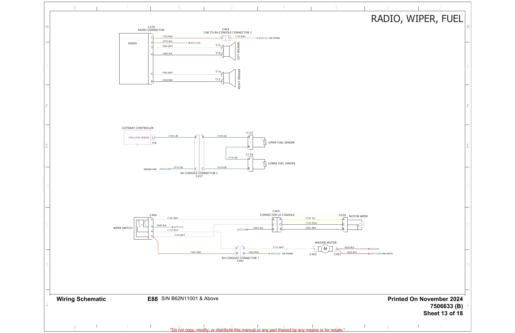
The Engine Control Unit description explains injection quantity, timing, and pressure control from sensor inputs. Camshaft and crankshaft position-sensor R&I, auto-idle pressure-switch service, travel-motion-alarm checks, and multi-sheet wiring schematics labeled E88 S/N B62N11001 & Above (example sheets include Radio/Wiper/Fuel and HVAC) give a path from a stored code to a connector.
Cab service in the safety section plus section 80 covers the ROPS / TOPS / FOPS structure (ISO 3471 / ISO 12117-2 / ISO 10262 Level I), door and window latches including the front window raise-and-latch sequence, emergency exits through the front or right window, windshield washer reservoir, HVAC louvers, recirculation and fresh-air filters, R-134a charge of 1,18 kg (2.6 lb), compressor belt, reclaim/charge with a recovery unit, and Auto HVAC ATM flash codes.
2.4 L V2 Stage 5 Engine and DPF
Engine service is a full teardown path, not a filter-only chapter. After the description and sensor map, the book lists metric and component torque values, a cause-coded troubleshooting chart (will not start, no power, low oil pressure, knocking, running rough, and related faults), then engine R&I with designated lift brackets. Shop tests include compression through the glow-plug adapter (MEL10630 kit plus 7313843 adapter), in-line injector signal, and oil pressure at the turbocharger inlet (minimum 10 psi within four seconds of start; high-idle gauge pressure 300 kPa / 3,0 bar / 44.0 psi).
The DPF chapter defines passive, automatic, forced, and forced-parked regeneration, icon behavior, and the gates for a forced cycle (no active DPF codes, coolant above 40°C / 104°F, soot load 75–120 percent, more than 25 percent fuel). Fuel-system R&I runs from filter housing and lift pump through the transfer / high-pressure pump, fuel recirculation valve, rail, injectors, and the requirement to write each injector ID code into the ECU with the Bobcat V2 Engine Analyzer, then run ten minutes at full throttle for learning.
Bottom-end and top-end work includes piston and rod R&I, cylinder-block bore 89.990–90.010 mm (3.5429–3.5437 in), crankshaft and connecting-rod inspection with component-class tables, camshaft and bushing, gear-case timing and backlash, turbocharger oil feed and drain, flywheel and ring gear (flywheel bolts 67,8 N·m / 50 ft-lb plus 45°), and EGR. Head-bolt tightening is initial 39 N·m (29 ft-lb) plus 90° + 90° + 90°. Coolant choices are purple 53% propylene glycol / 47% water or red 50% ethylene glycol / 50% water; the thermostat is fully open at 97°C (207°F); radiator cap is 110 kPa (1,1 bar / 16 psi).
Capacities, Performance, and Shop Data
Section 90 collects the numbers used throughout the procedures. Operating weight for a cab with HVAC, short arm, rubber tracks, counterweight, standard bucket, and 75 kg (165 lb) operator is 8994 kg (19827 lb), with adders for steel tracks, add-on counterweight, long arm, and articulated boom. Travel speed is 2,5 / 4,4 km/h (1.6 / 2.7 mph). Digging forces per ISO 6015 are listed for long arm, short arm, articulated boom retracted and extended, and bucket. Fuel tank 116 L (30.6 U.S. gal), hydraulic reservoir 21,4 L (5.65 U.S. gal), hydraulic system at sight-glass center 81,4 L (21.5 U.S. gal), cooling system 10,4 L (2.75 U.S. gal), engine oil and filter 9,8 L (10.35 qt). Track width is 450 mm (17.7 in) for rubber, steel, and segmented options; crawler width is 2200 mm (86.6 in); slew speed is 9,0 rpm. Lift-capacity charts cover long arm, standard arm, add-on counterweight combinations, and articulated boom. Service-tool lists name the Remote Start kit, hydraulic tester MEL1744, engine analyzer, compression and seal tools, and HVAC service equipment used in the procedures.
Get the Manual and Get Back on the Job
With the Bobcat E88 Compact Excavator Service Manual S/N B62N11001 & Above 2025 on the bench you can lift and block the machine correctly, follow the service schedule, test and rebuild work-group cylinders, set pump margin and torque-limiter flow, service rubber or steel tracks, trace a charging or display fault, regenerate or replace the DPF, measure a cylinder bore, code new injectors, charge the R-134a system, and check every torque and capacity against the published tables. Using the printed pressures, idle speeds, and tightening sequences avoids guesswork that damages a Stage 5 fuel system, a load-sensing pump, or a ROPS cab. After payment you receive the PDF immediately — no shipping wait — so you can open it on a shop computer, tablet, or phone and print the pages you need for the current repair.
Reviews
There are no reviews yet.