★ TRUSTED BY 321,897+ PROFESSIONALS WORLDWIDE
🏢
Trusted Business
Verified & Licensed
🛡️
Virus Free Files
100% Safe Downloads
🔒
Secure Payment
SSL Protected
Instant Delivery
Available Immediately
Sale!

Bobcat S250, S300 Turbo Skid-Steer Loader Service Manual (S/N 526011001+, 526111001+, 525811001+, 525911001+) – 6902711

Original price was: $39.95.Current price is: $24.95.

Factory service manual for Bobcat S250 and S300 Turbo Skid-Steer Loaders (including High Flow). Covers machine serial numbers 526011001 & Above, 526111001 & Above, 525811001 & Above, and 525911001 & Above. Contains 1,076 pages of complete shop repair instructions, full hydraulic schematics, electrical troubleshooting, drive systems, BICS diagnostics, engine overhaul, and detailed technical specifications in PDF format.

Instant PDF Download
Available immediately
💾
Save to Your Device
Download & keep forever
🛡️
Antivirus Scanned
100% virus-free
🌍
Trusted Worldwide
175,000+ customers

Description

The Bobcat S250, S300 Turbo Skid-Steer Loader Service Manual (S/N 526011001+, 526111001+, 525811001+, 525911001+) – 6902711 is the definitive workshop reference designed for professional service mechanics, heavy equipment technicians, and owner-operators demanding factory-accurate repair procedures. Spanning 1,076 comprehensive pages, this official publication provides complete step-by-step disassembly, inspection, reconditioning, assembly, and testing instructions across all major systems of the Bobcat S250 Turbo and Bobcat S300 Turbo loader platforms, including standard flow and high-flow configurations.

File Details

  • Document Type: Factory Service Manual
  • Manufacturer: Bobcat Company
  • Machine Models Covered: Bobcat S250 Turbo and Bobcat S300 Turbo Skid-Steer Loaders (Includes High Flow)
  • Applicable Serial Numbers: S250 (S/N 526011001 & Above, S/N 526111001 & Above); S300 (S/N 525811001 & Above, S/N 525911001 & Above)
  • Publication / Part Number: 6902711 (6-12) Revised June 2012
  • Page Count: 1,076 pages
  • Language: English
  • Document Format: High-Resolution Digital PDF

Comprehensive Systems & Technical Coverage

Every mechanical, hydraulic, hydrostatic, and electrical circuit is covered with clear exploded views, precise torque values, and diagnostic flowcharts. Whether tackling basic shop maintenance or executing a ground-up rebuild, this Bobcat S250 S300 service manual equips technicians with the authoritative technical data directly published by the manufacturer.

Key areas covered include:

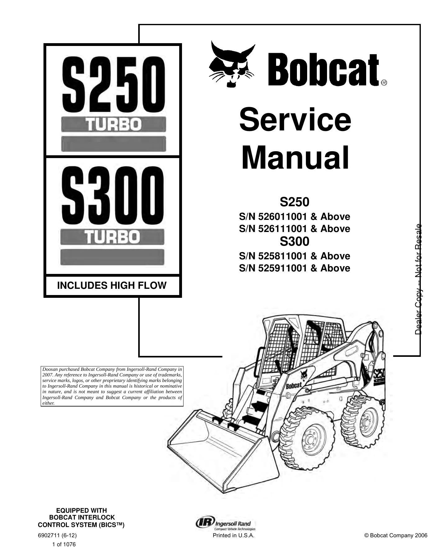
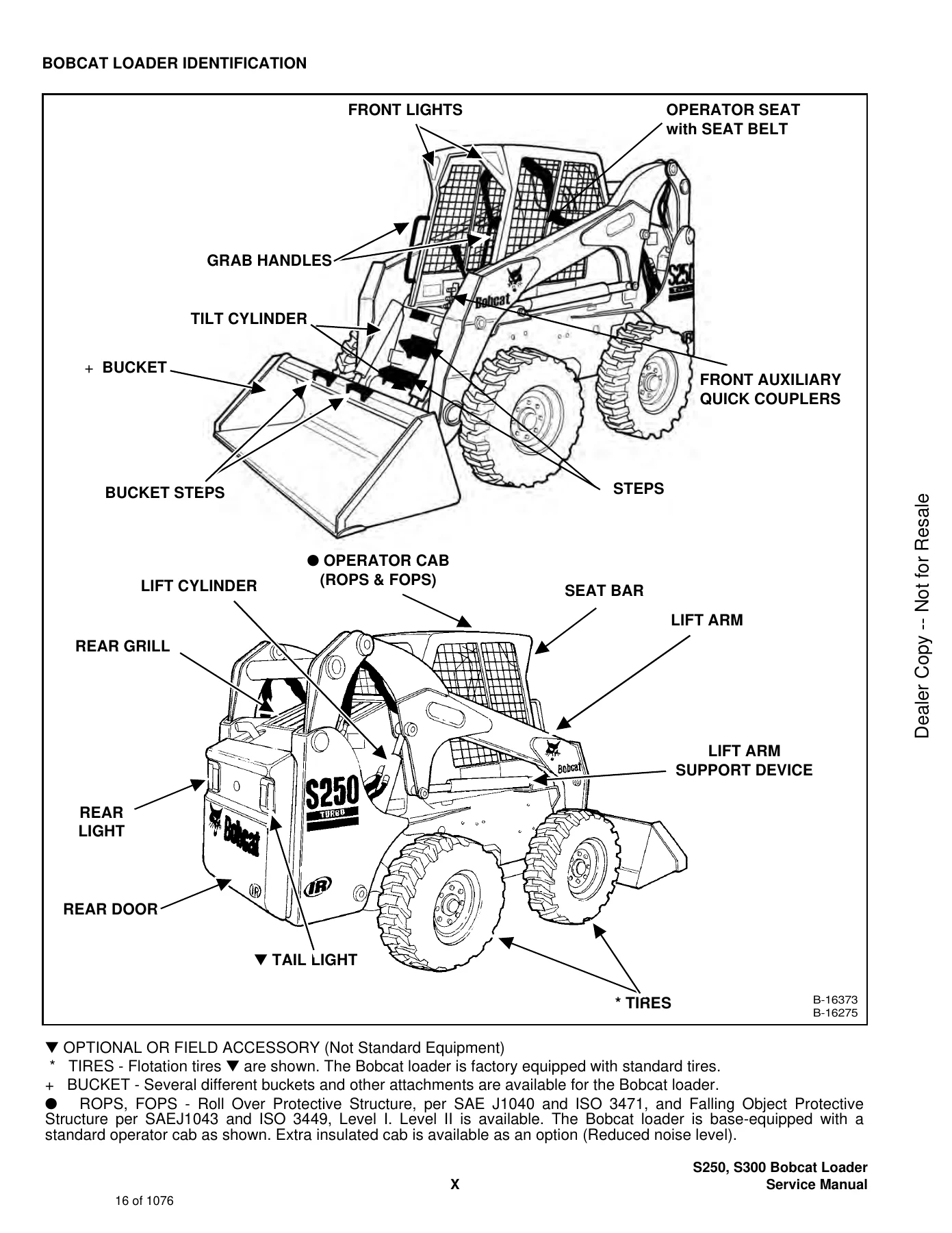
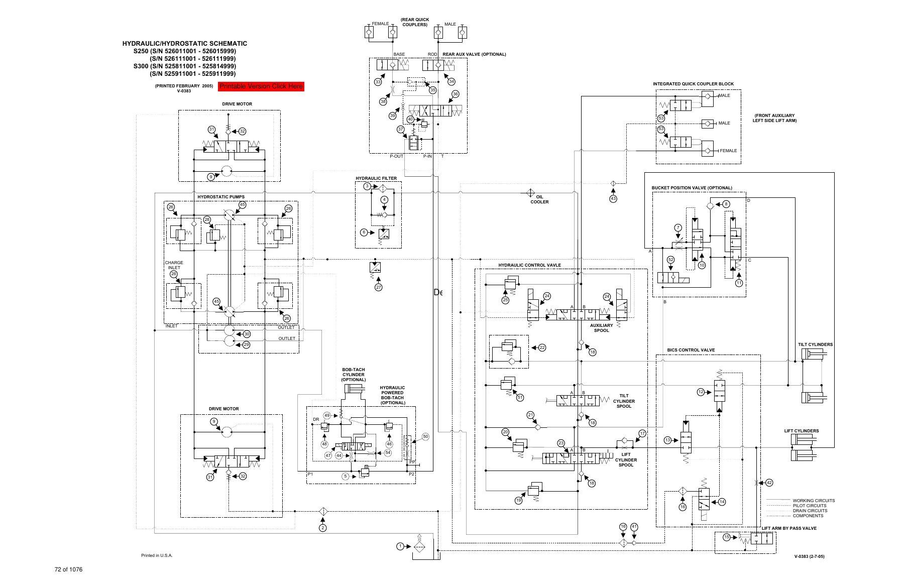
IMAGES PREVIEW

Bobcat S250, S300 Turbo Skid-Steer Loader Service Manual (S/N 526011001+, 526111001+, 525811001+, 525911001+) - 6902711 — PDF page 1 preview
Bobcat S250, S300 Turbo Skid-Steer Loader Service Manual (S/N 526011001+, 526111001+, 525811001+, 525911001+) - 6902711 — PDF page 16 preview
Bobcat S250, S300 Turbo Skid-Steer Loader Service Manual (S/N 526011001+, 526111001+, 525811001+, 525911001+) - 6902711 — PDF page 72 preview

  • Hydraulic Systems & Controls: Complete coverage for standard foot control, Advanced Control System (ACS) selectable hand/foot controls, and Selectable Joystick Control (SJC) systems. Details both 1-piece and 2-piece casting hydraulic control valves, main relief valve calibration (3250–3350 PSI), port relief valves (up to 4000 PSI), anti-cavitation valves, tilt and lift spool servicing, load check poppets, and bucket positioning valves.
  • Hydrostatic Drive System: Complete diagnostic testing and teardown procedures for variable displacement bi-directional hydrostatic pumps, high-pressure relief and replenishing valves (5000–5220 PSI), fixed-capacity drive motors, two-speed motors and shifting valves, charge pressure verification (400–460 PSI), oil cooler plumbing, drive belt tensioning, and hydrostatic motor carrier overhauls.
  • Cylinder Rebuilding & Pin Servicing: Dedicated teardown and rebuild procedures for lift cylinders, tilt cylinders, and power Bob-Tach cylinders. Includes specialized disassembly using spanner tooling, rod seal collapsing techniques, head gland packing, and critical piston retaining nut torques—including 600 ft-lbs (814 Nm) for lift cylinder nuts and specific rotational tightening procedures for tilt cylinders.
  • Bobcat Interlock Control System (BICS) & Safety: Complete logic schematics, valve manifold overhaul, solenoid testing (5–8 ohms standard, 7–10 ohms bypass/relief), seat bar sensor calibration, lift arm bypass control servicing, and remote start diagnostic procedures utilizing the MEL1563 service tool kit.
  • Final Drive & Mainframe: Axle tube bearing service, sprocket and drive chain inspection, chaincase oil drainage and filling, front chaincase cover removal, parking brake engagement, two-speed brake rebuilds, Bob-Tach mechanical linkage inspection, and ROPS/FOPS tilt cab lifting/lowering safety measures.
  • Electrical System & Electronic Diagnostics: Complete harness routing, alternator and starter diagnostics, instrument cluster pinouts, electronic security system integration, controller programming, sensor calibrations, and alphabetical listings of machine service diagnostic trouble codes.
  • Engine Service & Support Systems: Fuel system bleeding via hand priming bulb, air cleaner maintenance with restriction code monitoring, cooling system maintenance utilizing 47/53 propylene glycol mixture, fan drive gearbox lubrication, and full mechanical engine removal, reconditioning, and overhaul instructions.
  • Heating, Ventilation & Air Conditioning (HVAC): Refrigerant recovery, evacuation, and charging protocols, compressor clutch checks, condenser and evaporator cleaning, heater core plumbing, thermostat switches, and air conditioning diagnostic symptom tables.

Complete PDF Bookmark Tree

Complete Bookmarks

The complete bookmarks in the “Bobcat S250, S300 Turbo Skid-Steer Loader Service Manual (S/N 526011001+, 526111001+, 525811001+, 525911001+) – 6902711” are as follows:

MAINTENANCE SAFETYp. 3
ALPHABETICAL INDEXp. 5
CONTENTSp. 7
FOREWORDp. 9
SAFETY INSTRUCTIONSp. 11
Fire Preventionp. 13
SERIAL NUMBER LOCATIONp. 15
Loader Serial Numberp. 15
Engine Serial Numberp. 15
DELIVERY REPORTp. 15
BOBCAT LOADER IDENTIFICATIONp. 16
SAFETY AND MAINTENANCEp. 17
LIFTING AND BLOCKING THE LOADERp. 19
Procedurep. 19
LIFT ARM SUPPORT DEVICEp. 21
Installing The Lift Arm Support Devicep. 21
Removing The Lift Arm Support Devicep. 22
OPERATOR CABp. 23
Descriptionp. 23
Raising The Operator Cabp. 23
Lowering The Operator Cabp. 24
Emergency Exitp. 24
TRANSPORTING THE BOBCAT LOADERp. 27
Procedurep. 27
TOWING THE LOADERp. 29
Procedurep. 29
REMOTE STARTp. 31
Procedure For Loader W/O Attachments Control Harnessp. 31
Procedure For Loader With Attachments Control Harnessp. 32
Procedurep. 33
SERVICE SCHEDULEp. 35
Chartp. 35
AIR CLEANER SERVICEp. 37
Replacing Filter Elementp. 37
ENGINE COOLING SYSTEMp. 39
Cleaning Cooling Systemp. 39
Checking The Coolant Levelp. 41
Adding The Coolantp. 42
FUEL SYSTEMp. 43
Fuel Specificationsp. 43
Filling The Fuel Tankp. 43
Fuel Filterp. 43
Removing Air From The Fuel Systemp. 44
ENGINE LUBRICATION SYSTEMp. 45
Checking Engine Oilp. 45
Oil Chartp. 45
Replacing Oil And Filterp. 45
HYDRAULIC/HYDROSTATIC SYSTEMp. 47
Checking And Adding Fluidp. 47
Hydraulic Fluid Chartp. 47
Hydraulic/Hydrostatic Filter Replacementp. 48
Replacing Hydraulic Fluid And Case Drain Filtersp. 49
FINAL DRIVE TRANSMISSION (CHAINCASE)p. 51
Checking And Adding Oilp. 51
Removing The Oilp. 51
FAN GEARBOXp. 53
Checking And Adding Oilp. 53
BOB-TACHp. 55
Inspection And Maintenancep. 55
POWER BOB-TACHp. 57
Inspection And Maintenancep. 57
LUBRICATING THE LOADERp. 59
Procedurep. 59
Pivot Pinsp. 61
TIRE MAINTENANCEp. 63
Wheel Nutsp. 63
Tire Rotationp. 63
Tire Mountingp. 63
HYDRAULIC SYSTEMp. 65
HYDRAULIC/HYDROSTATIC SCHEMATICSp. 71
HYDRAULIC SYSTEM INFORMATIONp. 103
Troubleshootingp. 107
Tightening Procedurep. 108
CYLINDER (LIFT)p. 109
Checkingp. 109
Removal And Installationp. 109
Parts Identificationp. 111
Disassemblyp. 112
Assemblyp. 113
CYLINDER (TILT)p. 117
Checkingp. 117
Removal And Installationp. 117
Base Pin Removal And Installationp. 119
Parts Identificationp. 120
Disassemblyp. 121
Assemblyp. 122
CYLINDER (POWER BOB-TACH)p. 125
Checkingp. 125
Removal And Installationp. 126
Parts Identificationp. 127
Disassemblyp. 128
Assemblyp. 129
MAIN RELIEF VALVEp. 133
Checking Main Reliefp. 133
Adjustmentp. 135
Removal And Installationp. 136
HYDRAULIC CONTROL VALVE (2 PIECE CASTING) (FOOT CONTROL)p. 137
Identificationp. 137
Removal And Installationp. 137
BICS™ Valve, Removal And Installationp. 141
BICS™ Valve, Lift Arm By-Pass Orifice Removal And Installationp. 143
BICS™ Valve, Check Valve Removal And Installationp. 144
Backslide, Lock Valve Removal And Installationp. 145
BICS™ Valve, Solenoid Removal And Installationp. 146
BICS™ Valve, Solenoid Testingp. 147
Identification Chartp. 148
Load Check Valvep. 149
Main Relief Valvep. 150
Port Relief Valve, Tilt Spoolp. 150
Port Relief Valve, Lift Spoolp. 151
Anti-Cavitation Valve/Port Relief Valve, Tilt Spoolp. 151
Anti-Cavitation Valve, Lift Spoolp. 152
Rubber Bootp. 152
Lift And Tilt Lock Blockp. 153
Lift Spool And Detent Removalp. 154
Lift Spool And Detent Disassemblyp. 156
Lift Spool And Detent Assemblyp. 159
Lift Spool And Detent Installationp. 163
Tilt Spool Removal And Installationp. 164
Tilt Spool Disassembly And Assemblyp. 165
Auxiliary Spool Removal And Installationp. 166
Auxiliary Plug Removal And Installationp. 168
Auxiliary Electric Solenoid Disassemblyp. 169
Port-Auxiliary Section Removal And Installationp. 170
Cleaning And Inspectionp. 170
HYDRAULIC CONTROL VALVE (2 PIECE CASTING) (ADVANCED CONTROL SYSTEM) (ACS)p. 171
Identificationp. 171
Actuator Removal And Installation (In Loader)p. 172
Actuator Removal And Installation (Out Of Loader)p. 175
Removal And Installationp. 177
BICS™ Valve, Removal And Installationp. 181
BICS™ Valve, Lift Arm By-Pass Orifice Disassembly And Assemblyp. 184
BICS™ Valve, Check Valve Disassembly And Assemblyp. 185
BICS™ Valve, Lock Valve Disassembly And Assemblyp. 186
BICS™ Valve, Solenoid Disassembly And Assemblyp. 187
BICS™ Valve, Solenoid Testingp. 188
Identification Chartp. 189
Lift Base End Restrictorp. 190
Load Check Valvep. 191
Main Relief Valvep. 192
Port Relief Valvep. 194
Anti-Cavitation Valve/Port Relief Valvep. 195
Anti-Cavitation Valvep. 196
Lift Spool Removalp. 197
Lift Spool Removal And Installationp. 198
Lift and Tilt Spool Disassembly And Assemblyp. 199
Auxiliary Spool Removal And Installationp. 200
Auxiliary Electric Solenoid Disassemblyp. 201
Port-Auxiliary Section Disassemblyp. 202
Cleaning And Inspectionp. 202
HYDRAULIC CONTROL VALVE (2 PIECE CASTING) (selectable joystick control) (sjc)p. 203
Identificationp. 203
Actuator Removal And Installation (In Loader)p. 204
Actuator Removal And Installation (Out Of Loader)p. 207
Removal And Installationp. 209
BICS™ Valve, Removal And Installationp. 213
BICS™ Valve, Lift Arm By-Pass Orifice Disassembly And Assemblyp. 216
BICS™ Valve, Check Valve Disassembly And Assemblyp. 217
BICS™ Valve, Lock Valve Disassembly And Assemblyp. 218
BICS™ Valve, Solenoid Disassembly And Assemblyp. 219
BICS™ Valve, Solenoid Testingp. 220
Identification Chartp. 221
Lift Base End Restrictorp. 222
Load Check Valvep. 222
Main Relief Valvep. 223
Port Relief Valvep. 224
Anti-Cavitation Valve/Port Relief Valvep. 225
Anti-Cavitation Valvep. 226
Lift Spool Removalp. 227
Lift Spool Removal And Installationp. 228
Lift and Tilt Spool Disassembly And Assemblyp. 229
Auxiliary Spool Removal And Installationp. 230
Auxiliary Electric Solenoid Disassemblyp. 231
Port-Auxiliary Section Disassemblyp. 232
Cleaning And Inspectionp. 232
HYDRAULIC CONTROL VALVE (1 PIECE CASTING) (FOOT CONTROL)p. 233
Identificationp. 233
Removal And Installationp. 233
Identification Chartp. 238
BICS™ Valve, Lift Load Check Valve Removal And Installationp. 239
Load Check Valve Removal And Installation (Tilt & Auxiliary)p. 240
Anti-Cavitation Valve (Lift, Rod End)p. 240
Port Relief/Anti-Cavitation Valve (Lift, Base End)p. 241
Port Relief/Anti-Cavitation Valve (Tilt, Base End)p. 242
Port Relief/Anti-Cavitation Valve (Tilt, Rod End)p. 242
Port Relief Valvep. 243
Plug Removalp. 244
Rubber Boot Removal and Installationp. 245
End Cap/Spool Lock Block Removal and Installationp. 246
Lift Spool and Detent Removal and Installationp. 247
Auxiliary Spool Removal And Installationp. 259
Auxiliary Solenoid Disassembly and Assemblyp. 261
BICS™ Valve Solenoid Disassembly And Assemblyp. 262
BICS™ Valve, Lock Valve Removal And Installationp. 263
BICS™ Valve, Lift Arm By-Pass Orifice Disassembly And Assemblyp. 265
Main Relief Valvep. 265
BICS™ Valve, Check Valve Removal and Installationp. 266
HYDRAULIC CONTROL VALVE (1 PIECE CASTING) (ADVANCED CONTROL SYSTEM) (ACS)p. 267
Identificationp. 267
Removal And Installationp. 268
Actuator Removal And Installation (In Loader)p. 272
Identification Chartp. 277
BICS™ Valve, Lift Load Check Valve Removal And Installationp. 278
Load Check Valve Removal And Installation (Tilt & Auxiliary)p. 279
Anti-Cavitation Valve (Lift, Rod End)p. 279
Port Relief/Anti-Cavitation Valve (Lift, Base End)p. 280
Port Relief/Anti-Cavitation Valve (Tilt, Base End)p. 281
Port Relief/Anti-Cavitation Valve (Tilt, Rod End)p. 281
Port Relief Valvep. 282
Plug Removalp. 283
End Cap Block Removal And Installationp. 284
Lift Spool Removal And Installationp. 285
Auxiliary Spool Removal And Installationp. 291
Auxiliary Solenoid Disassembly And Assemblyp. 293
BICS™ Valve Solenoid Disassembly And Assemblyp. 294
BICS™ Valve, Lock Valve Removal And Installationp. 295
BICS™ Valve, Lift Arm By-Pass Orifice Disassembly And Assemblyp. 297
Main Relief Valvep. 297
BICS™ Valve, Check Valve Removal And Installationp. 298
HYDRAULIC CONTROL VALVE (1 PIECE CASTING) (SELECTABLE JOYSTICK CONTROL) (SJC)p. 299
Identificationp. 299
Removal And Installationp. 300
Actuator Removal And Installation (In Loader)p. 304
Actuator Removal And Installation (Out of Loader)p. 306
Identification Chartp. 309
BICS™ Valve, Lift Load Check Valve Removal And Installationp. 310
Load Check Valve Removal And Installation (Tilt & Auxiliary)p. 311
Anti-Cavitation Valve (Lift, Rod End)p. 311
Port Relief/Anti-Cavitation Valve (Lift, Base End)p. 312
Port Relief/Anti-Cavitation Valve (Tilt, Base End)p. 313
Port Relief/Anti-Cavitation Valve (Tilt, Rod End)p. 313
Port Relief Valvep. 314
Plug Removalp. 315
End Cap Block Removal And Installationp. 316
Lift Spool Removal And Installationp. 317
Auxiliary Spool Removal And Installationp. 323
Auxiliary Solenoid Disassembly And Assemblyp. 325
BICS™ Valve Solenoid Disassembly And Assemblyp. 326
BICS™ Valve, Lock Valve Removal And Installationp. 327
BICS™ Valve, Lift Arm By-Pass Orifice Disassembly And Assemblyp. 329
Main Relief Valvep. 329
BICS™ Valve, Check Valve Removal And Installationp. 330
LIFT ARM BY-PASS CONTROL VALVEp. 331
Inspectingp. 331
Additional Inspection For Loaders W/Advanced Hand Controlsp. 331
Removal And Installationp. 331
Disassembly And Assemblyp. 332
HYDRAULIC PUMPp. 333
Check The Output Of The Hydraulic Pumpp. 333
Removal And Installationp. 334
Identificationp. 336
Disassembly And Assemblyp. 337
HYDRAULIC PUMP (CHARGE)p. 345
Check The Output Of The Hydraulic Pumpp. 345
Removal And Installationp. 348
Disassembly And Assemblyp. 348
HYDRAULIC PUMP (HIGH FLOW)p. 349
Hydraulic Pump Test (30 GPM)p. 349
Hydraulic Pump Test (40 GPM)p. 350
Inline Hydraulic Pump Test (Standard)p. 351
Inline Hydraulic Pump Test (High Flow) (30 GPM And 40 GPM)p. 353
High Flow Relief Adjustment Procedure (30 GPM And 40 GPM)p. 355
High Flow Relief Valve Removal and Installation (30 GPM And 40 GPM)p. 357
Removal And Installation (30 GPM And 40 GPM)p. 358
Identification (30 GPM) (S/N 526016699 & Below) (S/N 525815599 & Below)p. 360
Identification (40 GPM) (S/N 526016700 & Above) (S/N 525815600 & Above)p. 361
Disassembly And Assembly (30 GPM And 40 GPM)p. 362
HYDRAULIC PUMP (SELECTABLE JOYSTICK CONTROL) (SJC)p. 375
Check The Output Of The Hydraulic Pumpp. 375
Removal And Installationp. 376
Identificationp. 378
Disassembly And Assemblyp. 379
HYDRAULIC PUMP (HIGH FLOW) (SELECTABLE JOYSTICK CONTROL) (SJC)p. 385
Hydraulic Pump Test (30 GPM)p. 385
Hydraulic Pump Test (40 GPM)p. 386
Inline Hydraulic Pump Test (Standard)p. 387
Inline Hydraulic Pump Test (High Flow) (30 GPM And 40 GPM)p. 389
High Flow Relief Adjustment Procedure (30 GPM And 40 GPM)p. 391
High Flow Relief Valve Removal And Installation (30 GPM And 40 GPM)p. 393
Removal And Installation (30 GPM And 40 GPM)p. 395
Identification (30 GPM) (S/N 525815599 & Below) (S/N 526016699 & Below)p. 397
Identification (40 GPM) (S/N 525815600 & Above) (S/N 526016700 & Above)p. 398
Disassembly And Assembly (30 GPM And 40 GPM)p. 399
HYDRAULIC/HYDROSTATIC FILTERp. 409
Housing Removal And Installationp. 409
Mount Removal And Installationp. 410
HYDRAULIC FLUID RESERVOIRp. 411
Fluid Removalp. 411
Removal And Installationp. 411
Hydraulic Fluid Screenp. 414
BUCKET POSITION VALVEp. 417
Solenoid Removal And Installationp. 417
Solenoid Testingp. 417
Removal And Installationp. 418
Disassembly And Assemblyp. 418
REAR AUXILIARY DIVERTERp. 421
Removal and Installationp. 421
Disassembly And Assemblyp. 423
Solenoid Testingp. 428
Inspectionp. 428
POWER BOB-TACH BLOCKp. 429
Removal And Installationp. 429
Disassembly And Assemblyp. 430
FRONT AUXILIARY HYDRAULIC COUPLER BLOCKp. 435
Removal and Installationp. 435
Disassembly And Assemblyp. 435
HYDROSTATIC SYSTEMp. 437
HYDROSTATIC SYSTEM INFORMATIONp. 439
Troubleshootingp. 439
Replenishing Valve Functionp. 440
HYDROSTATIC MOTORp. 441
Removal And Installationp. 441
Parts Identificationp. 442
Disassemblyp. 443
Inspectionp. 445
Assemblyp. 446
HYDROSTATIC MOTOR (TWO-SPEED)p. 451
Removal And Installationp. 451
Parts Identificationp. 453
Disassemblyp. 455
Inspectionp. 462
Assemblyp. 463
HYDROSTATIC MOTOR CARRIERp. 471
Removal and Installationp. 471
Parts Identificationp. 473
Disassemblyp. 474
Assemblyp. 475
HYDROSTATIC MOTOR CARRIER (SELECTABLE JOYSTICK CONTROL) (SJC)p. 477
Removal And Installationp. 477
Parts Identificationp. 478
Disassemblyp. 479
Assemblyp. 481
CHARGE PRESSUREp. 485
Testingp. 485
Removal And Installationp. 487
Setting Charge Pressurep. 488
HYDROSTATIC PUMPp. 489
Removal And Installationp. 489
Replenishing/High Pressure Relief Valvep. 491
Parts Identification (Right Half)p. 492
Parts Identification (Left Half)p. 494
Hydraulic Pump Removal And Installationp. 496
Pump Separationp. 496
Disassemblyp. 497
Assemblyp. 503
HYDROSTATIC PUMP (SELECTABLE JOYSTICK CONTROL)p. 511
Pump Controller Removal And Installationp. 511
Hydrostatic Pump Calibrationp. 514
Removal And Installationp. 519
Parts Identification (Right Half)p. 521
Parts Identification (Left Half)p. 523
System Check Relief Valves (High Pressure Relief, Charge Check & By-Pass Valve)p. 525
Charge Relief Valvep. 526
Pump Separationp. 528
Shaft Seal And Shaft Replacementp. 529
Shaft Seal And Shaft Installationp. 531
Charge Pump Removalp. 533
Charge Pump Inspectionp. 535
Charge Pump Installationp. 536
Disassemblyp. 538
Inspectionp. 545
Assemblyp. 549
Pump Neutral Adjustmentp. 558
Pump Controller Neutral Adjustmentp. 561
DRIVE BELTp. 565
Shield Removal And Installationp. 565
Adjustmentp. 565
Replacementp. 565
Tensioner Pulley Removal And Installationp. 566
Tensioner Pulley Tension Springp. 568
OIL COOLER (SEAL TO CONNECT) (STC)p. 569
Hydraulic Oil Cooler Removal And Installationp. 569
DRIVE SYSTEMp. 571
BRAKEp. 573
Disc Removal And Installationp. 573
BRAKE (TWO-SPEED)p. 577
Block Removal And Installationp. 577
Block Disassembly And Assemblyp. 578
DRIVE COMPONENTSp. 583
Axle Seal Removal And Installationp. 583
Axle, Sprocket And Bearings Removal And Installationp. 585
Drive Chain Removal And Installationp. 590
CHAINCASEp. 591
Front Chaincase Cover Removal And Installationp. 591
Rear Chaincase Cover Removal And Installationp. 591
MAIN FRAMEp. 593
SEAT BARp. 597
Removal And Installationp. 597
Assembling Componentsp. 598
Compression Spring Disassembly And Assemblyp. 599
OPERATOR CABp. 601
Gas Cylinder Removal And Installationp. 601
Gas Cylinder Bracket Disassembly And Assemblyp. 603
Removal And Installationp. 603
OPERATOR SEATp. 607
Removal And Installationp. 607
Seat Belt Removal And Installationp. 607
OPERATOR SEAT (SUSPENSION)p. 609
Removal And Installationp. 609
Slide Rail Removal And Installationp. 610
Seat Belt Removal and Installationp. 610
Cushion Removal And Installationp. 611
Back Removal And Installationp. 612
Shock Removal And Installationp. 612
3-Point Seat Belt Removal And Installationp. 613
BOB-TACHp. 615
Removal And Installationp. 615
Bob-Tach Lever And Wedgep. 617
POWER BOB-TACHp. 619
Removal And Installationp. 619
Power Bob-Tach Lever And Wedgep. 621
Pivot Pin Bushing And Seal Replacementp. 623
LIFT ARMSp. 625
Stabilizer Bar Removal And Installationp. 625
Link Removal And Installationp. 626
Removal And Installationp. 627
Installation Of Lift Armsp. 629
REAR GRILLp. 631
Removal And Installationp. 631
REAR DOORp. 633
Removal And Installationp. 633
Striker Removal and Installationp. 634
Striker Disassembly and Assemblyp. 634
Door Latch and Catch Adjustmentp. 634
Latch Removal And Installationp. 635
FUEL TANKp. 637
Removal And Installationp. 637
Fuel Level Senderp. 638
CONTROL PEDALSp. 639
Removal And Installationp. 639
Pedal Adjustmentp. 639
CONTROL PEDALS (ACS)p. 641
Foot Sensor Removal And Installationp. 641
Foot Pedal Removal And Installationp. 642
Foot Pedal Linkage Disassembly And Assemblyp. 642
CONTROL PANEL (NON-ADJUSTABLE PINTLES)p. 643
Removal And Installationp. 643
Shock Removal And Installationp. 645
Shaft Removal And Installationp. 645
Shaft Disassembly And Assemblyp. 645
Linkage Removal And Installationp. 647
Linkage Neutral Adjustmentp. 650
CONTROL PANEL (ADJUSTABLE PINTLES)p. 657
Descriptionp. 657
Removal And Installationp. 658
Shock Removal And Installationp. 660
Shaft Removal And Installationp. 660
Shaft Disassembly And Assemblyp. 661
Linkage Removal And Installationp. 662
Pintle Arm Disassembly and Assemblyp. 667
Linkage Neutral Adjustmentp. 668
Linkage Travel Adjustmentp. 672
CONTROL PANEL (SELECTABLE JOYSTICK CONTROL) (SJC)p. 677
Removal And Installationp. 677
CONTROL HANDLEp. 681
Lever Removal And Installationp. 681
Steering Lever Bootp. 681
CONTROL HANDLE (ADVANCED CONTROL SYSTEM) (ACS) SELECTABLE HAND/FOOT CONTROLp. 683
Components Identificationp. 683
Handle Sensor Removal And Installationp. 683
Control Handle Removal And Installationp. 686
Control Handle Disassembly And Assemblyp. 687
Control Lever Removal And Installationp. 688
Control Lever Bootp. 689
CONTROL HANDLE (SELECTABLE JOYSTICK CONTROL) (SJC)p. 691
Joystick Testing (Right & Left)p. 691
Joystick Removal (Right & Left)p. 692
Joystick Boot Removal (Right & Left)p. 693
Lever Assembly Removal (Right & Left)p. 693
INSIDE ACCESS PANELp. 695
Removal And Installation (Left)p. 695
Removal And Installation (Right)p. 695
INSIDE ACCESS PANEL (SELECTABLE JOYSTICK CONTROL) (SJC)p. 697
Panel Removal (Right)p. 697
Panel Removal (Left)p. 700
ELECTRICAL SYSTEM & ANALYSISp. 701
ELECTRICAL SCHEMATICSp. 705
ELECTRICAL SYSTEM INFORMATIONp. 713
Troubleshootingp. 715
Descriptionp. 716
Fuse Locationp. 718
Relay Switch Locationp. 718
Solenoid Testp. 719
BATTERYp. 721
Removal And Installationp. 721
Servicing The Electrical Systemp. 723
Using A Booster Battery (Jump Starting)p. 724
ALTERNATORp. 725
Adjusting The Alternator Beltp. 725
Alternator Identificationp. 725
Charging System Checkp. 726
Alternator Voltage Testp. 727
Low Voltage Testp. 727
High Voltage Testp. 728
Removal And Installationp. 728
Rectifier Continuity (Diode) Testp. 729
Alternator Regulator Testp. 730
Disassemblyp. 731
Stator Continuity Testp. 731
Stator Ground Testp. 731
Rotor Continuity Testp. 732
Rotor Ground Testp. 732
Assemblyp. 732
STARTERp. 733
Checkingp. 733
Removal And Installationp. 734
Parts Identificationp. 735
Disassembly And Assemblyp. 736
Inspection And Repairp. 739
No Load Testp. 742
INSTRUMENT PANELp. 743
Left Panelp. 743
Right Panel (Standard) (With Key Switch)p. 744
Right Panel (Deluxe) (With Keyless Start)p. 745
Right Panel Setup Display Options (Deluxe)p. 747
Deluxe Panel Setupp. 748
Passwords (Deluxe)p. 748
Option And Field Accessory Panels (If Equipped)p. 750
Standard Panel Removal And Installation (Right Side)p. 751
Deluxe Panel Removal And Installation (Right Side)p. 752
Standard & Deluxe Panel Removal And Installation (Left Side)p. 753
Front Accessory Panel Removal And Installationp. 754
LIGHTSp. 755
Front Removal And Installationp. 755
Rear Removal And Installationp. 755
BOBCAT CONTROLLERp. 758
Identification Chartp. 758
Removal And Installationp. 760
CONTROLLER (SELECTABLE JOYSTICK CONTROL) (SJC)p. 761
Removalp. 761
Identification Chartp. 764
SPEED SENSOR (SELECTABLE JOYSTICK CONTROL) (SJC)p. 767
Testingp. 767
Removalp. 768
DIAGNOSTICS SERVICE CODESp. 771
Displayp. 771
Number Codes Listp. 772
BICS™ SYSTEMp. 777
Inspecting The BICS™ Controller (Engine STOPPED – Key ON)p. 777
Inspecting Deactivation Of The Auxiliary Hydraulics System (Engine STOPPED – Key ON)p. 777
Inspecting The Seat Bar Sensor (Engine RUNNING)p. 777
Inspecting The Traction Lock (Engine RUNNING)p. 777
Inspecting The Lift Arm By-Pass Controlp. 778
Additional Inspection For Loaders With Advanced Controls System (ACS) or Selectable Joystick Control (SJC)p. 778
Troubleshootingp. 779
Troubleshooting Guidep. 780
SEAT BAR SENSORp. 781
Troubleshooting Chartp. 781
Testp. 782
Removal And Installationp. 783
BICS™ Circuit Testp. 784
TRACTION LOCKp. 785
Troubleshootingp. 785
Removal And Installation (Single Speed)p. 786
Description Of The Control System (Two Speed)p. 787
Inspecting The Control System (Two Speed)p. 787
ADVANCED CONTROL SYSTEM (ACS)p. 789
Components Identificationp. 789
Troubleshooting Guidep. 791
Controller, Connector And Wire Identificationp. 792
ACS Controller Removal And Installationp. 794
Handle Sensor Connectorp. 795
Switch Handle Removalp. 796
Switch Handle Installationp. 798
Actuators Disassembly And Assemblyp. 801
Handle Lock Solenoid Removal And Installationp. 802
Handle Lock Solenoid Disassembly And Assemblyp. 803
Handle Lock Solenoid Connectorp. 803
Foot Sensor Disassembly And Assemblyp. 804
Foot Sensor Connectorp. 805
Foot Lock Solenoid Removal And Installationp. 806
Foot Lock Solenoid Connectorp. 807
ELECTRICAL/HYDRAULIC CONTROLS REFERENCEp. 809
Controls Identification Chartp. 809
ELECTRICAL/HYDRAULIC CONTROLS REFERENCE (selectable JOYstick control) (sjc)p. 811
Controls Identification Chartp. 811
SERVICE PC (LAPTOP COMPUTER)p. 815
Connecting The Service PC To Remote Start Toolp. 815
CALIBRATIONp. 817
Lift and Tilt Calibration Procedure (Selectable Joystick Control) (SJC)p. 817
Hydrostatic Pump Calibration (Selectable Joystick Control) (SJC)p. 819
Calibration Procedure (Advanced Control System) (ACS)p. 824
FLYWHEEL RPM SENSORp. 827
Adjustmentp. 827
ENGINE SERVICEp. 829
TROUBLESHOOTINGp. 833
Chartp. 833
ENGINE SPEED CONTROLp. 835
Removal And Installationp. 835
Speed Control Cablep. 836
ENGINE SPEED CONTROL (SELECTABLE JOYSTICK CONTROL) (SJC)p. 839
Removalp. 839
Disassemblyp. 841
Speed Control Cablep. 842
MUFFLERp. 843
Removal And Installationp. 843
AIR CLEANERp. 845
Housing Removal And Installationp. 845
RADIATORp. 847
Removal And Installationp. 847
Mount Removal (Early Loaders)p. 849
Mount Removal (Later Loaders)p. 849
COOLING FANp. 851
Drive Tension Pulley Removal And Installationp. 851
Gearbox/Blower Housing Removal And Installationp. 852
Blower Removal And Installationp. 853
Gearbox Parts Identificationp. 855
Gearbox Disassemblyp. 856
Gearbox Assemblyp. 861
Gearbox, Checking Backlashp. 866
ENGINEp. 869
Removal And Installationp. 869
Mount Replacementp. 876
Removal And Installation Toolsp. 877
FLYWHEEL AND HOUSINGp. 879
Flywheel Removal And Installationp. 879
Ring Gear Removal And Installationp. 879
Flywheel Housing Removal And Installationp. 879
RECONDITIONING THE ENGINEp. 881
Engine Tools Identification Chartp. 881
Compression Pressurep. 886
Cylinder Head Clearancep. 886
Valve Cover, Injector Nozzle And Seal Removal And Installationp. 887
Checking Nozzle Injection Pressurep. 889
Nozzle Spraying Conditionp. 890
Valve Seat Tightnessp. 890
Rocker Arm And Push Rod Disassembly And Assemblyp. 891
Valve Clearancep. 891
Cylinder Head And Tappet Disassembly And Assemblyp. 892
Selecting Cylinder Head Gasket Disassembly And Assemblyp. 893
Valve Disassembly And Assemblyp. 895
Engine Timing (TDC)p. 895
Injection Pump Housing Removalp. 896
Injection Pump Governor Housing Removal And Installationp. 899
Injection Pump Governor Fork Lever Removal And Installationp. 901
Injection Pump Governor Lever Removal And Installationp. 901
Injection Pump Stop Lever Removal And Installationp. 902
Injection Pump Fuel Camshaft And Governor Weight Removal And Installationp. 902
Injection Pump Removal and Installationp. 904
Injection Pump Housing Installationp. 911
Injection Pump Timingp. 914
Fan Drive Pulley Disassembly And Assemblyp. 916
Water Pump Disassembly And Assemblyp. 917
Oil Cooler And Water Pipe Disassembly And Assemblyp. 917
Gearcase Cover Disassembly And Assemblyp. 918
Idle Gear And Camshaft Disassembly And Assemblyp. 919
Oil Pan And Oil Strainer Disassembly And Assemblyp. 919
Connecting Rod Cap Disassembly And Assemblyp. 920
Piston Disassembly And Assemblyp. 920
Piston Ring And Connecting Rod Disassembly And Assemblyp. 921
Flywheel And Crankshaft Disassembly And Assemblyp. 922
Bearing Case Cover Disassembly And Assemblyp. 923
Flywheel Housing Disassembly And Assemblyp. 924
Crankcase No. 2 Disassembly And Assemblyp. 924
Crankcase No. 1 And No. 2 Disassembly And Assemblyp. 925
Crankshaft Disassembly And Assemblyp. 925
Cylinder Head Surface Flatnessp. 926
Cylinder Head Flawp. 927
Valve Recessingp. 927
Valve Lappingp. 928
Clearance Between Valve Stem And Valve Guidep. 928
Replacing Valve Guidep. 929
Correcting Valve And Valve Seatp. 929
Free Length And Tilt Of Valve Springp. 930
Valve Spring Setting Loadp. 930
Oil Clearance Between Rocker Arm Shaft And Bearingp. 931
Oil Clearance Between Tappet And Tappet Guide Borep. 931
Timing Gear Backlashp. 932
Idler Gear Side Clearancep. 932
Camshaft Side Clearancep. 933
Camshaft Alignmentp. 933
Cam Heightp. 933
Oil Clearance Between Idler Gear Shaft And Idler Gearing Bushingp. 934
Replacing Idler Gear Bushingp. 935
Piston Pin Bore I.D.p. 936
Oil Clearance Between Piston Pin And Small End Bushingp. 936
Replacing Small End Bushingp. 937
Clearance Between Piston Ring And Groovep. 937
Piston Ring Gapp. 938
Connecting Rod Alignmentp. 938
Crankshaft Side Clearancep. 939
Crankshaft Alignmentp. 940
Oil Clearance Between Crankpin And Crankpin Bearingp. 940
Oil Clearance Between Crankshaft Journal And Crankshaft Bearingp. 942
Replacing Crankshaft Sleevep. 943
Cylinder Bore I.D.p. 943
Correcting Cylinder (Oversize +0.5 mm)p. 944
Engine Oil Pressurep. 944
Rotor Lobe Clearancep. 945
Clearance Between Outer Rotor And Pump Bodyp. 945
Clearance Between Rotor And Coverp. 945
Relief Valvep. 946
Thermostat Valve Opening Temperaturep. 946
Radiator Water Leakagep. 946
Radiator Cap Air Leakagep. 947
Thermostat Assemblyp. 947
Intake Air Heaterp. 948
Air Cleaner, Intake Pipe, Inlet Pipe And Mufflerp. 949
Oil Pipep. 949
Turbochargerp. 950
HEATING, VENTILATION, AIR CONDITIONINGp. 951
AIR CONDITIONING SYSTEM FLOWp. 954
Principalsp. 954
Chartp. 955
COMPONENTSp. 957
Identificationp. 957
SAFETYp. 961
Safety Equipmentp. 961
REGULAR MAINTENANCEp. 963
Filter Elements Removal And Installationp. 963
Compressor Drive Belt Inspectionp. 964
Cleaning The Condenserp. 965
BASIC TROUBLESHOOTINGp. 967
Poor A/C Performancep. 967
Cleaning The A/C Evaporator Coil & Heater Coilp. 968
Compressor Drive Belt Inspectionp. 968
Checking The Electrical Systemp. 969
Engine Coolant By-Passing The Heater Valvep. 977
Heater Valve Not Opening Or Closingp. 978
GENERAL AIR CONDITIONING SERVICE GUIDELINESp. 979
Compressor Oilp. 979
Compressor Oil Checkp. 980
Component Replacement And Refrigeration Leaksp. 981
SYSTEM TROUBLESHOOTING CHARTp. 983
Gauge Pressure Related Troubleshootingp. 984
Troubleshooting Treep. 986
TEMPERATURE/PRESSUREp. 991
Chartp. 991
AIR CONDITIONING SERVICEp. 993
Chartp. 993
SYSTEM CHARGING AND RECLAMATIONp. 995
Reclamation Procedurep. 995
Charging Procedure With A Manifold Gauge Setp. 997
Charging Procedurep. 998
COMPRESSORp. 1001
Removal And Installationp. 1001
Compressor Clutch Disassemblyp. 1002
CONDENSERp. 1007
Removal And Installationp. 1007
RECEIVER/DRIERp. 1009
Removal And Installationp. 1009
PRESSURE RELIEF VALVEp. 1011
Removal And Installationp. 1011
PRESSURE SWITCHp. 1013
Removal And Installationp. 1013
EVAPORATOR/HEATER UNITp. 1015
Removal And Installationp. 1015
Disassembly And Assemblyp. 1016
THERMOSTATp. 1017
Removal And Installationp. 1017
EXPANSION VALVEp. 1019
Removal And Installationp. 1019
EVAPORATORp. 1021
Removal And Installationp. 1021
HEATER COILp. 1023
Removal And Installation With A/Cp. 1023
Removal And Installation Without A/Cp. 1024
BLOWER FANp. 1025
Removal And Installationp. 1025
Disassembly And Assemblyp. 1026
Wire Connector Removal and Installationp. 1028
HEATER VALVEp. 1031
Removal and Installationp. 1031
Disassembly And Assemblyp. 1032
SPECIFICATIONSp. 1035
LOADER SPECIFICATIONS (S250)p. 1037
Machine Dimensionsp. 1037
Performancep. 1038
Controlsp. 1038
Enginep. 1038
Hydraulic Systemp. 1039
Electricalp. 1040
Drive Systemp. 1040
Capacitiesp. 1040
Tiresp. 1040
LOADER SPECIFICATIONS (S300)p. 1041
Machine Dimensionsp. 1041
Performancep. 1042
Controlsp. 1042
Enginep. 1042
Hydraulic Systemp. 1043
Electricalp. 1044
Drive Systemp. 1044
Capacitiesp. 1044
Tiresp. 1044
ENGINE SPECIFICATIONSp. 1045
Generalp. 1045
Fuel Systemp. 1045
Valve And Valve Timingp. 1045
Valve Springp. 1046
Piston And Piston Ringp. 1046
Connecting Rodp. 1046
Cylinder Headp. 1047
Crankshaftp. 1047
Cylinder Borep. 1047
Oil Pumpp. 1047
Rocker Armp. 1048
Tappetp. 1048
Camshaftp. 1048
Thermostatp. 1048
Timing Gearp. 1049
Intake Air Heaterp. 1049
Turbocharger Compressor Shaftp. 1049
TORQUE SPECIFICATIONS FOR BOLTSp. 1051
Torque For General SAE Boltsp. 1051
Torque For General Metric Boltsp. 1052
Torque For Kubota Metric Engine Boltsp. 1053
Tightening Torques For General Use Screws, Bolts And Nutsp. 1053
HYDRAULIC CONNECTION SPECIFICATIONSp. 1055
O-ring Face Seal Connectionp. 1055
Straight Thread O-ring Fittingp. 1056
Tubelines And Hosesp. 1056
Flare Fittingp. 1056
O-ring Flare Fittingp. 1057
Port Seal Fittingp. 1059
HYDRAULIC FLUID SPECIFICATIONSp. 1061
Specificationsp. 1061
CONVERSIONSp. 1063
Decimal And Millimeter Equivalentsp. 1063
SMRp. 1065
S250, S300-1p. 1065
S250, S300-2p. 1067
S250, S300-3p. 1069
S250, S300-4p. 1071
S250, S300-5p. 1073
S250, S300-6p. 1075

Chapters Covered

  • Foreword & General Inspection: 25-point technician inspection checklist, machine identification, and delivery reporting protocols
  • Safety Instructions: Maintenance safety procedures, fire prevention, spark arrestor muffler servicing, and lift arm support installation
  • Safety & Maintenance (Section 10-01): Service schedule, air cleaner servicing, engine cooling, engine lubrication (14-quart capacity), chaincase maintenance, fuel bleeding, hydraulic fluid and case drain filter replacement, remote start tool operations, and wheel nut torquing (140–160 ft-lbs)
  • Hydraulic System (Section 20-01): Hydraulic control valves (1-piece and 2-piece for standard, ACS, and SJC), main relief pressure checking (3250–3350 PSI), port reliefs, lift/tilt/Bob-Tach cylinders, gear pumps (including 30 GPM and 40 GPM high flow pumps), auxiliary diverter block, and fold-out schematic diagrams
  • Hydrostatic System (Section 30-01): Hydrostatic pump and motor overhauls, charge pressure tests, two-speed drive motor operation, drive belt adjustment, and displacement control valves
  • Drive System (Section 40-01): Final drive chaincase, axle seals, bearings, front chaincase covers, and spring-applied hydraulic-release brakes
  • Main Frame (Section 50-01): Operator cab ROPS/FOPS latching, suspension seats, seat bar sensors, fuel tank extraction, lift arm linkage pivot pins, and manual/power Bob-Tach wedge mechanisms
  • Electrical System & Analysis (Section 60-01): Electrical schematics, battery and starter testing, electronic instrumentation, BICS interlock system analysis, service codes, and Service PC diagnostic interfacing
  • Engine Service (Section 70-01): Engine troubleshooting, cylinder head servicing, flywheel and housing alignment, engine speed controls, and mechanical reconditioning
  • Heating, Ventilation, Air Conditioning (Section 80-01): A/C compressor, condenser, evaporator heater units, expansion valves, pressure relief switches, and system charging procedures
  • Specifications (Section SPEC-01): Loader performance specifications for S250 and S300 models, fluid capacities, hydraulic fitting connection torques, and standard SAE bolt torque ratings

Together, these chapters provide heavy equipment mechanics, field technicians, and shop owners with an uncompromising, end-to-end technical reference. Rather than providing vague overviews, the manual delivers exhaustive diagnostic workflows, exact electrical pinouts, high-resolution full-system hydraulic schematics, and factory assembly tolerances directly from Bobcat engineering.

Professional Shop Utility & Instant Delivery

Working on heavy loaders without precise factory documentation risks costly component damage, downtime, and critical safety hazards. The Bobcat S250, S300 Turbo Skid-Steer Loader Service Manual (S/N 526011001+, 526111001+, 525811001+, 525911001+) – 6902711 guarantees you have the exact torque numbers, relief valve test pressures, hydraulic schematics, and diagnostic steps required to maintain your equipment to original factory standards. Delivered as an instant PDF download, this file requires no waiting for physical shipment and can be viewed immediately on any desktop computer, laptop, tablet, or smartphone. The entire document is fully printable, allowing you to print out specific electrical diagrams, hydraulic routings, or disassembly pages to take directly into the service bay.
Reviews

There are no reviews yet.

Be the first to review “Bobcat S250, S300 Turbo Skid-Steer Loader Service Manual (S/N 526011001+, 526111001+, 525811001+, 525911001+) – 6902711”

What Our Customers Say

★★★★★ Live reviews from customers
Loading customer reviews...
0
    0
    Your Cart
    Your cart is emptyReturn to Shop
    🛒
    Recently Purchased
    🕒 verified order