BOMAG BW 161 AD-4 ADH-4 AC-4 BW 190 AD-4 BW 202 AD-4 BW 203 Tandem Vibratory Roller Service Manual
The BOMAG BW 161 AD-4 ADH-4 AC-4 BW 190 AD-4 BW 202 AD-4 BW 203 AD-4 Tandem Vibratory Roller Service Manual is a detailed workshop reference for the BW 161, BW 190, BW 202 and BW 203 roller variants identified in the manual. Catalogue number 008 910 96, dated 11/2006, it combines machine technical data with repair procedures, hydraulic tests and adjustments, electrical and electronic diagnostics, engine service information, component overhaul material and extensive circuit documentation. The manual is written for expert mechanics and describes removal, dismantling, inspection, adjustment, assembly and testing work across the major systems of these machines.
Models and Service Coverage
This BOMAG roller service manual specifically covers BW 161 AD-4, BW 202 AD-4, BW 161 ADH-4, BW 203 AD-4, BW 190 AD-4 and BW 161 AC-4. The cover identifies serial-number series beginning S/N 101 920 02, S/N 101 920 03, S/N 101 920 04, S/N 101 920 05, S/N 101 920 06 and S/N 101 920 11. Technical-data sections include Deutz BF4M 2012 and BF4M 2012 C engine applications as shown for the individual machine variants.
The scope goes well beyond routine maintenance. The manual includes machine specifications and filling capacities, hydraulic connection identification, pressure testing, pump neutral adjustment, vibration-system checking, circuit flushing and bleeding, electrical fundamentals and diagnostic methods, electronic-control module descriptions, engine service, air-conditioning work, structural and drum repairs, articulated-joint overhaul, hydraulic component supplier documentation and complete electrical and hydraulic diagram sections.
File Details
- Manual type: Service Manual
- Brand: BOMAG
- Models: BW 161 AD-4, BW 161 ADH-4, BW 161 AC-4, BW 190 AD-4, BW 202 AD-4, BW 203 AD-4
- Equipment: Tandem Vibratory Roller
- Language: English
- Page count: 1,174 pages
- File format: PDF
- Catalogue number: 008 910 96
- Date: 11/2006
Hydraulic Testing, Adjustment and Circuit Service
A major portion of the BOMAG BW 161 AD-4 ADH-4 AC-4 BW 190 AD-4 BW 202 AD-4 BW 203 AD-4 Tandem Vibratory Roller Service Manual is devoted to systematic hydraulic diagnosis. The manual identifies test ports and connection points, lists the required test equipment and provides procedures for checking travel and vibration circuits at operating temperature. Procedures include checking engine and vibrator-shaft speeds, measuring travel-circuit pressure, setting mechanical and hydraulic neutral positions of the travel pump, checking high-pressure relief valves, testing vibration-circuit pressures, adjusting vibrator-shaft speed, measuring vibration-motor leakage and checking the steering circuit.
Complete PDF Bookmark Tree
Complete Bookmarks
The complete bookmarks in the “BOMAG BW 161 AD-4 ADH-4 AC-4 BW 190 AD-4 BW 202 AD-4 BW 203 AD-4 Tandem Vibratory Roller Service Manual” are as follows:
BW 161 AD-4 / BW 202 AD-4p. 1
BW 161 ADH-4 / BW 203 AD-4p. 1
+BW 190 AD-4 / BW 161 AC-4p. 1
S/N 101 920 02 ….> S/N 101 920 03 ….> S/N 101 920 04 ….> S/N 101 920 05 ….> S/N 101 920 06 ….>p. 1
S/N 101 920 11 ….>p. 1
+Tandem Vibratory Rollerp. 1
1.1 Introductionp. 8
+Safety regulationsp. 9
Important notesp. 9
Generalp. 9
Precautions and codes of conduct for welding workp. 9
Old oilsp. 10
Hydraulicsp. 10
Fuelsp. 11
Hot fuelsp. 11
Synthetic rubberp. 11
Poisonous substancesp. 11
Air conditioning systemp. 11
Batteryp. 12
Special safety regulationsp. 12
+General repair instructionsp. 14
Generalp. 14
Electricsp. 14
Batteryp. 15
Hydraulic systemp. 16
Air conditioning systemp. 17
+Fuel hosesp. 18
+Gaskets and mating surfacesp. 19
+Feather keys and keywaysp. 20
+Ball and roller bearingsp. 20
+Screws and nutsp. 21
Fig. 7 Identification of screwsp. 22
Fig. 8 Identification of nutsp. 22
Fig. 9 Identification of nuts in clock systemp. 23
+Tightening torquesp. 24
+Technical data
Fig. 10p. 38
Fig. 11p. 40
Fig. 12p. 42
Fig. 13p. 44
2.2 Maintenance chartp. 46
2.3 Fuels, lubricants and filling capacitiesp. 48
+2.4 Fuels and lubricantsp. 48
+Engine oilp. 48
Oil viscosityp. 49
Regular lubrication oil changesp. 49
Oil qualityp. 49
Lubrication oil change intervalsp. 49
Lubrication oil quality classesp. 49
Fuelsp. 49
Winter fuelp. 50
Mineral oil based hydraulic oilp. 50
Bio-degradable hydraulic oilp. 50
Drum drive gear oilp. 50
+Lubrication greasep. 50
3 Connection overviewp. 51
+3.1 Connection overviewp. 52
+Fig. 1p. 52
1 Port T1, leak oil to port T2 on vibration pumpp. 53
2 Pressure test port MB high pressurep. 53
3 Port Tp. 53
4 High pressure port B, to the travel motorsp. 53
5 not usedp. 53
6 High pressure port A, to the travel motorsp. 53
7 Adjustment screw, high frequencyp. 53
8 not usedp. 53
9 Port T1 to tankp. 53
10 High pressure port B, to vibration shut-off valvep. 53
11 High pressure port A, to vibration shut-off valvep. 53
12 Pressure test port MB high pressurep. 53
13 Magnetic coil Y57, low frequencyp. 53
14 High pressure relief valve, vibrationp. 53
15 Magnetic coil Y56, high frequencyp. 53
16 Pressure test port X2, travel pumpp. 53
17 Pressure test port X1, vibration pumpp. 53
18 Pressure test port R, vibration pump case pressurep. 53
19 High pressure relief valve, travel drivep. 53
20 not usedp. 53
21 Pressure test port X2, travel pumpp. 53
22 Adjustment screw, hydraulic neutral positionp. 53
23 Pressure test port R, travel pump case pressurep. 53
24 Pressure test port X1, vibration pumpp. 53
25 not usedp. 53
26 Pressure test port X4, control chamber pressure, travel pumpp. 53
27 Pressure override valve, vibration pumpp. 53
28 Pressure cut-off valve, travel pumpp. 53
29 Pressure test port MA high pressurep. 53
30 Port L2, leak oil to tankp. 53
31 High pressure relief valve, travel drivep. 53
32 Adjustment screw for mechanical neutral position of travel pumpp. 53
33 Pressure test port X3, control chamber pressure, travel pumpp. 53
34 Charge pressure relief valve, travel pumpp. 53
35 Port G, charge pressurep. 53
36 Adjustment screw for low frequencyp. 53
37 Port T2, leak oil from port T1 on travel pumpp. 53
38 High pressure relief valve, vibrationp. 53
39 Charge pressure relief valve, blockedp. 53
40 Pressure test port for charge pressure, travel and vibration pumpp. 53
41 High pressure test port, low frequencyp. 53
42 Distributor block, travel systemp. 53
4 Tests and adjustmentsp. 55
+4.1 Special tools, tests and adjustmentsp. 56
Fig. 1p. 56
Fig. 2p. 56
Fig. 3p. 56
Fig. 4p. 56
Fig. 5p. 57
Fig. 6p. 57
Fig. 7p. 57
Fig. 8p. 57
Fig. 9p. 58
Fig. 10p. 58
Fig. 11p. 58
Fig. 12p. 58
Fig. 13p. 59
Fig. 14p. 59
+4.2 Adjusting the angle sensor on travel control leverp. 60
Fig. 1p. 60
Fig. 2p. 60
Fig. 3p. 60
Fig. 4p. 61
+Adjusting the angle sensorp. 61
Fig. 5p. 61
Fig. 6p. 61
Fig. 7p. 61
+4.3 Checking the rotation speedsp. 63
Fig. 1p. 63
+Check the engine speedp. 63
+Checking the exciter shaft speedp. 64
+4.4 Pressure tests in the travel circuitp. 65
Fig. 1p. 65
Fig. 2p. 65
Fig. 3p. 65
Fig. 4p. 66
+4.5 Checking / adjusting the neutral positions of the travel pumpp. 67
Fig. 1p. 67
Fig. 2p. 67
Fig. 3p. 67
Fig. 4p. 68
+Mechanical neutral positionp. 68
Fig. 5p. 68
Fig. 6p. 68
Fig. 7p. 68
+Hydraulic neutral positionp. 69
Fig. 8p. 69
Fig. 9p. 69
Fig. 10p. 69
+4.6 Check the setting of the high pressure relief valves in the travel circuitp. 70
Fig. 1p. 70
Fig. 2p. 70
Fig. 3p. 70
Fig. 4p. 71
Fig. 5p. 71
+Adjusting the pressure overridep. 71
+4.7 Pressure tests in the vibration circuitp. 72
+4.8 Check the setting of the high pressure relief valves in the vibration circuitp. 73
Fig. 1p. 73
Fig. 2p. 73
Fig. 3p. 73
Fig. 4p. 74
+Adjusting the pressure overridep. 74
+4.9 Checking / adjusting the vibrator shaft speedsp. 75
Fig. 1p. 75
Fig. 2p. 75
Fig. 3p. 75
+4.10 Check the leakage rate of the vibration motorp. 76
+4.11 Pressure test in steering circuitp. 77
Fig. 1p. 77
Fig. 2p. 77
Fig. 3p. 78
Fig. 4p. 78
+Fig. 5p. 78
5 Flushing and bleedingp. 79
+5.1 Special tools for flushingp. 80
+Fig. 1p. 80
1. Filling and filtering unit with oil bagp. 80
2. Filter elementp. 80
+Fig. 2p. 80
3. Flushing filter (S connection)p. 80
4. Filter element 1mp. 80
5. Flushing hose 20S – 25S (2 pieces)p. 80
6. Screw socket R1“ – 25S (2 pieces)p. 80
+Fig. 3p. 80
7. Flushing filter (L connection)p. 80
8. Filter elementp. 80
9. Flushing hose 15L (2 pieces)p. 80
10. Screw socket R3/4“ — 15L (2 pieces)p. 80
+Fig. 4p. 80
11. SAE-flange 1“ – 20Sp. 80
12. O-ringp. 80
+Fig. 5p. 81
13. Flanged plate 1“ – 25Sp. 81
14. O-ringp. 81
+Fig. 6p. 81
15. Reducing fitting 18L – 15Lp. 81
+Fig. 7p. 81
16. Reducing fitting 25S – 20Sp. 81
+Fig. 8p. 81
17. Reducing fitting 20S – 16Sp. 81
+Fig. 9p. 82
18. Connecting socket 15Lp. 82
+Fig. 10p. 82
19. Connecting socket 18Lp. 82
+Fig. 11p. 82
20. Connecting socket 16Sp. 82
+Fig. 12p. 82
21. Connecting fitting 20Sp. 82
+Fig. 13p. 83
22. Connecting fitting 25Sp. 83
+Fig. 14p. 83
23. Angular fitting 18Lp. 83
+Fig. 15p. 83
24. Elbow fitting 16Lp. 83
+Fig. 16p. 83
+Fig. 17p. 84
+Fig. 18p. 84
27. Pipe connection 16S – 16Sp. 84
+Fig. 19p. 84
28. Connecting hose 15Lp. 84
+5.2 Flushing – generalp. 85
Changing a componentp. 85
+Chips (abrasion) in the oilp. 85
l Open and clean all components in the oil circuit, replace if necessary.p. 85
l Clean all high pressure hoses in the oil circuit, replace if necessary.p. 85
l If abrasion is found in the travel circuit you should also flush the vibration circuit.p. 85
l If abrasion is found in the vibration circuit you should also flush the travel circuit.p. 85
+Before flushingp. 85
+Fig. 1p. 85
l Change the hydraulic oil filter element (1).p. 85
+Fig. 2p. 85
l Filter the tank content with the filling and filtering unit and pump it into the oil bag.p. 85
l Mark all hoses and disconnect them from the hydraulic oil tank.p. 85
l Clean the oil tank thoroughly from inside, if necessary remove the complete tank cover.p. 85
l Reconnect all hoses.p. 85
l Fill the hydraulic oil tank again with the filling and filtering unit.p. 85
+Bleedingp. 85
+Fig. 3p. 85
l Always bleed closed hydraulic circuits if lines had been removed or connected.p. 85
+Servicing the flushing filter kitp. 86
+Fig. 4p. 86
l Replace the filter element of the flushing filter when the red control pin of the contamination indicator is pressed out during the filtering process.p. 86
l Clean hoses and connections and store the flushing kit in a clean and protected environment.p. 86
+5.3 Flushing schematic for front drum drivep. 87
1 Travel pumpp. 87
2 Bulkhead fitting (tool)p. 87
3 Elbow union (tool)p. 87
4 Screw socket 1" – 25S (tool)p. 87
5 Flushing hose 25S – 20S (tool)p. 87
6 Flushing hose 25S – 20S (tool)p. 87
7 Flushing filter with filter element 1m (tool)p. 87
8 Hose connection, travel pump A – drum drive motor B, frontp. 87
9 not usedp. 87
10 Bulkhead bushing, front leftp. 87
11 Drum motor, front leftp. 87
+5.4 Flushing the front drum drivep. 88
+Fig. 1p. 88
1. Disconnect the high pressure hose 8 (Fig. 1) from the travel pump and connect it with the flushing hose 6 (flushing filter inlet "IN"), see chapter "Flushing schematic for front drum drive".p. 88
2. Connect the flushing hose (5, flushing filter outlet "OUT") to the high pressure port A on the travel pump.p. 88
+Fig. 2p. 88
3. Take the drum drive motor out of the hydraulic circuit by joining the hoses together.p. 88
Fig. 3p. 89
+Fig. 4p. 89
4. Block the drums with suitable chocks.p. 89
Fig. 5p. 89
+Fig. 6p. 89
5. Start the engine and shift the travel lever to travel direction reverse.p. 89
6. Perform the flushing process at various engine speeds for approx. 10 minutes.p. 89
7. Shut down the engine.p. 89
8. Reconnect the high pressure hoses to the drum drive motor.p. 89
+Fig. 7p. 90
9. Jack up the front of the machine, so that the drum can rotate freely.p. 90
10. Secure the rear drum with chocks.p. 90
Fig. 8p. 90
+Fig. 9p. 90
11. Start the engine, run it with maximum speed and shift the travel lever to travel direction reverse.p. 90
12. Run the flushing procedure for approx. 10 minutes. During this process keep changing the pump flow by shifting the travel lever several times between full and halve reverse travel.p. 90
13. Shut down the engine.p. 90
14. Remove the flushing filter and reconnect the high pressure lines.p. 90
15. After completing the bleeding process circulate the tank content with the filtering unit for another 15 minutes.p. 90
+Fig. 10p. 91
16. Check the hydraulic oil level in the tank, fill up if necessary.p. 91
17. Check all connections for leaks with the engine running (visual inspection).p. 91
18. Perform a test drive, load the travel system in forward and reverse, e.g. by driving uphill or starting on a gradient.p. 91
19. Check all ports and connections for leak tightness (visual inspection).p. 91
+5.5 Flushing schematic for rear drum drive systemp. 92
1 Travel pumpp. 92
2 Bulkhead fitting (tool)p. 92
3 Elbow union (tool)p. 92
4 Screw socket 1" – 25S (tool)p. 92
5 Flushing hose 25S – 20S (tool)p. 92
6 Flushing hose 25S – 20S (tool)p. 92
7 Flushing filter with filter element 1m (tool)p. 92
8 Hose connection, travel pump A – drum drive motor B, rearp. 92
9 Drum motor, rear rightp. 92
10 Bulkhead bushing, front frame rearp. 92
11 Bulkhead bushing, rear leftp. 92
+5.6 Flushing the rear drum drivep. 93
1. Disconnect the high pressure hose (8) from the travel pump and connect it with the flushing hose (6) flushing filter inlet "IN" (see chapter "Flushing schematic for rear drum drive").p. 93
2. Connect the flushing hose (5) flushing filter outlet "OUT" to the high pressure port "A" on the travel pump.p. 93
+Fig. 11p. 93
3. Take the drum drive motor out of the hydraulic circuit by joining the hoses together.p. 93
Fig. 12p. 94
+Fig. 13p. 94
4. Block the drums with suitable chocks.p. 94
Fig. 14p. 94
+Fig. 15p. 94
5. Start the engine and shift the travel lever to travel direction reverse.p. 94
6. Perform the flushing process at various engine speeds for approx. 10 minutes.p. 94
7. Shut down the engine.p. 94
8. Reconnect the high pressure hoses to the drum drive motor.p. 94
+Fig. 16p. 95
9. Jack up the rear of the machine, so that the drum can rotate freely.p. 95
10. Secure the front drum with chocks .p. 95
Fig. 17p. 95
+Fig. 18p. 95
11. Start the engine, run it with maximum speed and shift the travel lever to travel direction reverse.p. 95
12. Run the flushing procedure for approx. 10 minutes. During this process keep changing the pump flow by shifting the travel lever several times between full and halve reverse travel.p. 95
13. Shut down the engine.p. 95
14. Remove the flushing filter and reconnect the high pressure lines.p. 95
15. After completing the bleeding process circulate the tank content with the filtering unit for another 15 minutes.p. 95
+Fig. 19p. 96
16. Check the hydraulic oil level in the tank, fill up if necessary.p. 96
17. Check all connections for leaks with the engine running (visual inspection).p. 96
18. Perform a test drive, load the travel system in forward and reverse, e.g. by driving uphill or starting on a gradient.p. 96
19. Check all ports and connections for leak tightness (visual inspection).p. 96
+5.7 Flushing schematic for wheel drive motors, AC-machinesp. 97
1 Travel pumpp. 97
2 Bulkhead fitting (tool)p. 97
3 Elbow union (tool)p. 97
4 Screw socket 1" – 25S (tool)p. 97
5 Flushing hose 25S – 20S (tool)p. 97
6 Flushing hose 25S – 20S (tool)p. 97
7 Flushing filter with filter element 1m (tool)p. 97
8 Hose connection, travel pump A – wheel motor rear leftp. 97
9 Wheel motor rear rightp. 97
10 Bulkhead bushing, rearp. 97
11 Wheel motor rear leftp. 97
12 Plug (tool)p. 97
13 Socket (tool)p. 97
14 Hose connection, travel pump A – wheel motor rear rightp. 97
+5.8 Flushing the rear wheel drive on AC machinesp. 98
1. Disconnect the high pressure hoses (8 and 14) from the travel pump and connect them with the flushing hose (6) flushing filter inlet "IN" (see chapter "Flushing schematic for wheel motors)".p. 98
2. Connect the flushing hose (5) flushing filter outlet "OUT" to the high pressure port A on the travel pump.p. 98
3. Close the rear high pressure port A on the travel pump with a plug.p. 98
+Fig. 1p. 98
4. Take the drum drive motors (9 and 11) out of the hydraulic circuit and join the hoses together.p. 98
Fig. 2p. 99
+Fig. 3p. 99
5. Block drums and wheels with suitable chocks .p. 99
Fig. 4p. 99
+Fig. 5p. 99
6. Start the engine and shift the travel lever to travel direction reverse.p. 99
7. Perform the flushing process at various engine speeds for approx. 10 minutes.p. 99
8. Shut down the engine.p. 99
9. Reconnect the high pressure hoses to the wheel drive motors.p. 99
+Fig. 6p. 100
10. Jack up the rear of the machine, so that the rubber wheels can rotate freely.p. 100
11. Secure the front drum with chocks .p. 100
Fig. 7p. 100
+Fig. 8p. 100
12. Start the engine, run it with maximum speed and shift the travel lever to travel direction reverse.p. 100
13. Run the flushing procedure for approx. 10 minutes. During this process keep changing the pump flow by shifting the travel lever several times between full and halve reverse travel.p. 100
14. Shut down the engine.p. 100
15. Remove the flushing filter and reconnect the high pressure lines.p. 100
16. After completing the bleeding process circulate the tank content with the filtering unit for another 15 minutes.p. 100
+Fig. 9p. 101
17. Check the hydraulic oil level in the tank, fill up if necessary.p. 101
18. Check all connections for leaks with the engine running (visual inspection).p. 101
19. Perform a test drive, load the travel system in forward and reverse, e.g. by driving uphill or starting on a gradient.p. 101
20. Check all ports and connections for leak tightness (visual inspection).p. 101
+5.9 Flushing schematic for vibration drive on AD-machinesp. 102
1 Vibration shut-off valvep. 102
2 Elbow union (tool)p. 102
3 Bulkhead fitting (tool)p. 102
4 Vibration pumpp. 102
5 Flushing hose 25S – 20S (tool)p. 102
6 Screw socket R1 – 25S (tool)p. 102
7 Flushing filter with filter element 1m (tool)p. 102
8 Front vibration motorp. 102
9 Rear vibration motorp. 102
10 Bulkhead bushing, front leftp. 102
11 Bulkhead bushing, front frame rearp. 102
12 Flushing hose 25S – 20S (tool)p. 102
13 High pressure hose, vibration pump to vibration shut-off valvep. 102
14 High pressure port B, low frequencyp. 102
15 Bulkhead bushing rear rightp. 102
+5.10 Flushing schematic for vibration circuit on AC-machinesp. 103
1 not usedp. 103
2 Elbow union (tool)p. 103
3 Bulkhead fitting (tool)p. 103
4 Vibration pumpp. 103
5 Flushing hose 25S – 20S (tool)p. 103
6 Screw socket R1 – 25S (tool)p. 103
7 Flushing filter with filter element 1m (tool)p. 103
8 Front vibration motorp. 103
9 not usedp. 103
10 Bulkhead bushing, front leftp. 103
11 not usedp. 103
12 Flushing hose 25S – 20S (tool)p. 103
13 High pressure hosep. 103
14 High pressure port B, low frequencyp. 103
+5.11 Flushing the vibration circuitp. 104
+Fig. 1p. 104
1. Disconnect the high pressure hose 13 (Fig. 1) from the vibration pump and connect it with the flushing hose 12 (flushing filter inlet "IN"), see chapter "Flushing circuit vibration circuit".p. 104
2. Connect the flushing hose (5, flushing filter outlet "OUT") to the high pressure port (14) on the vibration pump.p. 104
+Fig. 2p. 104
3. Take the vibration motors (8 and 9) out of the hydraulic circuit, for this purpose join the hoses on the vibration motor together.p. 104
Fig. 3p. 105
+Fig. 4p. 105
4. Block the drums with suitable chocks.p. 105
Fig. 5p. 105
+Fig. 6p. 105
5. Switch on vibration of front and rear drums.p. 105
+Fig. 7p. 106
6. Switch on vibration with high frequency .p. 106
7. Start the engine and run it with maximum speed.p. 106
8. Flush the circuit for approx. 10 minutes, thereby switch the vibration on and off at intervals of approx. 30 seconds.p. 106
9. Shut down the engine.p. 106
10. Reconnect the high pressure hoses to the vibration motors.p. 106
+Fig. 8p. 106
11. Unscrew the fastening screws for the vibration motors and pull both motors (8 and 9) out of the coupling.p. 106
Fig. 9p. 106
+Fig. 10p. 106
12. Switch on vibration of front and rear drums.p. 106
+Fig. 11p. 107
13. Start the engine and run it with maximum speed.p. 107
14. Flush the circuit for approx. 10 minutes, thereby switch the vibration on and off at intervals of approx. 30 seconds.p. 107
15. Shut down the engine.p. 107
16. Remove the flushing filter and reinstall the vibration motors.p. 107
17. Bleed the vibration circuit (see corresponding chapter).p. 107
18. After completing the bleeding process circulate the tank content with the filtering unit for another 15 minutes.p. 107
+Fig. 12p. 107
19. Check the hydraulic oil level in the tank, fill up if necessary.p. 107
20. Test drive.p. 107
21. Check all ports and connections for leak tightness (visual inspection).p. 107
+5.12 Bleeding the travel circuitp. 108
1. Install a pressure test hose to the charge pressure test port.p. 108
2. Install a pressure test hose each to the high pressure test ports.p. 108
+Fig. 1p. 108
3. Actuate the emergency stop switch.p. 108
+Fig. 2p. 108
4. Hold the open ends of the pressure test hoses (Fig. 2) into a container.p. 108
5. Operate the starter motor for approx. 30 seconds. Wait one minute and repeat this procedure, until oil starts to run out from the pressure test hoses.p. 108
6. Remove the pressure test hoses.p. 108
+Fig. 3p. 108
7. Unlock the emergency stop switchp. 108
+Fig. 4p. 109
8. Connect a 60 bar pressure gauge to the charge pressure test port (Fig. 4) and run the engine max. 15 seconds at idle speed.p. 109
9. Pause for approx. 30 seconds and keep repeating this procedure, until the gauge shows a constant charge pressure reading.p. 109
+Fig. 5p. 109
10. Start the engine.p. 109
11. Shift the travel lever (Fig. 5) approx. 1/3 to reverse direction.p. 109
12. After approx. 1 to 2 minutes shut down the engine for a minute.p. 109
13. After a waiting time of approx. 1 minute keep repeating this procedure, until the indicated charge pressure drops directly to zero when shutting down the engine.p. 109
+5.13 Bleeding the vibration circuitp. 110
1. Install a pressure test hose to the charge pressure test port.p. 110
2. Install a pressure test hose each to the high pressure test ports.p. 110
+Fig. 1p. 110
3. Actuate the emergency stop switch.p. 110
+Fig. 2p. 110
4. Hold the open ends of the pressure test hoses (Fig. 2) into a container.p. 110
5. Crank the engine approx. 10 seconds with the starter motor. Wait one minute and keep repeating this procedure, until oil starts to run out from the pressure test hoses.p. 110
6. Remove the pressure test hoses.p. 110
+Fig. 3p. 110
7. Unlock the emergency stop switchp. 110
+Fig. 4p. 111
8. Connect a 60 bar pressure gauge to the charge pressure test port (Fig. 4) and run the engine max. 15 seconds at idle speed.p. 111
9. Wait for approx. 30 seconds and repeat the procedure, until the pressure gauge shows a constant charge pressure.p. 111
+Fig. 5p. 111
10. Switch on vibration of front and rear drums.p. 111
+Fig. 6p. 111
11. For bleeding switch on vibration with high frequency (Fig. 6).p. 111
12. Start the engine.p. 111
13. After running the engine 1 to 2 minutes pause for approx. one minute.p. 111
14. After a waiting time of approx. 1 minute keep repeating this procedure, until the indicated charge pressure drops directly to zero when shutting down the engine.p. 111
6 Fundamental electricsp. 113
+6.1 Understanding circuit diagramsp. 115
Fig. 7 Table of contentsp. 115
Fig. 8 Function groupsp. 116
Fig. 9 Current pathsp. 117
Fig. 10 List of componentsp. 117
Fig. 11 Graphic symbolp. 118
Fig. 12 Graphic symbolp. 118
6.2 Terminal designationsp. 119
+6.3 Current and voltagep. 123
Generalp. 123
+Voltagep. 123
+Currentp. 124
+Types of currentp. 124
Fig. 1 Direct current (D.C.)p. 124
Fig. 2 Alternating current (A.C.)p. 124
Fig. 3 Pulsating direct currentp. 124
Fig. 4 PWMp. 125
Fig. 5 CANp. 126
+6.4 Resistancep. 127
+Resistance and voltage dropp. 127
Fig. 1 Various size resistorsp. 127
Fig. 2 Potentiometer, infinitely adjustable resistorp. 127
+Unnecessary resistancesp. 127
Fig. 1 Screw-type terminalsp. 127
Fig. 2 Spring clampsp. 127
Fig. 3p. 128
Fig. 4 Balistol oilp. 128
Fig. 5p. 128
+6.5 Series / parallel connectionp. 129
Fig. 1 Series connectionp. 129
Fig. 2p. 129
Fig. 3 Parallel connectionp. 130
Fig. 4p. 130
+6.6 Ohm's lawp. 131
+6.7 Electrical energyp. 131
+6.8 Formula diagramp. 132
Fig. 1 Formula diagramp. 132
+6.9 Metrologyp. 133
+Test lampsp. 133
Fig. 1 Test lampp. 133
Fig. 2 Diode test lampp. 133
+Multimeterp. 133
Fig. 1 Multimeterp. 133
Fig. 2 Voltage measurementp. 134
Fig. 3 Current measurementp. 134
+Clip-on measuring instrumentp. 134
Fig. 1 Clip-on measuring instrumentp. 134
+Magnet testerp. 135
Fig. 1 Magnet testerp. 135
+6.10 Diodes, relays, fusesp. 135
+Diodesp. 135
Fig. 1p. 135
Fig. 2 Marking of the cathodep. 135
Fig. 3 Diode circuitryp. 136
Fig. 4 LEDp. 136
+Relaysp. 137
Fig. 1 Relaysp. 137
Fig. 2 Relay circuitryp. 137
+Fusesp. 137
+6.11 Batteriesp. 138
Fig. 1p. 138
Fig. 2p. 138
Fig. 3 Reading the acid levelp. 139
Fig. 4 Battery and generator testerp. 139
Fig. 5 Charge conditionp. 140
+6.12 Three-phase generatorp. 141
+Generalp. 141
Fig. 6 Rotor with claw polesp. 141
Fig. 7 Stator with 3 windingsp. 142
Fig. 8 3-phase currentp. 142
Fig. 9 Regulator with diode plate and rectifier diodesp. 143
+Checking the generatorp. 144
Fig. 10 Rotorp. 144
Fig. 11 Statorp. 144
Fig. 12p. 145
Fig. 13p. 145
Fig. 14p. 146
Fig. 15p. 146
Fig. 16p. 146
Fig. 17p. 146
+6.13 Electric starterp. 148
Fig. 1 Electric starterp. 148
Fig. 2 Switching position during engagementp. 149
Fig. 3 Switching position during startingp. 149
+6.14 Telemecanique switchp. 151
Fig. 1 Terminal designationsp. 151
Fig. 2 Disassemblyp. 152
Fig. 3 Folding down the switch blockp. 152
Fig. 4 Pulling out the front elementp. 152
Fig. 5 Assemblyp. 153
Fig. 6 Observe the marks.p. 153
Fig. 7 Assemble the switch blockp. 153
+6.15 Inductive proximity switchesp. 154
Fig. 8p. 154
Fig. 9 PNP circuitryp. 154
Fig. 10 NPN circuitryp. 154
Fig. 11p. 154
Fig. 12 Circuit diagram, making contactp. 155
+6.16 Angle sensor with current outputp. 155
Fig. 1 Sensorp. 155
Fig. 2 Connection diagramp. 156
6.17 Plug connectorsp. 156
+6.18 Deutsch plug, series DT and DTMp. 157
+Generalp. 157
Fig. 3 Crimp connectionsp. 157
+DT Seriesp. 157
Fig. 1 DT plug connectionp. 157
Fig. 2 DT Seriesp. 157
Fig. 3 Sectional drawingp. 157
Fig. 4p. 158
Fig. 5p. 159
Fig. 1 DTM plug connectionp. 160
Fig. 2 DTM Seriesp. 160
Fig. 3 Sectional drawingp. 160
Fig. 4p. 161
Fig. 5p. 162
+6.19 Plugs and terminals in spring clamping technologyp. 163
+Generalp. 163
Fig. 1p. 163
Fig. 1 That's how it worksp. 164
Fig. 2 Connecting clampp. 164
Fig. 1 That's how it worksp. 165
Fig. 2 Test adapterp. 165
+X-COM plug clampp. 166
Fig. 1 That's how it worksp. 166
Fig. 2 X-COM plug with measuring cablep. 166
Fig. 3 X-COM plug plugged onto the series clampp. 166
7 Special tools, electricsp. 167
+7.1 Special tools, electricsp. 168
Fig. 4p. 168
Fig. 5p. 168
Fig. 6p. 168
Fig. 7p. 168
Fig. 8p. 169
Fig. 9p. 169
Fig. 10p. 169
Fig. 11p. 170
Fig. 12p. 170
Fig. 13p. 170
Fig. 14p. 170
Fig. 15p. 171
Fig. 16p. 171
Fig. 17p. 171
Fig. 18p. 171
Fig. 19p. 172
Fig. 20p. 172
Fig. 21p. 172
Fig. 22p. 172
Fig. 23p. 173
Fig. 24p. 173
Fig. 25p. 173
Fig. 26p. 173
Fig. 27p. 174
Fig. 28p. 174
Fig. 29p. 174
Fig. 30p. 174
Fig. 31p. 175
Fig. 32p. 175
Fig. 33p. 175
Fig. 34p. 175
Fig. 35p. 176
+Fig. 36p. 176
8 Electronic controlp. 177
8.1 Module description A03 up to S/Np. 179
8.2 Module description A03 from S/Np. 193
8.3 Module description A68p. 207
8.4 Module description A71p. 221
+8.5 Module description A04p. 233
9 Speedometer Modulep. 241
+9.1 Speedometer modulep. 243
+Fig. 1 Speedometer modulep. 243
10 Service Trainingp. 245
+10.1 Electrics BEM (BOMAG Evib-meter)p. 247
BOMAG Evib-meter (BEM)p. 248
+10.2 Service Trainingp. 305
+11.1 General information on diesel enginep. 387
Fig. 1 Engine compartment, left hand sidep. 387
Fig. 2 Engine compartment, right hand sidep. 388
+11.2 Service sidep. 389
Fig. 1 Service sidep. 389
+11.3 Starter sidep. 390
Fig. 1 Starter sidep. 390
+11.4 Lubrication oil circuitp. 391
Fig. 1 Lubrication oil circuitp. 391
+11.5 Oil pressure switch and low oil pressure circuitryp. 393
Fig. 1p. 393
Fig. 2 Oil pressure switchp. 394
+11.6 Check the engine oil levelp. 394
+11.7 Change the engine oilp. 395
Fig. 4p. 395
Fig. 5p. 395
Fig. 6p. 395
+11.8 Change the engine oil filter cartridgep. 396
+11.9 Coolant circuitp. 397
Fig. 1 Coolant circuitp. 397
Fig. 2 Direct heatingp. 398
+11.10 Coolant temperature switchp. 399
Fig. 1 Coolant temperature switchp. 399
+11.11 Disassembling and assembling the coolant temperature switchp. 400
Fig. 2 Temperature switchp. 400
Fig. 3 Coolant temperature switchp. 400
+11.12 Replacing the thermostatp. 401
Fig. 4p. 401
Fig. 5p. 401
Fig. 6p. 401
+11.13 Checking the thermostat in disassembled statep. 402
Fig. 1p. 402
Fig. 2p. 402
Fig. 3p. 402
+11.14 Check the coolant levelp. 403
+11.15 Change the coolantp. 403
Fig. 5p. 403
Fig. 6p. 403
Fig. 7p. 404
Fig. 8p. 404
+11.16 Check, clean radiator, fuel cooler, hydraulic oil cooler and intercoolerp. 404
Fig. 9p. 404
Fig. 10p. 404
+11.17 Three-phase generatorp. 406
+11.18 Fuel supplyp. 408
Fig. 1 Fuel supplyp. 408
Fig. 1p. 410
Fig. 2 Observe the direction of flowp. 410
+11.19 Injection systemp. 411
+Single cylinder plug-in injection pumpsp. 411
Fig. 3 Single cylinder plug-in injection pumpp. 411
Fig. 4 Design of injection valvep. 412
+11.20 Injection pump replacement during servicep. 412
+Disassemblyp. 412
Fig. 1p. 412
Fig. 2p. 412
Fig. 3p. 413
Fig. 4p. 413
Fig. 5p. 413
Fig. 6p. 413
Fig. 7p. 414
Fig. 8 Injection pump code BFM 2012p. 415
Fig. 9 Length of injection pump (A)p. 415
Fig. 10 Injection pump length "A" and Lop. 415
Fig. 11 Table of injection pump codes BFM 2012p. 417
Fig. 12p. 418
Fig. 13p. 418
Fig. 14p. 418
Fig. 15p. 418
Fig. 16p. 418
Fig. 17p. 419
Fig. 18p. 419
Fig. 19p. 419
Fig. 20p. 419
Fig. 21p. 419
Fig. 22p. 420
Fig. 23p. 420
Fig. 24p. 420
Fig. 25p. 420
Fig. 26p. 421
+11.21 Injection valve replacement during servicep. 421
+Removalp. 421
Fig. 1p. 421
Fig. 2p. 422
Fig. 3p. 422
+Installationp. 422
Fig. 1p. 422
Fig. 2p. 422
Fig. 3p. 423
Fig. 4p. 423
Fig. 5p. 423
Fig. 6p. 423
Fig. 7p. 424
+11.22 Checking / repairing injection valvesp. 424
+Check the injection valvesp. 424
Fig. 1p. 424
Fig. 2p. 425
Fig. 3p. 425
+Adjusting tze opening pressure on the injection valvep. 425
Fig. 4p. 425
Fig. 5p. 425
Fig. 6p. 426
Fig. 7p. 426
Fig. 8p. 426
Fig. 9p. 426
Fig. 10p. 426
Fig. 11p. 427
Fig. 12p. 427
Fig. 13p. 427
Fig. 14p. 427
+Leak testp. 428
+Rattle and spray pattern testp. 428
+11.23 Fuel filterp. 429
Fig. 1 Fuel pre-filterp. 429
Functionp. 430
Fuel pre-heating (option)p. 430
Draining off water or fuelp. 430
Performp. 430
+Main fuel filterp. 430
Fig. 2 Main fuel filterp. 430
+11.24 Check, clean the water separatorp. 431
+11.25 Change the fuel pre-filter cartridgep. 431
Fig. 4p. 431
Fig. 5p. 431
Fig. 6p. 432
Fig. 7p. 432
+11.26 Change the fuel filter cartridgep. 432
+11.27 Checking the compressionp. 433
Fig. 1p. 433
Fig. 2p. 433
Fig. 3p. 433
Fig. 4p. 433
+11.28 Check, adjust the valve clearancep. 434
+Valve adjustment schematicp. 434
Fig. 5p. 434
Fig. 6p. 434
Fig. 7p. 434
+Check the valve clearancep. 434
+Adjusting the valve clearancep. 435
+11.29 Boost fuel solenoid valvep. 436
+11.30 Engine shut-down solenoidp. 437
+11.31 Air filter, differential pressure switchp. 438
+11.32 Check, clean, change the combustion air filterp. 439
Fig. 2p. 439
Fig. 3p. 440
Fig. 4p. 440
Fig. 5p. 440
Fig. 6p. 440
Fig. 7p. 441
+Dry cleaning of the main filter elementp. 441
+11.33 Heating flange on enginep. 442
Fig. 1 Heating flangep. 442
Fig. 2 Backupp. 442
Fig. 3 Switch (S120)p. 442
Fig. 4 Heating flange (R19) with coupler flange BF4M 2012p. 443
Fig. 5 Heating flange (R19) with hose socket BF4M 2012 Cp. 443
Fig. 6 Old version, engine compartment right hand side in direction of travel, frontp. 443
Fig. 7 New versionp. 443
Fig. 8 Coolant temperature sensorp. 443
Fig. 9 Heating flange function diagramp. 444
+11.34 Checking the heating flange controlp. 445
Fig. 1 Monitoring board (A15)p. 445
+11.35 Electric throttle controlp. 446
Fig. 1 Engine solenoidp. 446
Fig. 2 Throttle control switchp. 446
Fig. 3 Electric circuit of solenoidp. 447
Fig. 4p. 447
Fig. 5p. 447
+11.36 Engine monitoringp. 448
Fig. 1p. 448
Fig. 2 Differential pressure switchp. 449
Fig. 3 Sensor water separatorp. 449
Fig. 4 Oil pressure switchp. 449
Fig. 5 Coolant temperature switchp. 450
Fig. 6 Emergency stop switchp. 450
11.37 Enginep. 451
+11.38 Special tools, Deutz engine (BFM 2012)p. 453
12 Air conditioning systemp. 465
+12.1 Physical basicsp. 467
Fig. 1p. 467
Fig. 2p. 467
+Pressure and boiling pointp. 468
Fig. 3 Steam pressure curvep. 468
Fig. 4 Pressure – Temperature Diagramp. 468
+12.2 Refrigerant R134ap. 470
Environmental aspectsp. 471
12.3 Compressor oil / refrigeration oilp. 471
+12.4 Working principle of the air conditioning systemp. 472
Fig. 1 Principle sketch of an air conditioning systemp. 472
+12.5 Monitoring devicesp. 472
Fig. 2 Monitoring chain consisting of:p. 473
+12.6 Description of componentsp. 473
+Compressorp. 473
+Condenserp. 474
+Dryer / filter / fluid container / inspection glassp. 475
Fig. 1p. 475
Fig. 2p. 475
Fig. 3p. 475
+Expansion valvep. 476
+Evaporatorp. 477
+Defroster thermostatp. 477
+Pressure switchp. 478
Pipes and hosesp. 478
+12.7 Checking the compressor oil levelp. 479
+Checking the compressor oil level / refrigeration oil levelp. 479
+12.8 Checking the magnetic clutchp. 480
Fig. 1p. 480
Fig. 2 Measuring the air gapp. 480
+Cross-section of magnetic clutchp. 480
Fig. 3 Cross-section of magnetic clutchp. 480
12.9 Inspection and maintenance workp. 481
+12.10 Checking, tensioning, replacing the refrigerant compressor V-beltp. 481
+Check the V-beltp. 481
+Tighten the V-belt.p. 481
+Changing the V-beltp. 482
+12.11 Servicing the air conditioning (summer operation)p. 482
+Cleaning the condenserp. 482
+Checking the refrigerant levelp. 482
Fig. 8p. 483
Fig. 9p. 483
Fig. 10p. 483
Fig. 11p. 483
+Checking the moisture level of the drying agentp. 484
+Checking the condition of the drier/collector unitp. 484
12.12 Drying and evacuationp. 485
12.13 Emptying in case of repairp. 485
+12.14 Leak testp. 486
Fig. 1 Electronic leak testerp. 486
Fig. 2 Soap bubble testp. 486
+12.15 Filling instructionsp. 487
Fig. 1p. 488
Filling instructionsp. 489
+12.16 Trouble shooting in refrigerant circuit, basic principlesp. 490
+Basic principlesp. 490
Fig. 2 Pressure gaugep. 490
Fig. 3 Absolute pressure gaugep. 491
Overheatingp. 491
+Supercoolingp. 491
Fig. 1 Refrigerant circuit with t, h- diagramp. 493
+12.17 Trouble shooting, refrigerant circuit diagramp. 494
Fig. 1 Refrigerant circuit diagramp. 494
+12.18 Trouble shooting procedurep. 495
+Procedurep. 495
Fig. 2 Flow diagram with measuring pointsp. 496
Fig. 3p. 499
Fig. 4p. 500
Fig. 5p. 501
Fig. 6p. 502
Steam table for R134a
+12.20 Heating control / air conditioning controlp. 511
13 Replacing the cab window panesp. 517
Assembly of window panes
+Fig. 1p. 518
1 Glass panesp. 518
2 Fastening elementp. 518
3 Fixing washer and spacerp. 518
4 Washerp. 518
5 Hexagon nut, self lockingp. 518
6 Protective capp. 518
13.2 Special toolsp. 519
+Fig. 1p. 519
1. Locking handle for fastening elementp. 519
+Fig. 2p. 519
2. Suction lifterp. 519
13.3 Auxiliary materialsp. 520
+Fig. 1p. 520
+Fig. 2p. 520
4. Window glass bonding agentp. 520
+Fig. 3p. 520
+Fig. 4p. 521
6. Silicone sealantp. 521
13.4 Removing and installing the window panep. 522
+Fig. 1p. 522
1. Pull large glass rests off the bonding strip (Fig. 1).p. 522
+Fig. 2p. 522
2. Clean the sealing surfaces from any adhesive material (Fig. 2).p. 522
3. Use a cutter to remove adhesive residues with glass rests.p. 522
4. Cover places without adhesive residues with an activator.p. 522
+Fig. 3p. 522
5. Insert the fastening element with washer into the bore in the glass pane (Fig. 3).p. 522
+Fig. 4p. 523
6. Turn the fixing and spacer washer hand-tight onto the thread of the fastening element (Fig. 4).p. 523
+Fig. 5p. 523
7. Lay an approx. 1 cm high triangular bead of glass pane bonding agent on the inside of the pane, approx. 1.5 cm away from the edge (Fig. 5).p. 523
+Fig. 6p. 523
8. Attach the suction lifter to the outside of the pane (Fig. 6).p. 523
9. Install the window pane so that the fastening elements fit into the bores of the fastening bars.p. 523
10. Press the glass pane against the sealing surface.p. 523
+Fig. 7p. 523
11. Assemble the washer and the self-locking hexagon nut.p. 523
12. Fasten the window pane to the fastening bar using a locking handle and a ring spanner (Fig. 7).p. 523
13. Press the protective cap onto the hexagon nut.p. 523
+Fig. 8p. 524
14. Remove the suction lifter (Fig. 8).p. 524
+Fig. 9p. 524
15. Clean the joining edges on the window pane (Fig. 9).p. 524
16. Mask the upper and lower contact areas to the cabin.p. 524
+Fig. 10p. 524
17. Apply silicone sealant evenly and under pressure first to the inside joint edge (Fig. 10).p. 524
+Fig. 11p. 524
18. Then apply silicone sealant evenly and under pressure to the outside joint edge (Fig. 11).p. 524
+Fig. 12p. 525
19. Then spray the joints from inside and outside with water containing washing up liquid (Fig. 12).p. 525
+Fig. 13p. 525
20. Treat the inside joint (Fig. 13)p. 525
+Fig. 14p. 525
21. and the outside joint (Fig. 14) with a scraper or a spattle.p. 525
14 Frame cracks in front framep. 527
+14.1 Repair overview for welding the framep. 528
+Fig. 1p. 528
1 Front frame cracks left or rightp. 528
Fig. 2p. 529
Fig. 3p. 530
+14.2 Welding the framep. 531
1. Clean engine and engine compartment.p. 531
Fig. 1p. 531
+Fig. 2p. 531
2. Cover combustible parts.p. 531
+Fig. 3p. 531
3. Remove paint at fasten the earth strap (Fig. 3).p. 531
+Fig. 4p. 532
4. Drill an 8 mm hole 10 mm from the end of the crack.p. 532
+Fig. 5p. 532
5. Grind the crack out completely ad weld it.p. 532
6. Grind the welding points (Fig. 5) metallic blank.p. 532
+Fig. 6p. 532
7. Grind the gusset (Fig. 6) approx. 45˚.p. 532
+Fig. 7p. 532
8. Attach the gusset (Fig. 7).p. 532
Fig. 8p. 533
+Fig. 9p. 533
9. Weld the gusset to the frame.p. 533
Fig. 10p. 533
+Fig. 11p. 533
10. Clean, prime and paint the welding seams.p. 533
11. Reroute hydraulic lines and wiring looms correctly.p. 533
15 Drump. 535
+15.1 Special tools, drum (BW161-4 to BW 203-4)p. 536
+Fig. 1p. 536
1. Lifting device for vibrator unitp. 536
+Fig. 2p. 536
2. Guide bolts M16 x 270p. 536
+Fig. 3p. 536
3. Guide bolts M12 x 270p. 536
+Fig. 4p. 537
4. Puller for coupling halfp. 537
+Repair overview AD-drum
Fig. 1 BW 161 AD-4p. 538
Fig. 2 BW190 AD-4p. 539
+Fig. 3 BW202/203 AD-4p. 540
1 Drum shellp. 541
2 Vibration bearingsp. 541
3 Basic weightp. 541
4 Change-over weightp. 541
5 Vibration housingp. 541
6 Claw-type couplingp. 541
7 Vibration motorp. 541
8 Elastic couplingp. 541
9 Rubber bufferp. 541
10 Travel bearingp. 541
11 Oil paddlep. 541
12 Travel drive unitp. 541
13 Connecting shaft (not BW161)p. 541
14 Centring point (not BW 161)p. 541
Fig. 4 Exciter unit with long shaft.p. 542
+Fig. 5 Exciter unit with centring pointp. 542
1 Basic weightp. 542
2 Change-over weightp. 542
3 Oil paddlep. 542
4 Claw-type couplingp. 542
5 Centring pointp. 542
Fig. 6 Drum with connecting shaft, BW202/203-4p. 543
Fig. 7 Drum without connecting shaft, BW161-4p. 544
Fig. 8 Drum without connecting shaft, BW161-4p. 545
+15.3 Removing and installing the drump. 546
+Removing the drump. 546
+Fig. 1p. 546
1. Jack the appropriate side of the machine up (Fig. 1), until the rubber buffers on the drive disc are relieved.p. 546
+Fig. 2p. 546
2. Disconnect the main battery switch (Fig. 2).p. 546
+Fig. 3p. 546
3. Unscrew the guard 1 (Fig. 3) and remove the hose clamps (2).p. 546
+Fig. 4p. 547
4. Unscrew the guard 1 (Fig. 4) and remove the hose clamp (3).p. 547
5. Disconnect the water hose (2).p. 547
+Fig. 5p. 547
6. Mark the hydraulic hoses and disconnect these from the vibration motor (Fig. 5) or (Fig. 6).p. 547
7. Close hydraulic connections and hydraulic hoses with dummy plugsp. 547
8. Pull the hydraulic hoses up and out of the support leg and lay them down in the frame.p. 547
Fig. 6p. 547
+Fig. 7p. 547
9. Cut the cable straps and pull plug 1 (Fig. 7) or (Fig. 8) off the solenoid valve for travel range control.p. 547
10. Mark the hydraulic hoses and disconnect them from the travel motor.p. 547
11. Close hydraulic connections and hydraulic hoses with dummy plugsp. 548
12. Pull the hydraulic hoses and the wiring harness up and out of the support leg and lay them down in the frame.p. 548
+Fig. 8p. 548
13. Mark the hydraulic hoses and disconnect these from the swivel motor (Fig. 8), only on AM machines.p. 548
14. Close hydraulic connections and hydraulic hoses with dummy plugsp. 548
15. Pull the hydraulic hoses up and out of the support leg and lay them down in the frame.p. 548
+Fig. 9p. 548
16. Remove the head lights 1 (Fig. 9).p. 548
+Fig. 10p. 548
17. Pull plug 1 (Fig. 10) off the head lights.p. 548
18. Pull the wiring harness through bore (2) out of the cross member.p. 548
+Fig. 11p. 549
19. Unscrew nuts 1 (Fig. 11) from the rubber buffers on vibration and travel motor side.p. 549
+Fig. 12p. 549
20. Attach the lifting tackle (Fig. 12) to the support leg.p. 549
21. Unscrew the fastening screws (1).p. 549
22. Unscrew the fastening screws (2) for the cross member.p. 549
+Fig. 13p. 549
23. Separate the support leg with fastening angles (Fig. 13) from the frame and lay it to the side.p. 549
+Fig. 14p. 549
24. Attach the lifting tackle to the cross-member 1 (Fig. 14).p. 549
+Fig. 15p. 550
25. Unscrew fastening screws for cross member 1 (Fig. 15).p. 550
+Fig. 16p. 550
26. Lift off cross member 1 (Fig. 16).p. 550
+Fig. 17p. 550
27. Fasten the lifting gear to the support leg and unscrew fastening screws 1 (Fig. 17).p. 550
+Fig. 18p. 550
28. Separate the support leg with fastening angles (Fig. 18) from the frame and lay it to the side.p. 550
+Fig. 19p. 551
29. Roll the drum (Fig. 19) out of the frame.p. 551
+Fig. 20p. 551
30. Secure the drum (Fig. 20) against unintended rolling.p. 551
+Installing the drump. 552
+Fig. 1p. 552
1. Examine all rubber buffers 1 (Fig. 1) for wear, replace if necessary.p. 552
+Fig. 2p. 552
2. Place the drum (Fig. 2) parallel in the frame.p. 552
+Fig. 3p. 552
3. Attach the lifting tackle to the support leg (Fig. 3) and mount it to the rubber buffers of the drum.p. 552
+Fig. 4p. 552
4. Attach the lifting tackle to the support leg (Fig. 4) and mount it to the rubber buffers of the drum.p. 552
+Fig. 5p. 553
5. Unscrew or loosen the connecting screw for support leg 2 (Fig. 5) and holding angle (1).p. 553
6. Pull support leg (2) fully out and retighten again with the fastening screws.p. 553
7. Screw nuts and washers on the rubber buffers (3) and tighten with 300 Nm.p. 553
8. Adjust the support leg on the opposite side in the same way.p. 553
Fig. 6p. 553
+Fig. 7p. 553
9. Retighten fastening screws 1 (Fig. 7).p. 553
+Fig. 8p. 553
10. Retighten fastening screws 1 (Fig. 8).p. 553
+Fig. 9p. 554
11. Lift the machine up, so that the drum is slightly above the ground.p. 554
12. Measure the distance between drum (Fig. 9) and support legs (both sides).p. 554
13. Lower the machine to the ground.p. 554
+Fig. 10p. 554
14. Feed the hydraulic lines (Fig. 10) or (Fig. 11) from above through the support legs and connect as required.p. 554
Fig. 11p. 554
+Fig. 12p. 554
15. Feed the hydraulic lines (Fig. 12) or (Fig. 13) from above through the support legs and connect as required.p. 554
16. Connect plug (1) to the solenoid valve for travel range change-over and fasten it with a cable strap.p. 554
Fig. 13p. 555
+Fig. 14p. 555
17. Insert cross member 1 (Fig. 14) into the frame.p. 555
+Fig. 15p. 555
18. Turn screws 2 (Fig. 15) into the cross member from both sides and tighten correctly.p. 555
19. Install head light (1) and connect the wiring harness.p. 555
+Fig. 16p. 555
20. Install guard 1 (Fig. 16) and hose clamp (3) for the hydraulic hoses.p. 555
21. Reconnect the water hose (2).p. 555
+Fig. 17p. 556
22. Install guard 1 (Fig. 17) and hose clamp (2) for the hydraulic hoses.p. 556
+Fig. 18p. 556
23. Check the hydraulic oil level (Fig. 18), top up if necessary.p. 556
24. Perform a test drive, check function of travel system, vibration and water sprinkling system.p. 556
25. Check all connections and fittings for leak tightness.p. 556
+15.4 Dismantling the AD-drump. 557
+Fig. 1p. 557
26. Move the drum, until the drain plug (Fig. 1) is in bottom position.p. 557
27. Clean and unscrew drain and filler plugs.p. 557
28. Drain off and catch old oil.p. 557
Fig. 2p. 557
Fig. 3p. 557
+Disassembly (vibration motor side)p. 558
+Fig. 4p. 558
29. Unscrew both fastening nuts (Fig. 4) from the vibration motor.p. 558
30. Remove the vibration motor.p. 558
+Fig. 5p. 558
31. Loosen clamping screw 2 (Fig. 5)and pull off coupling hub (1).p. 558
+Fig. 6p. 558
32. Attach the lifting tackle to bearing cover 2 (Fig. 6).p. 558
33. Unscrew hexagon screws (1).p. 558
34. Lift off the bearing cover (2) and lay it to the side.p. 558
+Fig. 7p. 558
35. Remove the elastic coupling element (Fig. 7).p. 558
+Fig. 8p. 559
36. Loosen the clamping screws (Fig. 8).p. 559
+Fig. 9p. 559
37. Turn the forcing screws into the clamping ring of the coupling (Fig. 9).p. 559
+Fig. 10p. 559
38. Turn the forcing screws in (Fig. 10).p. 559
+Fig. 11p. 559
39. Take off the coupling half (Fig. 11).p. 559
+Fig. 12p. 560
40. Unscrew hexagon screws 1 (Fig. 12).p. 560
+Fig. 13p. 560
41. Attach the ifting tackle to the exciter unit and use two forcing screws to seperate it from the drum (Fig. 13).p. 560
42. Lift out the exciter unit and lay it down safely.p. 560
+Fig. 14p. 560
43. Attach the lifting tackle to the flange and lift it off the exciter unit (Fig. 14).p. 560
+Fig. 15p. 560
44. Unclip circlip 1 (Fig. 15).p. 560
45. Pull the double thrust bearing (2) off with a puller.p. 560
+Fig. 16p. 561
46. Remove circlip 1 (Fig. 16) and pull out cylinder roller bearing (2) with a puller.p. 561
+Fig. 17p. 561
47. Knock out radial seal 1 (Fig. 17).p. 561
+Fig. 18p. 561
48. Unscrew the fastening screws (Fig. 18).p. 561
+Fig. 19p. 561
49. Turn in two guide bolts (Fig. 19).p. 561
+Fig. 20p. 562
50. Remove the bearing housing with three forcing screws (Fig. 20).p. 562
+Fig. 21p. 562
51. Take the bearing housing out of the drum (Fig. 21).p. 562
+Fig. 22p. 562
52. Unclip circlip 1 (Fig. 22).p. 562
+Fig. 23p. 562
53. Drive out the cylinder roller bearings with a suitable mandrel (Fig. 23).p. 562
+Disassembly (travel motor side)p. 563
+Fig. 24p. 563
54. Unscrew both fastening screws from the travel motor (Fig. 24).p. 563
+Fig. 25p. 563
55. Lift off the travel motor (Fig. 25).p. 563
+Fig. 26p. 563
56. Cover the travel gear opening (Fig. 26).p. 563
57. Attach the lifting tackle to the drive disc.p. 563
58. Unscrew the socket head cap screws.p. 563
+Fig. 27p. 563
59. Lift the drive disc off and lay it to the side (Fig. 27).p. 563
+Fig. 28p. 564
60. Attach the lifting tackle to the travel gear (Fig. 28).p. 564
61. Unscrew the travel gear fastening screws.p. 564
+Fig. 29p. 564
62. Remove the travel gear (Fig. 29).p. 564
+Fig. 30p. 564
63. Unscrew the fastening screws from the travel gear flange (Fig. 30).p. 564
+Fig. 31p. 564
64. Attach the lifting tackle to the exciter unit (Fig. 31).p. 564
65. Force the exciter unit out of the drum using two forcing screws .p. 564
66. Lift out the exciter unit and lay it down safely.p. 564
+Fig. 32p. 565
67. Attach the lifting tackle to the travel gear flange and lift it off the exciter unit (Fig. 32).p. 565
+Fig. 33p. 565
68. Remove the circlip (Fig. 33) and pull the cylinder roller bearing (1) with a puller out of the travel gear flange.p. 565
+Fig. 34p. 565
69. Unscrew the fastening screws (Fig. 34).p. 565
+Fig. 35p. 565
70. Turn in two guide bolts (Fig. 35).p. 565
+Fig. 36p. 566
71. Press the bearing housing off with three screws (Fig. 36).p. 566
+Fig. 37p. 566
72. Take the bearing housing out of the drum (Fig. 37).p. 566
+Fig. 38p. 566
73. Unclip circlip 1 (Fig. 38).p. 566
+Fig. 39p. 566
74. Drive out the cylinder roller bearings with a suitable mandrel (Fig. 39).p. 566
+15.5 Dismantling, assembling the AD exciter unitp. 567
Fig. 1p. 567
+Dismantlingp. 567
+Fig. 2p. 567
1. Unscrew the fastening screws (Fig. 2) and take off the oil paddle.p. 567
+Fig. 3p. 567
2. Unclip the circlip (Fig. 3).p. 567
3. Extract the inner bearing race with a puller.p. 567
+Fig. 4p. 568
4. Remove the claw-type coupling (Fig. 4).p. 568
5. Unclip the circlip.p. 568
6. Extract the inner bearing race with a puller.p. 568
+Fig. 5p. 568
7. Loosen the clamping screws. (Fig. 5).p. 568
8. Take off the shaft coupling.p. 568
9. Unclip the circlip.p. 568
10. Extract the inner bearing race with a puller.p. 568
+Fig. 6p. 568
11. Unscrew the fastening screws (Fig. 6) and take off the flange.p. 568
+Fig. 7p. 568
12. Take off the O-ring (Fig. 7).p. 568
+Fig. 8p. 569
13. Screw the transport eyelet into the change-over weight and lift the change-over weight out of the exciter housing (Fig. 8).p. 569
14. Pour the oil out of the exciter housing.p. 569
+Assemblyp. 570
+Fig. 9p. 570
1. Screw the transport eyelet into the change-over weight (Fig. 9).p. 570
+Fig. 10p. 570
2. Insert the change-over weight into the exciter housing (Fig. 10).p. 570
+Fig. 11p. 570
3. Rotate the change-over weight and check smooth running (Fig. 11).p. 570
+Fig. 12p. 570
4. Fill the exciter housing with approx. 1.2 litres of oil Silicon 1000 cST (Fig. 12).p. 570
+Fig. 13p. 571
5. Attach a new O-ring (Fig. 13) to the recess of the flange.p. 571
+Fig. 14p. 571
6. Attach the flange . Install the roll pin with LOCTITE 243 (Fig. 14).p. 571
+Fig. 15p. 571
7. Wet the fastening screws with LOCTITE 542 and tighten as specified (Fig. 15).p. 571
+Fig. 16p. 571
8. Heat both inner bearing races up to approx. 80 ˚ and slide them on against the stop (Fig. 16).p. 571
+Fig. 17p. 572
9. Assemble the circlips (Fig. 17).p. 572
Fig. 18p. 572
+Fig. 19p. 572
10. Install the fastening screws with LOCTITE 2701 and tighten them (Fig. 19).p. 572
+Fig. 20p. 572
11. Clean hub bore and shaft and apply a thin coat of thin flowing oil (Fig. 20).p. 572
12. Clean tapered areas of clamping ring hub and clamping ring and apply a thin coat of thin flowing oil.p. 572
13. Assemble the coupling halves.p. 573
14. Slightly slacken all clamping screws (3) and pull the clamping ring (1) slightly off the clamping ring hub (2), so that the clamping ring is loosely attached.p. 573
+Fig. 21p. 573
15. Slide the coupling half over the exciter shaft (Fig. 21).p. 573
16. Assemble the fastening screws with Loctite 243.p. 573
17. Tighten the clamping screws evenly in stages with at least two intermediate steps crosswise with a final tightening torque of 8.5 Nm .p. 573
+Fig. 22p. 573
18. Assemble the fastening screws (Fig. 22) with Loctite 243.p. 573
+15.6 Assembling the AD-drump. 574
Fig. 1p. 574
Fig. 2p. 574
Fig. 3p. 574
+Assembly (travel motor side)p. 575
+Fig. 4p. 575
19. Press the cylinder roller bearing fully into the flange and apply a thin coat of oil (Fig. 4).p. 575
20. Insert circlip (1) into the groove in the bearing housing .p. 575
+Fig. 5p. 575
21. Clean the inner tube in the drum (Fig. 5).p. 575
22. Screw in two guide bolts to assist the installation of the bearing housing.p. 575
+Fig. 6p. 575
23. Slide the bearing housing over the guide bolts (Fig. 6).p. 575
+Fig. 7p. 575
24. Install the screws with Loctite 243 (Fig. 7).p. 575
25. Remove both guide bolts.p. 575
26. Tighten the fastening screws cross-wisep. 575
+Fig. 8p. 576
27. Press the cylinder roller bearing fully into the travel gear flange (Fig. 8).p. 576
28. Insert the circlip into the groove.p. 576
29. Assemble a new O-ring and apply a thin coat of oilp. 576
30. Oil the cylinder roller bearing.p. 576
+Fig. 9p. 576
31. Attach the lifting tackle to the travel gear flange and slide it over the exciter unit (Fig. 9).p. 576
+Fig. 10p. 576
32. Check the dowel pin, replace if necessary (Fig. 10).p. 576
+Fig. 11p. 576
33. Attach the lifting tackle to the exciter unit (Fig. 11).p. 576
34. Insert the exciter unit into the drum.p. 576
+Fig. 12p. 577
35. Install the fastening screws with Loctite 243 (Fig. 12).p. 577
+Fig. 13p. 577
36. Tighten the fastening screws cross-wise (Fig. 13).p. 577
+Fig. 14p. 577
37. Turn the eye bolt into the bore in the exciter shaft (Fig. 14).p. 577
38. Push the exciter shaft into the bearing housing against the end stop.p. 577
39. Unscrew the screw.p. 577
+Fig. 15p. 577
40. Measure the distance from the exciter shaft to the front face of the bearing housing (Fig. 15).p. 577
+Fig. 16p. 578
41. Turn the eye bolt into the bore in the exciter shaft (Fig. 16).p. 578
42. Pull the exciter shaft out against the stop.p. 578
43. Unscrew the screw.p. 578
+Fig. 17p. 578
44. Measure the distance from the exciter shaft to the front face of the bearing housing (Fig. 17).p. 578
+Fig. 18p. 578
45. Screw the drain plug back in (Fig. 18).p. 578
+Fig. 19p. 578
46. Attach the lifting tackle to the travel gear (Fig. 19).p. 578
+Fig. 20p. 579
47. Insert the fastening screws with washers and tighten crosswise (Fig. 20).p. 579
+Fig. 21p. 579
48. Turn in two guide bolts (Fig. 21).p. 579
+Fig. 22p. 579
49. Attach the lifting tackle to the drive disk (Fig. 22).p. 579
+Fig. 23p. 579
50. Insert the socket head cap screws with washers and tighten crosswise (Fig. 23).p. 579
51. Turn the guide bolts back out.p. 579
52. Remove the cover from the travel gear opening.p. 579
+Fig. 24p. 580
53. Assemble the travel motor with a new O-ring (Fig. 24).p. 580
+Fig. 25p. 580
54. Insert the fastening screws with washers and tighten them crosswise (Fig. 25).p. 580
+Assembly (vibration motor side)p. 581
+Fig. 26p. 581
55. Press the cylinder roller bearing fully into the flange and apply a thin coat of oil (Fig. 26).p. 581
56. Insert circlip (1) into the groove in the bearing housing .p. 581
+Fig. 27p. 581
57. Clean the inner tube in the drum (Fig. 27).p. 581
58. Screw in two guide bolts to assist the installation of the bearing housing.p. 581
+Fig. 28p. 581
59. Slide the bearing housing over the guide bolts (Fig. 28).p. 581
+Fig. 29p. 581
60. Install the screws with Loctite 243 (Fig. 29).p. 581
61. Remove both guide bolts.p. 581
62. Tighten the fastening screws cross-wisep. 581
+Fig. 30p. 582
63. Press the cylinder roller bearing 2 (Fig. 30) completely into the flange.p. 582
64. Insert the circlip (1) into the groove.p. 582
65. Oil the cylinder roller bearing.p. 582
+Fig. 31p. 582
66. Press the double axial bearing 2 (Fig. 31) completely into the flange.p. 582
67. Insert the circlip (1) into the groove.p. 582
+Fig. 32p. 582
68. Oil the bearing shells on both sides (Fig. 32).p. 582
+Fig. 33p. 582
69. Attach the lifting tackle to the travel bearing flange and slide it over the exciter unit (Fig. 33).p. 582
+Fig. 34p. 583
70. Assemble and oil the O-rings (Fig. 34).p. 583
+Fig. 35p. 583
71. Install the elastic coupling element into the coupling half of the exciter shaft (travel motor side) (Fig. 35).p. 583
+Fig. 36p. 583
72. Fasten the lifting gear to the exciter unit and insert it into the drum (Fig. 36).p. 583
+Fig. 37p. 583
73. Insert the hexagon screws with Loctite 243 and tighten crosswise (Fig. 37).p. 583
+Fig. 38p. 584
74. Push the exciter shaft into the bearing housing against the end stop (Fig. 38).p. 584
+Fig. 39p. 584
75. Measure the distance from the exciter shaft to the front face of the bearing housing (Fig. 39).p. 584
+Fig. 40p. 584
76. Pull the exciter shaft out against the stop (Fig. 40).p. 584
+Fig. 41p. 584
77. Measure the distance from the exciter shaft to the front face of the bearing housing (Fig. 41).p. 584
+Fig. 42p. 585
78. Attach the radial seal (Fig. 42).p. 585
+Fig. 43p. 585
79. Press in the radial seal (Fig. 43).p. 585
+Fig. 44p. 585
80. Clean hub bore and shaft and apply a thin coat of thin flowing oil (Fig. 44).p. 585
81. Clean tapered areas of clamping ring hub and clamping ring and apply a thin coat of thin flowing oil.p. 585
82. Assemble the coupling halves.p. 585
83. Slightly slacken all clamping screws (1) and pull the clamping ring (2) slightly off the clamping ring hub (3), so that the clamping ring is loosely attached.p. 585
+Fig. 45p. 586
84. Slide the coupling half over the exciter shaft (Fig. 45).p. 586
+Fig. 46p. 586
85. Tighten the clamping screws evenly in stages with at least two intermediate steps crosswise with a final tightening torque of 8.5 Nm (Fig. 46).p. 586
+Fig. 47p. 586
86. Assemble the elastic coupling element (Fig. 47).p. 586
+Fig. 48p. 586
87. Apply four bonding points with 454 (Fig. 48).p. 586
+Fig. 49p. 587
88. Assemble the V-ring (Fig. 49).p. 587
+Fig. 50p. 587
89. Fill the bearing with 20 g of multi-purpose grease BP Energrease LS-EP 2 (Fig. 50).p. 587
+Fig. 51p. 587
90. Turn in two guide bolts (Fig. 51).p. 587
+Fig. 52p. 587
91. Attach the lifting tackle to the bearing cover (Fig. 52).p. 587
+Fig. 53p. 588
92. Insert the screws with washers and tighten crosswise (Fig. 53).p. 588
93. Turn the guide bolts back out.p. 588
+Fig. 54p. 588
94. Clean hub bore and shaft (Fig. 54).p. 588
95. Slightly loosen clamping screw (2).p. 588
96. Push hub (1) onto the shaft of the vibration motor.p. 588
97. Tighten the clamping screw with 35 Nm.p. 588
+Fig. 55p. 588
98. Rotate the coupling hub to match the coupling elements (Fig. 55).p. 588
+Fig. 56p. 588
99. Install the vibration motor (Fig. 56).p. 588
+Fig. 57p. 589
100. Tighten fastening screws with washers (Fig. 57).p. 589
+Fig. 58p. 589
101. Fill in oil (Fig. 58).p. 589
16 Oscillating articulated jointp. 591
+16.1 Repair overview oscillating articulated jointp. 592
1 Crab walk cylinderp. 594
2 Steering cylinderp. 594
3 Cross memberp. 594
+16.2 Removing – disassembling the oscillating articulated jointp. 595
+Fig. 1p. 595
102. Disconnect the main battery switch (Fig. 1).p. 595
+Fig. 2p. 595
103. Open the maintenance cover (Fig. 2) to gain access to the water pump.p. 595
+Fig. 3p. 595
104. Drain the water tankp. 595
105. Loosen hose connections 3 and 4 (Fig. 3) and drain off all water.p. 595
106. Disconnect plugs (1 and 2) from water sprinkling pumps, pressure switch and float switch.p. 595
+Fig. 4p. 596
107. Disconnect the water hose in the area of the articulated joint (Fig. 4).p. 596
+Fig. 5p. 596
108. Remove the left and right hand sraps 1 (Fig. 5).p. 596
109. Remove protective frame (2).p. 596
+Fig. 6p. 596
110. Loosen the hose clamps 1 (Fig. 6) and remove the top water tank.p. 596
111. Remove the protective frame (3) and disassemble the bottom water tank (4)+.p. 596
+Fig. 7p. 597
112. Mark connecting lines 1 and 2 (Fig. 7) for steering cylinders and disconnect. Close the hydraulic connections with plugs.p. 597
+Fig. 8p. 597
113. Mark connecting lines 1 and 2 (Fig. 8) for crab walk cylinders and disconnect. Close the hydraulic connections with plugs.p. 597
+Fig. 9p. 597
114. Mark connecting lines 1 and 2 (Fig. 9) for steering cylinders and disconnect. Close the hydraulic connections with plugs.p. 597
115. Remove the holding plate (3).p. 597
116. Unscrew screws (5) and disassemble holder (6) with proximity switch.p. 597
117. Disconnect plug (4) from the proximity switch..p. 597
+Fig. 10p. 597
118. Mark and disconnect all hydraulic hoses (Fig. 10). Close the hydraulic connections with plugs.p. 597
+Fig. 11p. 598
119. Disconnect the plug of the rear frame wiring harness (Fig. 11) from terminal strip X1 in the central electrics.p. 598
120. Carefully lay the wiring harness down in the rear frame.p. 598
+Fig. 12p. 598
121. Remove the battery box (Fig. 12).p. 598
+Fig. 13p. 598
122. Remove the battery (Fig. 13).p. 598
+Fig. 14p. 598
123. Attach the lifting tackle to the rear frame (Fig. 14).p. 598
124. Support the front frame safely and block the front wheel with wedges against rolling.p. 598
+Fig. 15p. 599
125. Unscrew the screws 1 (Fig. 15) from both steering cylinders.p. 599
126. Remove the axle holder (2).p. 599
127. Attach the lifting tackle to the steering cylinder.p. 599
128. Knock out bearing bolt (3).p. 599
129. Remove the steering cylinder (4).p. 599
+Fig. 16p. 599
130. Unscrew the screws 1 (Fig. 16) from the crab walk cylinder.p. 599
131. Remove the axle holder (2).p. 599
132. Attach the lifting tackle to the crab walk cylinder.p. 599
133. Knock out bearing bolt (3).p. 599
134. Remove the crab walk cylinder (4).p. 599
+Fig. 17p. 599
135. Unscrew nut 1 (Fig. 17).p. 599
+Fig. 18p. 599
136. Pull hexagon screw 1 (Fig. 18) down and out.p. 599
+Fig. 19p. 600
137. Unscrew fastening screws 1 (Fig. 19).p. 600
138. Remove top cover (2).p. 600
+Fig. 20p. 600
139. Unscrew the screws with washers 1 (Fig. 20) from the bottom cover.p. 600
140. Remove the bottom cover.p. 600
+Fig. 21p. 600
141. Use a tap (M24) 1 (Fig. 21) to cut a thread into top and bottom joint bolts (2).p. 600
+Fig. 22p. 600
142. Turn a screw (M24) 1 (Fig. 22) into the joint bolt (2) in the front frame.p. 600
143. Pull the bottom joint bolt out of the console.p. 600
144. Pull the top joint bolt (2) out of the console.p. 600
+Fig. 23p. 601
145. Attach the lifting tackle to the cross-member (Fig. 23).p. 601
146. Separate the front frame from the rear frame.p. 601
+Fig. 24p. 601
147. On the rear frame unscrew the screws (Fig. 24) from the top and bottom covers.p. 601
148. Remove the top cover.p. 601
149. Remove the bottom cover.p. 601
+Fig. 25p. 601
150. Use a tap (M24) 1 (Fig. 25) to cut a thread into top and bottom joint bolts on the rear frame (2).p. 601
+Fig. 26p. 601
151. Turn a screw (M24) 1 (Fig. 26) into the joint bolt (2).p. 601
152. Pull the bottom joint bolt out of the console.p. 601
153. Pull the top joint bolt (2) out of the console.p. 601
+Fig. 27p. 602
154. Separate the cross member from the rear frame (Fig. 27).p. 602
+Fig. 28p. 602
155. Lay the cross member to the side (Fig. 28).p. 602
+Fig. 29p. 602
156. Check the pivot bearings (Fig. 29) on console and cross member, replace if necessary.p. 602
+Fig. 30p. 602
157. Check the pivot bearings (Fig. 30) on the front frame, replace if necessary.p. 602
+Fig. 31p. 603
158. Attach the lifting tackle to console 3 (Fig. 31).p. 603
159. Unscrew the screws (1), remove both stops (2) and lift off the cosole with the live ring connection (3).p. 603
+Fig. 32p. 603
160. Unscrew the screws 1 (Fig. 32) and separate the live ring connection (2) from the console (3).p. 603
+Fig. 33p. 603
161. Use forcing screws 1 (Fig. 33) to press the pivot bearings (3) off the joint bolts.p. 603
+16.3 Assembling the oscillating articulated jointp. 604
+Fig. 1p. 604
1. Spray the mating surfaces with sliding lacquer OKS 571 to ease assembly (Fig. 1).p. 604
2. Assemble backing disc (2).p. 604
3. Press the inner bearing race (1) over the joint bolt (3).p. 604
+Fig. 2p. 604
4. Assemble live ring 2 (Fig. 2) and console (3) with screws (1) and washers.p. 604
5. Tighten the fastening screws cross-wise.p. 604
+Fig. 3p. 604
6. Attach the lifting tackle to the console with live ring (Fig. 3) and position the assembly on the rear frame.p. 604
+Fig. 4p. 605
7. Fasten the console with live ring 3 (Fig. 4) and both end stops (2) to the rear frame using screws (1) and washers.p. 605
8. Tighten the fastening screws cross-wise.p. 605
+Fig. 5p. 605
9. Change the seal ring in the upper area of the front frame (Fig. 5).p. 605
+Fig. 6p. 605
10. Change the seal ring in the lower area of the front frame (Fig. 6).p. 605
+Fig. 7p. 605
11. Clean the receiving bores for the joint bolts (Fig. 7).p. 605
+Fig. 8p. 606
12. Attach the lifting tackle to the cross-member (Fig. 8).p. 606
+Fig. 9p. 606
13. Insert the cross member (Fig. 9) into the front frame.p. 606
+Fig. 10p. 606
14. Spray the mating surfaces with sliding lacquer OKS 571 or cover with grease to ease assembly (Fig. 10).p. 606
15. Insert the upper joint bolt.p. 606
16. Insert the lower joint bolt.p. 606
+Fig. 11p. 606
17. Press upper and lower joint bolts in together (Fig. 11).p. 606
+Fig. 12p. 607
18. Spray the upper outer rocker bearing race with sliding agent OKS 571 (Fig. 12).p. 607
19. Attach the outer bearing race and knock it in.p. 607
+Fig. 13p. 607
20. Spray the lower outer rocker bearing race with sliding agent OKS 571 (Fig. 13).p. 607
21. Attach the outer bearing race and knock it in.p. 607
+Fig. 14p. 607
22. Attach the lower cover and tighten the screws crosswise (Fig. 14).p. 607
+Fig. 15p. 608
23. Install screw 1 (Fig. 15) from underneath through the joint bolts of the cross member.p. 608
+Fig. 16p. 608
24. Insert backing disc 1 (Fig. 16) and Belleville springs (2) into the upper cover.p. 608
+Fig. 17p. 608
25. Assemble nut 1 (Fig. 17) and washer and tighten with 90 Nm.p. 608
26. Measure the gap (measurement „Y“) between cover and frame.p. 608
27. Remove the cover again.p. 608
+Fig. 18p. 608
28. Insert shims 2 (Fig. 18) of appropriate thickness and backing disc (1) into the cover.p. 608
+Fig. 19p. 609
29. Lay the Belleville springs into the cover with the curvature pointing down (Fig. 19).p. 609
+Fig. 20p. 609
30. Assemble cover 2 (Fig. 20) with Belleville springs, shims and backing disc.p. 609
31. Turn in screws (1) and tighten crosswise.p. 609
+Fig. 21p. 609
32. Insert screw 1 (Fig. 21) from underneath.p. 609
33. Assemble the washer, turn on the nut and tighten with 120 Nm.p. 609
+Fig. 22p. 609
34. If previously disassembled, press the rocker bearing (Fig. 22) fully into the frame with a pressing mandrel.p. 609
+Fig. 23p. 610
35. Replace both seal rings in the console (Fig. 23).p. 610
+Fig. 24p. 610
36. Join the cross member with the rear frame (Fig. 24).p. 610
+Fig. 25p. 610
37. Spray the mating surfaces with sliding lacquer OKS 571 or cover with grease to ease assembly (Fig. 25).p. 610
38. Insert the upper joint bolt.p. 610
39. Insert the lower joint bolt.p. 610
+Fig. 26p. 610
40. Press upper and lower joint bolts in together (Fig. 26).p. 610
+Fig. 27p. 611
41. Spray the upper and lower outer rocker bearing race with sliding agent OKS 571 (Fig. 27).p. 611
42. Knock upper (1) and lower outer races in with a plastic hammer.p. 611
+Fig. 28p. 611
43. Attach the lower cover (Fig. 28) and tighten the screws crosswise.p. 611
+Fig. 29p. 611
44. Insert backing disc 1 (Fig. 29) and Belleville springs (2) into the upper cover.p. 611
+Fig. 30p. 611
45. Assemble the cover and tighten screw 1 (Fig. 30) with 90 Nm.p. 611
46. Measure the gap (measurement „Y“) between cover and frame.p. 611
47. Remove the cover again.p. 611
+Fig. 31p. 612
48. Insert shims 2 (Fig. 31) of appropriate thickness and backing disc (1) into the cover.p. 612
+Fig. 32p. 612
49. Lay the Belleville springs into the cover with the curvature pointing down (Fig. 32).p. 612
+Fig. 33p. 612
50. Assemble the cover (Fig. 33) with Belleville springs, shims and backing disc.p. 612
51. Turn in the screws and tighten crosswise.p. 612
+Fig. 34p. 612
52. Turn in screw 1 (Fig. 34).p. 612
53. Assemble the washer, turn on the nut and tighten with 120 Nm.p. 612
+Fig. 35p. 613
54. If previously disassembled, press the rocker bearing (Fig. 35) fully into the console with a pressing mandrel.p. 613
55. Install and connect the crab walk cylinder.p. 613
56. Install and connect both steering cylinders.p. 613
57. Reconnect all hydraulic lines, rout and fasten them properly.p. 613
58. Assemble the water hoses.p. 613
59. Install the battery.p. 613
60. Install the battery box.p. 613
+Fig. 36p. 613
61. Grease the articulated joint (Fig. 36).p. 613
+Fig. 37p. 614
62. Mount bracket 3 (Fig. 37) and adjust the contact pin (1) for the proximity switch (2) to a < 4mm switching gap.p. 614
+Fig. 38p. 614
63. Reconnect all wiring harness plugs (Fig. 38).p. 614
+Fig. 39p. 614
64. Install and fill the water tanks.p. 614
65. Connect and wire the water sprinkling pumps (Fig. 39).p. 614
+Fig. 40p. 614
66. Check the hydraulic oil level (Fig. 40).p. 614
17 Vibration valve Y54/Y55p. 615
+17.1 Vibration control valve, repair overviewp. 616
+Fig. 1p. 616
1 not usedp. 616
2 Magnetic coilp. 616
3 Pressure control valvep. 616
4 Flushing valvep. 616
5 Nozzlep. 616
6 Measuring connectionp. 616
7 Pressure relief valvep. 616
8 not usedp. 616
9 Fittingp. 616
10 Fittingp. 616
11 not usedp. 616
12 not usedp. 616
13 Fittingp. 616
14 Fittingp. 616
15 Fittingp. 616
16 not usedp. 616
17 not usedp. 616
18 not usedp. 616
19 not usedp. 616
20 Fittingp. 616
18 Suppliers documentationp. 617
18.1 Travel pump A4VG 40 … 56p. 619
18.2 Vibration pump A10VG28…63p. 657
18.3 Vibration motor A4FM22….28p. 715
18.4 Travel drive series 51p. 737
18.5 Drum reduction gearp. 819
+18.6 MS/MSE 02 ….. 18p. 873
19 Circuit diagramsp. 923
Circuit diagramsp. 924
19.1 Wiring diagramp. 925
19.2 Wiring diagramp. 955
19.3 Wiring diagramp. 985
19.4 Wiring diagramp. 1017
19.5 Wiring diagramp. 1051
19.6 Wiring diagramp. 1087
19.7 Hydraulic diagramp. 1125
19.8 Hydraulic diagramp. 1129
19.9 Hydraulic diagramp. 1133
19.10 Hydraulic diagramp. 1137
19.11 Hydraulic diagramp. 1141
19.12 Hydraulic diagramp. 1145
+19.13 Hydraulic diagramp. 1149
20 Supplement to circuit diagramp. 1153
+20.1 Control elements in circuit diagramp. 1154
Fig. 2p. 1154
Fig. 3p. 1156
+20.2 Monitoring module A15 in circuit diagramp. 1156
Fig. 4 Monitoring module A15 leftp. 1157
Fig. 5 Monitoring module A15 rightp. 1158
20.3 Machine in electric circuit diagramp. 1159
The flushing and bleeding material is particularly detailed. Separate schematics and procedures are provided for front drum drive, rear drum drive, rear wheel drive on AC machines and vibration circuits on AD and AC machines. Instructions cover filter installation, hydraulic-tank cleaning, isolating motors during flushing, circulation and flushing procedures, reconnecting components, bleeding closed circuits and post-repair function and leakage checks. This makes the manual useful not only for fault finding but also for correct recommissioning after hydraulic component replacement.
Electrical and Electronic Diagnostic Content
The electrical portion develops from basic circuit interpretation into machine-specific diagnostics. It explains wiring-diagram structure, current paths, terminal designations, voltage, current, resistance, series and parallel circuits, Ohm’s law, electrical power, measuring methods, diodes, relays, fuses, batteries, generators and starters. It also covers inductive proximity switches, the angle sensor with current output, Deutsch DT and DTM connectors and spring-clamp terminal technology. Special electrical tools and measuring adapters are illustrated and identified.
Electronic-control material includes module descriptions for A03, A68, A71 and A04, along with the speedometer module and service-training sections. The manual provides hardware and pin information, input and output descriptions, operating logic and diagnostic material associated with the control systems. This content supports a more structured approach to electrical troubleshooting instead of replacing components before wiring, connectors, sensors and signals have been checked.
Engine, Cooling, Fuel and Air-Conditioning Service
The engine chapter covers general diesel-engine information, service and starter sides, lubrication and coolant circuits, oil-pressure monitoring, engine-oil and filter service, cooling-system work, radiator and cooler cleaning, generator service, fuel supply and injection systems, injection-pump and injection-valve work, fuel filtration, compression checking, valve-clearance adjustment, engine shut-down controls, air filtration, heating-flange control, electric throttle control and engine monitoring. A special-tools section is included for the Deutz BFM 2012 engine material.
The air-conditioning chapter covers R134a refrigerant, compressor oil, system operating principles, monitoring devices, component descriptions, compressor-oil level and magnetic-clutch checks, V-belt service, seasonal servicing, evacuation, repair emptying, leak testing, filling and refrigerant-circuit troubleshooting. It includes both troubleshooting principles and circuit-based diagnostic procedures.
Mechanical Repair and Component Overhaul
Mechanical repair chapters address work that is easy to overlook in a manual focused only on routine service. Cab-window replacement procedures include special tools and auxiliary materials. Front-frame crack repair includes a welding repair overview. The drum section provides special tools, repair overviews and procedures for drum removal, AD-drum dismantling, exciter-unit dismantling and assembly, and drum reassembly. The oscillating articulated joint has its own repair overview, removal and disassembly procedure and assembly instructions. Vibration valve Y54/Y55 repair information is also included.
Supplier documentation extends the reference into individual hydraulic assemblies, including the A4VG 40 … 56 travel pump, A10VG28…63 vibration pump, A4FM22….28 vibration motor, travel drive series 51, drum reduction gear and MS/MSE 02 ….. 18. This is followed by a large circuit-diagram section containing multiple wiring diagrams and hydraulic diagrams, plus supplementary information on control elements, monitoring module A15 and machine representation in the electrical circuit diagram.
Chapters Covered
- 1 General: Introduction; safety regulations; general repair instructions; tightening torques.
- 2 Technical data: Technical data; maintenance chart; fuels, lubricants and filling capacities; fuels and lubricants.
- 3 Connection overview: Hydraulic connection overview and identified test and control points.
- 4 Tests and adjustments: Special tools; travel-control angle sensor; rotation speeds; travel-circuit pressure; travel-pump neutral position; travel and vibration relief-valve settings; vibration-circuit pressure; vibrator-shaft speed; vibration-motor leakage; steering pressure.
- 5 Flushing and bleeding: Flushing tools and general procedure; front and rear drum-drive flushing; AC wheel-drive flushing; AD and AC vibration schematics; vibration-circuit flushing; travel and vibration bleeding.
- 6 Fundamental electrics: Circuit diagrams; terminal designations; current and voltage; resistance; series and parallel connections; Ohm’s law; electrical energy; metrology; diodes, relays and fuses; batteries; generator; starter; switches, sensors and connectors.
- 7 Special tools, electrics: Measuring equipment, testers, crimping equipment, contact tools and electrical adapters.
- 8 Electronic control: A03 module descriptions; A68; A71; A04.
- 9 Speedometer Module: Speedometer module information.
- 10 Service Training: BOMAG Evib-meter electrics and service-training material.
- 11 Engine: Diesel-engine systems; lubrication and cooling; generator; fuel and injection; compression; valve clearance; air intake; heating; throttle and monitoring; Deutz engine special tools.
- 12 Air conditioning system: R134a; compressor oil; operating principle; components; inspection; evacuation; leak testing; filling and troubleshooting.
- 13 Replacing the cab window panes: Window assembly, tools, auxiliary materials, removal and installation.
- 14 Frame cracks in front frame: Repair overview and frame welding.
- 15 Drum: Drum special tools; AD-drum repair overview; drum removal; drum and exciter-unit dismantling and assembly.
- 16 Oscillating articulated joint: Repair overview; removal and disassembly; assembly.
- 17 Vibration valve Y54/Y55: Vibration control valve repair overview.
- 18 Suppliers documentation: Travel pump A4VG 40 … 56; vibration pump A10VG28…63; vibration motor A4FM22….28; travel drive series 51; drum reduction gear; MS/MSE 02 ….. 18.
- 19 Circuit diagrams: Multiple wiring diagrams and hydraulic diagrams.
- 20 Supplement to circuit diagram: Control elements; monitoring module A15; machine in electric circuit diagram.
Taken together, these chapters make the BOMAG BW 161 / BW 190 / BW 202 / BW 203 service manual a workshop-level reference for diagnosing faults, confirming adjustment values, tracing hydraulic and electrical circuits, servicing the engine and auxiliary systems, and performing substantial mechanical repairs. The combination of procedures, illustrated component work, technical data and circuit documentation allows a technician to move from diagnosis through repair and final testing using information contained in the same manual.
Repair and Maintain Your BOMAG Roller with the Correct Procedures
The BOMAG BW 161 AD-4 ADH-4 AC-4 BW 190 AD-4 BW 202 AD-4 BW 203 AD-4 Tandem Vibratory Roller Service Manual supports a wide range of workshop jobs, from routine service and adjustment through hydraulic diagnosis, electrical fault tracing, engine work, drum repairs, articulated-joint service and circuit-based troubleshooting. Having the specified procedures, test methods, technical data, adjustment information and diagrams available is especially important when work involves hydraulic pressures, vibration components, electronic controls or major assemblies where incorrect settings can lead to repeat failures or unnecessary parts replacement.
Delivered as an instant PDF download after purchase. There is no physical book and no shipping delay. Open the manual on a computer, tablet or phone, keep it available in the workshop, and print the pages you need for the job.

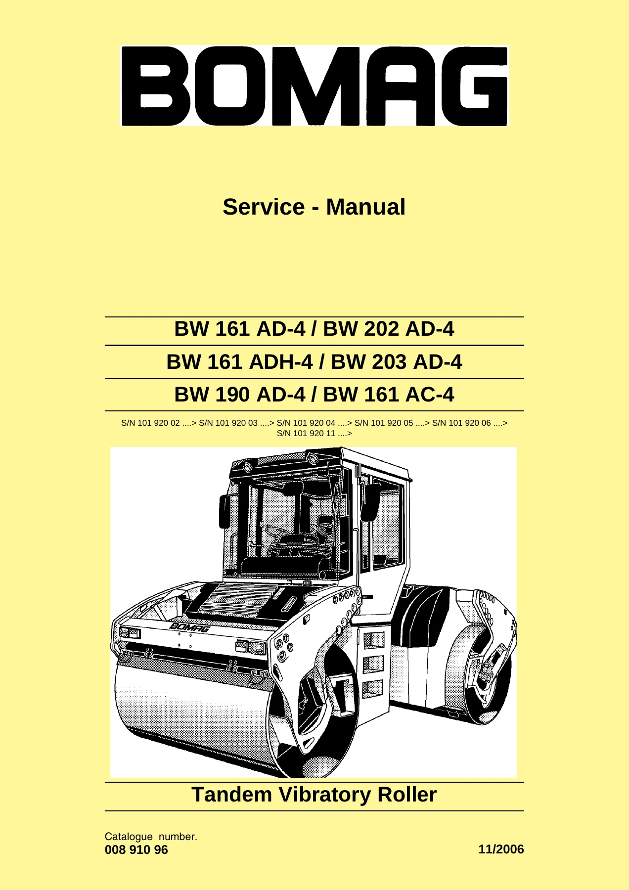
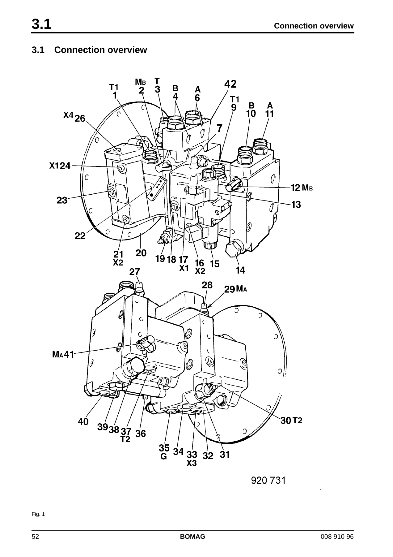
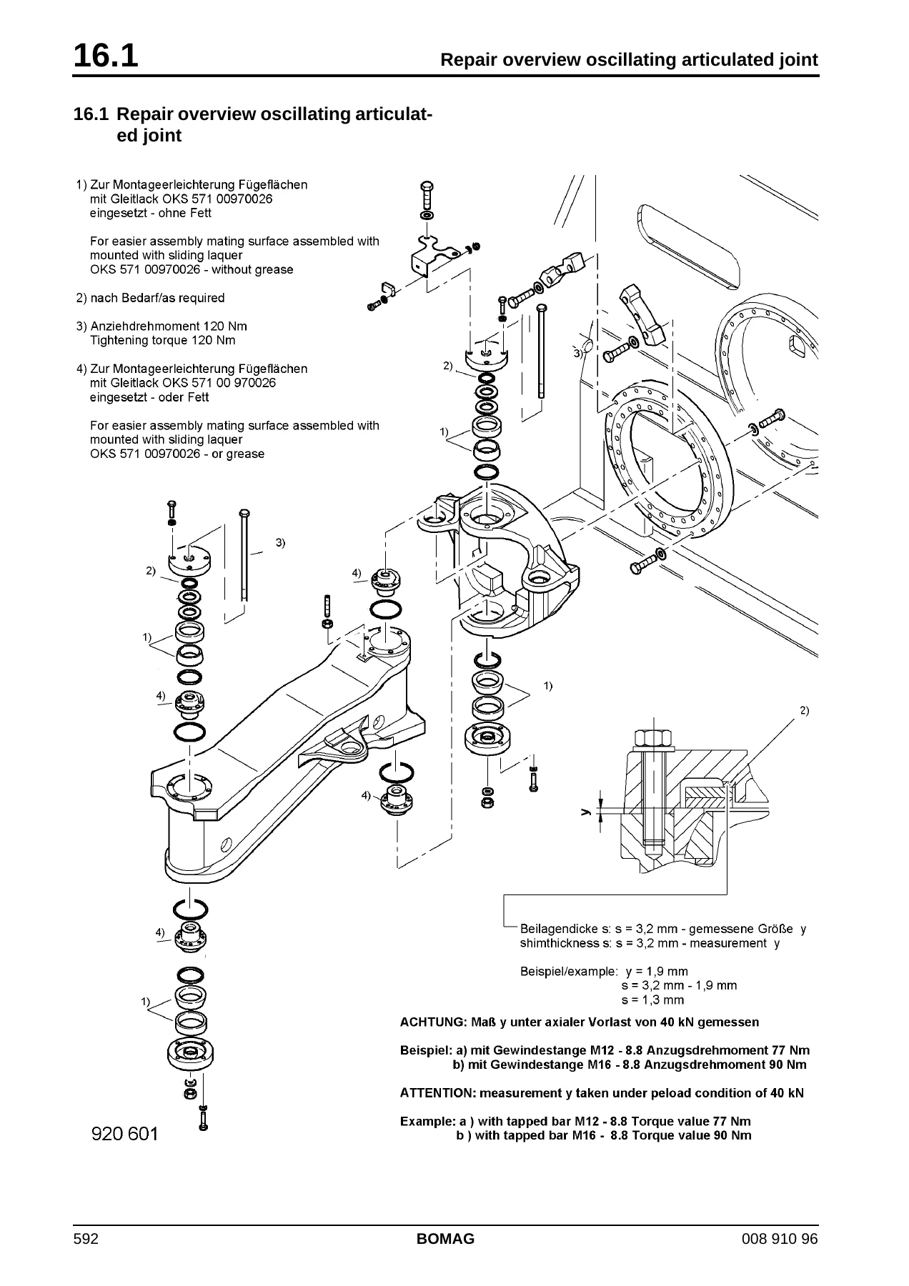
Reviews
There are no reviews yet.