Description
BOMAG BW 216 D-4 and BW 216 PD-4 Single Drum Roller Service Manual 008 911 83 (August 2007)
This download is the BOMAG BW 216 D-4 and BW 216 PD-4 Single Drum Roller Service Manual 008 911 83 (August 2007), the bound workshop book printed under catalogue number 008 911 83 and dated 08/2007. It is written for trained mechanics working on the two title machines: the smooth-drum BW 216 D-4 and the padfoot BW 216 PD-4. The cover identifies the serial groups S/N 101 583 23…… and S/N 101 583 24…… Wiring sheets inside further pin those groups to 101 583 231 001 (BW 216 D-4) and 101 583 241 001 (BW 216 PD-4), with a later diagram set from 101 583 231 023 and 101 583 241 002.
A service-training insert bound into the same file also walks through related series-4 single drum rollers (BW 211 / 213 D-4 and BW 216 / 219 D-4). Treat that chapter as shared training material; the technical-data tables, tests, drum work, and machine-specific diagrams in this book are written around the BW 216 D-4 and BW 216 PD-4.
File Details
- Manual type: Service manual (workshop repair and diagnostics)
- Brand / models: BOMAG BW 216 D-4 and BW 216 PD-4 single drum rollers
- Language: English
- Page count: 974
- File format: PDF
- Catalogue / document number: 008 911 83
- Date: 08/2007 (August 2007)
Chapters Covered
- 1 General — introduction; safety regulations; general repair instructions; tightening torques
- 2 Maintenance — general notes; fuels and lubricants; table of fuels and lubricants; running-in instructions; maintenance chart
- 3 Technical data — dimensions, weights, travel, engine, brakes, steering, vibration, tires, filling capacities, component data
- 4 Connection overview — travel / vibration pump ports and test points
- 5 Tests and adjustments — special tools; travel-pump neutral; travel-circuit pressures; vibrator shaft speeds; vibration-circuit pressures; vibration-motor leakage; steering-circuit pressure
- 6 Flushing and bleeding — flushing tools; travel circuit (pump distribution and axle-motor distribution); vibration circuit; bleeding both circuits
- 7 Fundamental electrics — circuit-diagram reading; terminals; current, voltage, resistance; Ohm’s law; diodes, relays, fuses; batteries; three-phase generator; starter; Telemecanique switch; inductive proximity switches; angle sensor; Deutsch DT/DTM and spring-clamp connectors
- 8 Special tools, electrics
- 9 Electronic modules — BEM (BOMAG Evib-meter); seat contact module
- 10 Speedometer module
- 11 Service training machine — series-4 single drum roller training (BW 211 / 213 D-4 and BW 216 / 219 D-4)
- 12 Engine — TCD 2012 and TCD 2013 descriptions; lubrication, coolant and fuel circuits; Deutz Common Rail (DCR); sensors; EDC16 with EMR 3; EGR; instrument cluster; fault diagnosis and EMR3 fault codes; SerDia; troubleshooting chart; valve adjustment; ribbed V-belt; Deutz special tools
- 13 Air conditioning system — R134a circuit, compressor oil and clutch, evacuation, leak test, charging, troubleshooting, heating / A/C control
- 14 Replacing the cab window panes
- 15 Drum — special tools; repair overview; remove / install; drum repair; change-over weights; rubber buffers and pretension
- 16 Oscillating articulated joint — tools; repair overview; remove / install; dismantle and assemble
- 17 Suppliers documentation — Sauer travel pump series 90R; travel drive series 51; vibration pump 42R 041; vibration motor A10FM; transmission CR; axle DANA 193
- 18 Circuit diagrams — wiring diagram 582 702 14; wiring diagram 582 702 30; hydraulic diagram
Taken together, the book is a full workshop path: identify the machine, service it on a schedule, measure the hydrostatic circuits, overhaul the drum and articulation, diagnose the Deutz EMR 3 engine and the onboard electrics, then confirm the repair against the wiring and hydraulic sheets.
Machines, serial groups, and published specifications
Both title machines share the same basic envelope. Length is 5808 mm, wheelbase 2960 mm, drum diameter 1500 mm, width 2130 mm, and height to the cab roof 2972 mm. Drum shell thickness differs: 35 mm on the BW 216 D-4 and 25 mm on the BW 216 PD-4. Operating weight with ROPS and cabin is 15700 kg (D-4) and 16200 kg (PD-4). Drum axle load is 10400 kg versus 10900 kg; rear axle load is 5300 kg on both. Static linear load on the smooth drum is 48.8 kg/cm.
Travel is hydrostatic on two driven axles, with four ranges: 0–4, 0–5, 0–7 and 0–11 km/h. Maximum gradability is given as 45 % (D-4) and 48 % (PD-4), soil dependent. Service braking is hydrostatic; parking is hydraulic-mechanical. Steering is articulated and hydrostatic. Vibration is a single hydrostatic drum at 30/36 Hz, with amplitudes 1.8/0.95 mm on the D-4 and 1.64/0.82 mm on the PD-4. Tires are 23.1-26/12 TL R3 at 1.4 bar. Ambient operating range is −20 °C to +50 °C. Electrical system voltage is 12 V.
The engine listed for both machines is a water-cooled 4-cylinder Deutz TCD 2013 L04 2V rated 119 kW at 2200 rpm (DIN ISO 3046). Additional engine figures in the same chapter include 4-stroke diesel combustion, low idle 700–800 rpm, high idle 2200–2250 rpm, specific fuel consumption 226 g/kWh, valve clearance 0.4 mm intake / 0.6 mm exhaust, and injection opening pressure DRC / 1600 bar. Filling capacities published with the machine data are engine oil 15 litres (the fuels table lists approx. 15.5 litres including filter), fuel 340 litres, hydraulic oil 60 litres, and coolant 16 litres. Vibration bearings take 2 × 0.8 litres of SAE 15W/40; the drive axle about 11 litres of SAE 90 API GL5; wheel hubs 2 litres per side; axle reduction gear 1.9 litres; drum drive gear 3.2 litres. Air-conditioning charge is 1400 g of R134a.
Hydraulic hardware the tests refer to
Travel pump: Sauer 90R 075 axial-piston swash-plate unit, 75 cm³/rev, 163.65 l/min maximum flow, high-pressure limitation 400 + 26 bar, charge pressure at high idle 26 bar. Drum reduction gear CR 31 at 45.6:1. Drum drive motor Sauer 51C 110 (110 / 55 cm³/rev stages). Axle drive motor Sauer 51D 110 bent-axle unit (110 / 69 cm³/rev). Vibration pump Sauer 42R 041, 41 cm³/rev, start-up 345 + 26 bar, operating pressure around 100 bar depending on soil. Vibration motor Bosch-Rexroth A10FM 45, 45 cm³/rev. Steering / charge pump HY/ZFFS11/16 gear pump, 16 cm³/rev, maximum steering pressure 175 + 26 bar, with a Danfoss OSPC 500 ON steering valve. Rear axle Dana CHC 193/66LD with No-Spin differential, 100 % locking, reduction 65.08.
Chapter 4 maps every port on the combined pump stack — high-pressure A/B, charge, leak-oil L / L1 / L2, frequency solenoids, multi-function valves, and the mechanical neutral setscrews — so a technician can hang gauges without guessing. Chapter 5 then uses those ports: set travel-pump neutral, read charge and high pressure in both directions, check vibrator shaft speed at high and low amplitude, measure vibration start-up and operating pressure, quantify vibration-motor leak-off, and stall-steer to confirm maximum steering pressure.
Maintenance, fuels, and running-in
Approved engine oils are listed under Deutz DQC II-05 with ACEA E3/E5/E7 or E4/E6 and API CG-4/CH-4/CI-4 families. Oil-change interval at those qualities is 500 operating hours, or at least once per year, halved when fuel sulphur exceeds 0.5 % or ambient temperature stays below −10 °C. Hydraulic oil is HV 46 (ISO), HVLP per DIN 51524 Part 3, viscosity index at least 150; ester-based Panolin HLP Synth. 46 is noted as a factory-fill option on request. Drive-axle oil is API GL5 SAE 90. Grease is lithium EP, penetration 2. Diesel specifications include DIN/EN 590, DIN 51 601, BS 2869, ASTM D 975 1-D/2-D and several NATO codes. BOMAG does not approve RME biodiesel; the text still records the consequences if it is used (power loss, paint attack, halved oil interval).
The maintenance chart runs from daily dipstick, water-separator, fuel, hydraulic and coolant checks through 250 / 500 / 1000 / 2000 / 3000 / 6000 hour tasks: engine oil and filters, fuel filters, valve clearance, axle and hub oils, vibration-bearing oil, hydraulic oil and filters (at least every two years), coolant, crankcase ventilation valve, EMR injector test, and combustion-air filter service. Running-in adds a 30-minute V-belt retighten and a 250-hour first oil set plus wheel-nut and mount retighten.
Engine, EMR 3, and air conditioning
Chapter 12 treats series-4 Deutz engines as a family: 4- or 6-cylinder TCD 2013, or 6-cylinder TCD 2012, water-cooled in-line units with two-valve heads, turbocharger, intercooler, internal or timed EGR for EPA/COM Tier/Stage III, and Deutz Common Rail (DCR) under EDC16 / EMR 3. For the BW 216 D-4 / PD-4 the rating table stays on the TCD 2013 L04 2V. The chapter still gives component callouts, lubrication and coolant flow, rail and speed sensors, the instrument cluster, the diagnostic button, the EMR3 fault-code list, SerDia service software notes, a general troubleshooting chart, valve-adjustment angles with and without EGR, and the ribbed fan belt. Special-tool lists for TCD 2012 2V and TCD 2013 2V are included so injector, rail-sensor and wear-gauge work can be done with the published kit numbers.
Complete PDF Bookmark Tree
Complete Bookmarks
The complete bookmarks in the “BOMAG BW 216 D-4 and BW 216 PD-4 Single Drum Roller Service Manual 008 911 83 (August 2007)” are as follows:
+BW 216 D-4 / BW 216 PD-4p. 1
S/N 101 583 23…… S/N 101 583 24p. 1
+Single drum rollerp. 1
1.1 Introductionp. 8
+Safety regulationsp. 9
Important notesp. 9
Generalp. 9
Precautions and codes of conduct for welding workp. 9
Old oilsp. 10
Hydraulicsp. 10
Fuelsp. 11
Hot fuelsp. 11
Synthetic rubberp. 11
Poisonous substancesp. 11
Enginep. 11
Air conditioning systemp. 12
Batteryp. 12
Poisonous substancesp. 13
Special safety regulationsp. 13
+General repair instructionsp. 14
Generalp. 14
Electricsp. 14
Batteryp. 15
Hydraulic systemp. 16
Air conditioning systemp. 17
+Notes on cleanliness for Common Rail enginesp. 18
+Fuel hosesp. 20
+Gaskets and mating surfacesp. 21
+Feather keys and keywaysp. 22
+Ball and roller bearingsp. 22
+Screws and nutsp. 23
Fig. 8 Identification of screwsp. 24
Fig. 9 Identification of nutsp. 24
Fig. 10 Identification of nuts in clock systemp. 25
+Tightening torquesp. 26
+2.1 General notes on maintenancep. 32
Notes on the fuel systemp. 32
Notes on the engine performancep. 32
Notes on the hydraulic systemp. 32
Notes on the cooling systemp. 32
+2.2 Fuels and lubricantsp. 33
+Engine oilp. 33
Fuelsp. 34
Coolant, anti-freeze agentp. 35
Hydraulic oilp. 35
Oil for drive axlep. 35
Lubrication greasep. 35
2.3 Table of fuels and lubricantsp. 36
2.4 Running-in instructionsp. 37
+2.5 Maintenance chartp. 38
3 Technical datap. 41
Technical datap. 42
Fig. 12p. 42
Noise valuep. 45
+Vibration valuep. 45
4 Connection overviewp. 47
Connection overview
+Fig. 1 Travel pumpp. 48
1 Control solenoid, high frequencyp. 49
2 Control solenoid, low frequencyp. 49
3 Multi-function valve 400 bar (boost check and pressure relief valve), travel systemp. 49
4 Connection, charge pressure to brake solenoid valve, travel speed range selection and charge oil supply for vibration pumpp. 49
5 Multi-function valve 400 bar (boost check and pressure relief valve), travel systemp. 49
6 Setscrew, mechanical neutral positionp. 49
7 Connection L, leak oil connection to vibration pumpp. 49
8 Lever, travel controlp. 49
9 Pilot pressure test portp. 49
10 High pressure port B, high pressure reversep. 49
11 Charge pressure relief valve, 26 barp. 49
12 Adjustment screw, low frequencyp. 49
13 Connection L2, leak oil to tankp. 49
14 Pressure test port MB, high frequencyp. 49
15 High pressure test port MA, low frequencyp. 49
16 High pressure port A, low frequencyp. 49
17 High pressure port B, high frequencyp. 49
18 Charge pump, internalp. 49
19 Connection L2, to drum drive motor (flushing)p. 49
20 Adjustment screw, high frequencyp. 49
21 Connection D, charge pressure to filterp. 49
22 Multi function valve 345 bar (boost check and pressure relief valve), vibration drive high frequencyp. 49
23 Connection S, suction line charge pump from hydraulic oil tankp. 49
24 Multi function valve 345 bar (boost check and pressure relief valve), vibration drive low frequencyp. 49
25 Charge pressure relief valve, vibration pump (blocked)p. 49
26 Connection E, charge oil from travel pumpp. 49
27 Connection L1, leak oil connection to travel pumpp. 49
28 Pressure test port MB, high pressure reversep. 49
29 Charge oil from filterp. 49
30 Pressure test port MA, high pressure forwardp. 49
31 High pressure port A, high pressure forwardp. 49
32 Setscrew, mechanical neutral position, vibrationp. 49
33 Leak oil connection D, leak oil from axle drive motorp. 49
34 Leak oil connection A, leak oil from travel pumpp. 49
35 Leak oil connection G, leak oil from drum drive motorp. 49
36 Leak oil connection F, leak oil from vibration motorp. 49
37 Radiator inletp. 49
5 Tests and adjustmentsp. 51
+5.1 Special tools, tests and adjustmentsp. 52
Fig. 1p. 52
Fig. 2p. 52
Fig. 3p. 52
Fig. 4p. 52
Fig. 5p. 53
Fig. 6p. 53
Fig. 7p. 53
Fig. 8p. 53
Fig. 9p. 54
Fig. 10p. 54
Fig. 11p. 54
Fig. 12p. 54
Fig. 13p. 55
Fig. 14p. 55
+5.2 Checking / adjusting the neutral positions of the travel pumpp. 56
Fig. 1p. 56
Fig. 2p. 56
Fig. 3p. 56
Fig. 4p. 57
Fig. 5p. 57
Fig. 6p. 57
Fig. 7p. 57
+5.3 Pressure tests in the travel circuitp. 58
Fig. 1p. 58
Fig. 2p. 58
Fig. 3p. 58
Fig. 4p. 59
+5.4 Checking / adjusting the vibrator shaft speedsp. 60
Fig. 1p. 60
Fig. 2p. 60
Fig. 3p. 60
+5.5 Pressure measurements in the vibration circuitp. 61
+5.6 Check the leakage rate of the vibration motorp. 62
Fig. 1p. 62
Fig. 2p. 62
Fig. 3p. 62
+5.7 Pressure test in steering circuitp. 63
Fig. 1p. 63
Fig. 2p. 63
Fig. 3p. 63
Fig. 4p. 64
+Fig. 5p. 64
6 Flushing and bleedingp. 65
+6.1 Special tools for flushingp. 66
+Fig. 1p. 66
1. Filling and filtering unit with oil bagp. 66
2. Filter elementp. 66
+Fig. 2p. 66
3. Flushing filter (S connection)p. 66
4. Filter element 1mp. 66
5. Flushing hose 20S – 25S (2 pieces)p. 66
6. Screw socket R1“ – 25S (2 pieces)p. 66
+Fig. 3p. 66
7. Flushing filter (L connection)p. 66
8. Filter elementp. 66
9. Flushing hose 15L (2 pieces)p. 66
10. Screw socket R3/4“ — 15L (2 pieces)p. 66
+Fig. 4p. 66
11. SAE-flange 1“ – 20Sp. 66
12. O-ringp. 66
+Fig. 5p. 67
13. Flanged plate 1“ – 25Sp. 67
14. O-ringp. 67
+Fig. 6p. 67
15. Reducing fitting 18L – 15Lp. 67
+Fig. 7p. 67
16. Reducing fitting 25S – 20Sp. 67
+Fig. 8p. 67
17. Reducing fitting 20S – 16Sp. 67
+Fig. 9p. 68
18. Connecting socket 15Lp. 68
+Fig. 10p. 68
19. Connecting socket 18Lp. 68
+Fig. 11p. 68
20. Connecting socket 16Sp. 68
+Fig. 12p. 68
21. Connecting fitting 20Sp. 68
+Fig. 13p. 69
22. Connecting fitting 25Sp. 69
+Fig. 14p. 69
23. Angular fitting 18Lp. 69
+Fig. 15p. 69
24. Elbow fitting 16Lp. 69
+Fig. 16p. 69
+Fig. 17p. 70
+Fig. 18p. 70
27. Pipe connection 16S – 16Sp. 70
+Fig. 19p. 70
28. Connecting hose 15Lp. 70
+6.2 Flushing – generalp. 71
Changing a componentp. 71
+Chips (abrasion) in the oilp. 71
l Open and clean all components in the oil circuit, replace if necessary.p. 71
l Clean all high pressure hoses in the oil circuit, replace if necessary.p. 71
l If abrasion is found in the travel circuit you should also flush the vibration circuit.p. 71
l If abrasion is found in the vibration circuit you should also flush the travel circuit.p. 71
+Before flushingp. 71
+Fig. 1p. 71
l Change the hydraulic oil filter element (1).p. 71
+Fig. 2p. 71
l Filter the tank content with the filling and filtering unit and pump it into the oil bag.p. 71
l Mark all hoses and disconnect them from the hydraulic oil tank.p. 71
l Clean the oil tank thoroughly from inside, if necessary remove the complete tank cover.p. 71
l Reconnect all hoses.p. 71
l Fill the hydraulic oil tank again with the filling and filtering unit.p. 71
+Bleedingp. 71
+Fig. 3p. 71
l Always bleed closed hydraulic circuits if lines had been removed or connected.p. 71
+Servicing the flushing filter kitp. 72
+Fig. 4p. 72
l Replace the filter element of the flushing filter when the red control pin of the contamination indicator is pressed out during the filtering process.p. 72
l Clean hoses and connections and store the flushing kit in a clean and protected environment.p. 72
+Flushing schematic travel circuit (distribution travel pump)
1 Elbow union (tool)p. 74
2 Connecting union (tool)p. 74
3 Drum drive motorp. 74
4 Axle motorp. 74
5 Screw socket R1 – 25S (tool)p. 74
6 Flushing hose 25S – 20S (tool)p. 74
7 Flushing hose 25S – 20S (tool)p. 74
8 Flushing filter with filter element 1m (tool)p. 74
9 Elbow union (tool)p. 74
10 Reducing fitting (tool)p. 74
11 Travel pumpp. 74
12 High pressure hose (B, drum drive motor reverse)p. 74
13 High pressure hose (A, drum drive motor forward)p. 74
14 High pressure hose (B, axle motor reverse)p. 74
15 High pressure hose (A, axle motor forward)p. 74
16 High pressure hose (B, axle motor reverse)p. 74
17 High pressure port (B, drum drive motor reverse)p. 74
18 Flushing hose 25S – 20S (tool)p. 74
19 Flushing hose 25S – 20S (tool)p. 74
+6.4 Flushing the travel circuit (travel pump distribution)p. 75
+Flushing the drum drivep. 75
+Fig. 1p. 75
1. Disconnect the high pressure hose 12 (see chapter "Flushing schematic – travel circuit") from the travel pump (high pressure port 17) and connect it with the flushing hose (7) (flushing filter inlet "IN").p. 75
2. Connect the flushing hose (6) (flushing filter outlet "OUT") to the (high pressure port 17) on the travel pump.p. 75
+Fig. 2p. 75
3. Take the drum drive motor out of the hydraulic circuit by joining the high pressure hoses (12 and 13) on the drum drive motor together.p. 75
Fig. 3p. 76
+Fig. 4p. 76
4. Block drums and wheels with suitable chocks.p. 76
Fig. 5p. 76
+Fig. 6p. 76
5. Start the engine and shift the travel lever to travel direction forward.p. 76
6. Perform the flushing process at various engine speeds for approx. 10 minutes.p. 76
7. Shut down the engine.p. 76
8. Reconnect the hydraulic hoses (12 and 13) to the drum drive motor.p. 76
+Fig. 7p. 77
9. Jack up the front of the machine, so that the drum can rotate freely.p. 77
10. Secure the rear wheels with chocks.p. 77
11. Pre-select the slow speed range.p. 77
Fig. 8p. 77
+Fig. 9p. 77
12. Start the engine, run it with maximum speed and shift the travel lever to travel direction forward.p. 77
13. Run the flushing procedure for approx. 10 minutes. During this process keep changing the pump flow by shifting the travel lever several times between full and halve forward travel.p. 77
14. Shut down the engine.p. 77
15. Remove the flushing filter and reconnect the high pressure lines.p. 77
+Flushing the axle drivep. 78
+Fig. 10p. 78
16. Disconnect the high pressure hose 14 (see chapter "Flushing schematic – travel circuit") from the travel pump (high pressure port 16) and connect it with the flushing hose (18) (flushing filter inlet "IN").p. 78
17. Connect the flushing hose (19) (flushing filter outlet "OUT") to the (high pressure port 16) on the travel pump.p. 78
+Fig. 11p. 78
18. Take the axle drive motor out of the hydraulic circuit by joining the high pressure hoses (14 and 15) on the axle drive motor together.p. 78
Fig. 12p. 78
+Fig. 13p. 79
19. Block drums and wheels with suitable chocks.p. 79
Fig. 14p. 79
+Fig. 15p. 79
20. Start the engine and shift the travel lever to travel direction forward.p. 79
21. Perform the flushing process at various engine speeds for approx. 10 minutes.p. 79
22. Shut down the engine.p. 79
23. Reconnect the hydraulic hoses (14 and 15) to the axle drive motor.p. 79
+Fig. 16p. 79
24. Jack up the rear of the machine, so that the wheels can rotate freely.p. 79
25. Secure the drum with wheel chocks.p. 79
26. Pre-select the slow speed range.p. 79
Fig. 17p. 80
+Fig. 18p. 80
27. Start the engine, run it with maximum speed and shift the travel lever to travel direction forward.p. 80
28. Run the flushing procedure for approx. 10 minutes. During this process keep changing the pump flow by shifting the travel lever several times between full and halve forward travel.p. 80
29. Shut down the engine.p. 80
30. Remove the flushing filter and reconnect the high pressure lines.p. 80
31. Bleed the travel circuit (see corresponding chapter).p. 80
32. After completing the bleeding process circulate the tank content with the filtering unit for another 15 minutes.p. 80
+Fig. 19p. 80
33. Check the hydraulic oil level in the tank, fill up if necessary.p. 80
34. Check all connections for leaks with the engine running (visual inspection).p. 80
35. Perform a test drive, load the travel system in forward and reverse, e.g. by driving uphill or starting on a gradient.p. 80
36. Check all ports and connections for leak tightness (visual inspection).p. 80
+Flushing schematic travel circuit (distribution axle motor)
1 Elbow union (tool)p. 85
2 Connecting union (tool)p. 85
3 Drum drive motorp. 85
4 Axle motorp. 85
5 Screw socket R1 – 25S (tool)p. 85
6 not usedp. 85
7 not usedp. 85
8 Flushing filter with filter element 1m (tool)p. 85
9 not usedp. 85
10 Reducing fitting (tool)p. 85
11 Travel pumpp. 85
12 High pressure hose (drum drive motor reverse)p. 85
13 High pressure hose (drum drive motor forward)p. 85
14 High pressure hose (B, axle motor reverse)p. 85
15 High pressure hose (A, axle motor forward)p. 85
16 High pressure hose (B, axle motor reverse)p. 85
17 not usedp. 85
18 Flushing hose 25S – 20S (tool)p. 85
19 Flushing hose 25S – 20S (tool)p. 85
+6.6 Flushing the travel circuit (axle motor distribution)p. 86
+Flushing the drum drivep. 86
+Fig. 1p. 86
1. Disconnect the high pressure hose 14 (see chapter "Flushing schematic – travel circuit") from the travel pump (high pressure port 16) and connect it with the flushing hose (19) (flushing filter inlet "IN").p. 86
2. Connect the flushing hose (18) (flushing filter outlet "OUT") to the (high pressure port 16) on the travel pump.p. 86
+Fig. 2p. 86
3. Take the drum drive motor out of the hydraulic circuit by joining the high pressure hoses (12 and 13) on the drum drive motor together.p. 86
Fig. 3p. 87
Fig. 4p. 87
+Fig. 5p. 87
4. Block drums and wheels with suitable chocks.p. 87
+Fig. 6p. 87
5. Start the engine and shift the travel lever to travel direction forward.p. 87
6. Perform the flushing process at various engine speeds for approx. 10 minutes.p. 87
7. Shut down the engine.p. 87
8. Reconnect the hydraulic hoses (12 and 13) to the drum drive motor.p. 87
+Fig. 7p. 88
9. Jack up the front of the machine, so that the drum can rotate freely.p. 88
10. Secure the rear wheels with chocks.p. 88
11. Pre-select the slow speed range.p. 88
Fig. 8p. 88
+Fig. 9p. 88
12. Start the engine, run it with maximum speed and shift the travel lever to travel direction forward.p. 88
13. Run the flushing procedure for approx. 10 minutes. During this process keep changing the pump flow by shifting the travel lever several times between full and halve forward travel.p. 88
14. Shut down the engine.p. 88
+Flushing the axle motorp. 89
+Fig. 10p. 89
15. Jack up the rear of the machine, so that the wheels can rotate freely.p. 89
16. Secure the drum with wheel chocks.p. 89
17. Pre-select the slow speed range.p. 89
Fig. 11p. 89
+Fig. 12p. 89
18. Start the engine, run it with maximum speed and shift the travel lever to travel direction forward.p. 89
19. Run the flushing procedure for approx. 10 minutes. During this process keep changing the pump flow by shifting the travel lever several times between full and halve forward travel.p. 89
20. Shut down the engine.p. 89
21. Remove the flushing filter and reconnect the high pressure lines.p. 89
22. Bleed the travel circuit (see corresponding chapter).p. 89
23. After completing the bleeding process circulate the tank content with the filtering unit for another 15 minutes.p. 89
+Fig. 13p. 90
24. Check the hydraulic oil level in the tank, fill up if necessary.p. 90
25. Check all connections for leaks with the engine running (visual inspection).p. 90
26. Perform a test drive, load the travel system in forward and reverse, e.g. by driving uphill or starting on a gradient.p. 90
27. Check all ports and connections for leak tightness (visual inspection).p. 90
+Flushing schematic for vibration drive
1 Elbow union (tool)p. 91
2 Connecting union (tool)p. 91
3 Vibration motorp. 91
4 Vibration pumpp. 91
5 Screw socket R1 – 25S (tool)p. 91
6 Flushing hose 25S – 20S (tool)p. 91
7 Flushing hose 25S – 20S (tool)p. 91
8 Flushing filter with filter element 1m (tool)p. 91
9 SAE flange (tool)p. 91
10 High pressure hose (B, high frequency)p. 91
11 High pressure hose (A, low frequency)p. 91
+6.8 Flushing the vibration circuitp. 92
+Fig. 1p. 92
1. Disconnect the high pressure hose 10 (see chapter "Flushing schematic – vibration circuit") from the vibration pump (4) and connect it with the flushing hose (7) (flushing filter inlet "IN").p. 92
2. Connect the flushing hose (6) (flushing filter outlet "OUT") to the (high pressure port A) on the vibration pump.p. 92
+Fig. 2p. 92
3. Take the vibration motor out of the hydraulic circuit by joining the high pressure hoses (10 and 11) on the vibration motor together.p. 92
Fig. 3p. 93
+Fig. 4p. 93
4. Block drums and wheels with suitable chocks.p. 93
Fig. 5p. 93
+Fig. 6p. 93
5. Switch on vibration with high frequency.p. 93
6. Start the engine and run it with maximum speed.p. 93
7. Flush the circuit for approx. 10 minutes, thereby switch the vibration on and off at intervals of approx. 30 seconds.p. 93
8. Shut down the engine.p. 93
9. Reconnect the hydraulic hoses (10 and 11) to the vibration motor.p. 93
+Fig. 7p. 94
10. Unscrew the fastening screws for the vibration motor and pull the motor out of the coupling.p. 94
Fig. 8p. 94
+Fig. 9p. 94
11. Start the engine and run it with maximum speed.p. 94
12. Run the flushing procedure for approx. 10 minutes. Switch the vibration on and off at intervals of approx. 30 seconds.p. 94
13. Shut down the engine.p. 94
14. Remove the flushing filter and reinstall the vibration motor.p. 94
15. Bleed the vibration circuit (see corresponding chapter).p. 94
16. After completing the bleeding process circulate the tank content with the filtering unit for another 15 minutes.p. 94
+Fig. 10p. 95
17. Check the hydraulic oil level in the tank, fill up if necessary.p. 95
18. Test drive.p. 95
19. Check all ports and connections for leak tightness (visual inspection).p. 95
+6.9 Bleeding the travel circuitp. 96
1. Install a pressure test hose to the charge pressure test port.p. 96
2. Install a pressure test hose each to the high pressure test ports.p. 96
+Fig. 1p. 96
3. Actuate the emergency stop switch.p. 96
+Fig. 2p. 96
4. Hold the open ends of the pressure test hoses (Fig. 2) into a container.p. 96
5. Operate the starter motor for approx. 30 seconds. Wait one minute and repeat this procedure, until oil starts to run out from the pressure test hoses.p. 96
6. Remove the pressure test hoses.p. 96
+Fig. 3p. 96
7. Unlock the emergency stop switchp. 96
+Fig. 4p. 97
8. Connect a 60 bar pressure gauge to the charge pressure test port (Fig. 4) and run the engine max. 15 seconds at idle speed.p. 97
9. Pause for approx. 30 seconds and keep repeating this procedure, until the gauge shows a constant charge pressure reading.p. 97
+Fig. 5p. 97
10. Start the engine.p. 97
11. Shift the travel lever (Fig. 5) approx. 1/3 to forward direction.p. 97
12. After approx. 1 to 2 minutes shut down the engine for a minute.p. 97
13. After a waiting time of approx. 1 minute keep repeating this procedure, until the indicated charge pressure drops directly to zero when shutting down the engine.p. 97
+6.10 Bleeding the vibration circuitp. 98
1. Install a pressure test hose to the charge pressure test port.p. 98
2. Install a pressure test hose each to the high pressure test ports.p. 98
+Fig. 1p. 98
3. Actuate the emergency stop switch.p. 98
+Fig. 2p. 98
4. Hold the open ends of the pressure test hoses (Fig. 2) into a container.p. 98
5. Crank the engine approx. 10 seconds with the starter motor. Wait one minute and keep repeating this procedure, until oil starts to run out from the pressure test hoses.p. 98
6. Remove the pressure test hoses.p. 98
+Fig. 3p. 98
7. Unlock the emergency stop switchp. 98
+Fig. 4p. 99
8. Connect a 60 bar pressure gauge to the charge pressure test port (Fig. 4) and run the engine max. 15 seconds at idle speed.p. 99
9. Wait for approx. 30 seconds and repeat the procedure, until the pressure gauge shows a constant charge pressure.p. 99
+Fig. 5p. 99
10. For bleeding switch on vibration with high frequency (Fig. 5).p. 99
11. Start the engine.p. 99
12. After running the engine 1 to 2 minutes pause for approx. one minute.p. 99
13. After a waiting time of approx. 1 minute keep repeating this procedure, until the indicated charge pressure drops directly to zero when shutting down the engine.p. 99
7 Fundamental electricsp. 101
+7.1 Understanding circuit diagramsp. 102
Fig. 6 Table of contentsp. 102
Fig. 7 Function groupsp. 103
Fig. 8 Current pathsp. 104
Fig. 9 List of componentsp. 104
Fig. 10 Graphic symbolp. 105
Fig. 11 Graphic symbolp. 105
7.2 Terminal designationsp. 106
+7.3 Current and voltagep. 110
Generalp. 110
+Voltagep. 110
+Currentp. 111
+Types of currentp. 111
Fig. 1 Direct current (D.C.)p. 111
Fig. 2 Alternating current (A.C.)p. 111
Fig. 3 Pulsating direct currentp. 111
Fig. 4 PWMp. 112
Fig. 5 CANp. 113
+7.4 Resistancep. 114
+Resistance and voltage dropp. 114
Fig. 1 Various size resistorsp. 114
Fig. 2 Potentiometer, infinitely adjustable resistorp. 114
+Unnecessary resistancesp. 114
Fig. 1 Screw-type terminalsp. 114
Fig. 2 Spring clampsp. 114
Fig. 3p. 115
Fig. 4 Balistol oilp. 115
Fig. 5p. 115
+7.5 Series / parallel connectionp. 116
Fig. 1 Series connectionp. 116
Fig. 2p. 116
Fig. 3 Parallel connectionp. 117
Fig. 4p. 117
+7.6 Ohm's lawp. 118
+7.7 Electrical energyp. 118
+7.8 Formula diagramp. 119
Fig. 1 Formula diagramp. 119
+7.9 Metrologyp. 120
+Test lampsp. 120
Fig. 1 Test lampp. 120
Fig. 2 Diode test lampp. 120
+Multimeterp. 120
Fig. 1 Multimeterp. 120
Fig. 2 Voltage measurementp. 121
Fig. 3 Current measurementp. 121
+Clip-on measuring instrumentp. 121
Fig. 1 Clip-on measuring instrumentp. 121
+Magnet testerp. 122
Fig. 1 Magnet testerp. 122
+7.10 Diodes, relays, fusesp. 122
+Diodesp. 122
Fig. 1p. 122
Fig. 2 Marking of the cathodep. 122
Fig. 3 Diode circuitryp. 123
Fig. 4 LEDp. 123
+Relaysp. 124
Fig. 1 Relaysp. 124
Fig. 2 Relay circuitryp. 124
+Fusesp. 124
+7.11 Batteriesp. 125
Fig. 1p. 125
Fig. 2p. 125
Fig. 3 Reading the acid levelp. 126
Fig. 4 Battery and generator testerp. 126
Fig. 5 Charge conditionp. 127
+7.12 Three-phase generatorp. 128
+Generalp. 128
Fig. 6 Rotor with claw polesp. 128
Fig. 7 Stator with 3 windingsp. 128
Fig. 8 3-phase currentp. 129
Fig. 9 Regulator with diode plate and rectifier diodesp. 130
+Checking the generatorp. 130
Fig. 10 Connections on the three-phase alternator (exemplary design)p. 131
Fig. 11 Rotorp. 132
Fig. 12 Statorp. 132
Fig. 13p. 133
Fig. 14p. 133
Fig. 15p. 134
Fig. 16p. 134
Fig. 17p. 134
Fig. 18p. 134
+7.13 Electric starterp. 136
Fig. 1 Electric starterp. 136
Fig. 2 Switching position during engagementp. 137
Fig. 3 Switching position during startingp. 137
+7.14 Telemecanique switchp. 139
Fig. 1 Terminal designationsp. 139
Fig. 2 Disassemblyp. 140
Fig. 3 Folding down the switch blockp. 140
Fig. 4 Pulling out the front elementp. 140
Fig. 5 Assemblyp. 141
Fig. 6 Observe the marks.p. 141
Fig. 7 Assemble the switch blockp. 141
+7.15 Inductive proximity switchesp. 142
Fig. 8p. 142
Fig. 9 PNP circuitryp. 142
Fig. 10 NPN circuitryp. 142
Fig. 11p. 142
Fig. 12 Circuit diagram, making contactp. 143
+7.16 Angle sensor with current outputp. 143
Fig. 1 Sensorp. 143
Fig. 2 Connection diagramp. 144
7.17 Plug connectorsp. 144
+7.18 Deutsch plug, series DT and DTMp. 145
+Generalp. 145
Fig. 3 Crimp connectionsp. 145
+DT Seriesp. 145
Fig. 1 DT plug connectionp. 145
Fig. 2 DT Seriesp. 145
Fig. 3 Sectional drawingp. 145
Fig. 4p. 146
Fig. 5p. 147
Fig. 1 DTM plug connectionp. 148
Fig. 2 DTM Seriesp. 148
Fig. 3 Sectional drawingp. 148
Fig. 4p. 149
Fig. 5p. 150
+7.19 Plugs and terminals in spring clamping technologyp. 151
+Generalp. 151
Fig. 1p. 151
Fig. 2 That's how it worksp. 151
Fig. 3 Connecting clampp. 151
Fig. 4 That's how it worksp. 152
Fig. 5 Test adapterp. 152
Fig. 6 That's how it worksp. 153
Fig. 7 X-COM plug with measuring cablep. 153
Fig. 8 X-COM plug plugged onto the series clampp. 153
8 Special tools, electricsp. 155
+8.1 Special tools, electricsp. 156
Fig. 9p. 156
Fig. 10p. 156
Fig. 11p. 156
Fig. 12p. 156
Fig. 13p. 157
Fig. 14p. 157
Fig. 15p. 157
Fig. 16p. 158
Fig. 17p. 158
Fig. 18p. 158
Fig. 19p. 158
Fig. 20p. 159
Fig. 21p. 159
Fig. 22p. 159
Fig. 23p. 159
Fig. 24p. 160
Fig. 25p. 160
Fig. 26p. 160
Fig. 27p. 160
Fig. 28p. 161
Fig. 29p. 161
Fig. 30p. 161
Fig. 31p. 161
Fig. 32p. 162
Fig. 33p. 162
Fig. 34p. 162
Fig. 35p. 162
Fig. 36p. 163
Fig. 37p. 163
Fig. 38p. 163
Fig. 39p. 163
Fig. 40p. 164
+Fig. 41p. 164
9 Electronic modulesp. 165
+9.1 Electrics BEM (BOMAG Evib-meter)p. 167
BOMAG Evib-meter (BEM)p. 168
+9.2 Seat contact modulep. 229
10 Speedometer Modulep. 237
+10.1 Speedometer modulep. 238
+Fig. 1 Speedometer modulep. 238
11 Service Trainingp. 241
+11.1 Service Training Machinep. 243
+12.1 Diesel enginep. 306
Fig. 1 Deutz diesel engine TCD 2012 and 2013p. 306
+12.2 Engine description TCD 2012p. 307
Fig. 1 Deutz diesel engine TCD 2012, right hand sidep. 307
Fig. 2 Deutz diesel engine TCD 2012, left hand sidep. 308
+12.3 Engine description TCD 2013, 4 and 6 cylinderp. 309
Fig. 1 Deutz diesel engine TCD 2013 L04 2V, right hand sidep. 309
Fig. 2 Deutz diesel engine TCD 2013 L04 V2, left hand sidep. 310
Fig. 3 Deutz diesel engine TCD 2013 L06 2V, right hand sidep. 311
Fig. 4 Deutz diesel engine TCD 2013 L06 2V, left hand sidep. 312
+12.4 Lubrication oil circuit TCD 2012 / 2013p. 313
Fig. 1 Lubrication oil diagramp. 313
+12.5 Coolant circuit TCD 2012 / 2013p. 314
Fig. 1 Fuel diagramp. 314
+12.6 Fuel system TCD 2012 / 2013p. 315
Fig. 1 Coolant diagramp. 315
Fig. 2 Fuel pre-filterp. 316
Fig. 3 TCD 2013 Fuel systemp. 317
Fig. 4 TCD 2012 Fuel systemp. 318
+12.7 Deutz Common Rail (DCR) injection system for TCD 2012 / 2013p. 319
Fig. 1 TCD 2012 and 2013p. 319
Fig. 2 Schematic of the Deutz Common Rail System "DCR"p. 320
Fig. 3 Fuel Control Unit FCUp. 321
Fig. 4 High pressure pumpp. 321
Fig. 5 Injectorp. 322
Fig. 6 Excerpt from the wiring diagramp. 322
Fig. 7 TCD 2013p. 323
Fig. 8 Diesel engine TCD 2012p. 324
+12.8 Sensors TCD 2012 / 2013p. 325
Fig. 1 Sensors TCD 2013p. 325
Fig. 2 Sensors TCD 2013p. 326
Fig. 3 Wiring loom TCD 2013p. 326
Fig. 4 Crankshaft speed sensor TCD 2012p. 328
Fig. 5 Crankshaft speed sensorp. 328
Fig. 6 Crankshaft speed sensor TCD 2013p. 329
Fig. 7 Crankshaft speed sensorp. 329
Fig. 8 Camshaft speed sensor TCD 2012/2013p. 330
Fig. 9 Camshaft speed sensorp. 330
Fig. 10 Electric wiring diagram, page 004p. 331
Fig. 11 Speed sensorp. 331
Fig. 12 TCD 2012p. 332
Fig. 13 TCD 2013p. 332
Fig. 14 Charge air pressure and temperature sensorp. 333
Fig. 15 Electric wiring diagram, page 004p. 333
Fig. 16 TCD 2012p. 334
Fig. 17 TCD 2013p. 334
Fig. 18 Electric wiring diagram, page 004p. 335
Fig. 19 Assignment of connectionsp. 335
Fig. 20 TCD 2013p. 336
Fig. 21 Electric wiring diagram, page 004p. 336
Fig. 22 TCD 2012p. 337
Fig. 23 Electric wiring diagram, page 004p. 337
Fig. 24 TCD 2012p. 338
Fig. 25 TCD 2013p. 338
Fig. 26 Electric wiring diagram, page 004p. 339
Fig. 27 Connecting plugp. 339
+12.9 Engine control EDC16 with EMR 3 for TCD 2012 / 2013p. 340
Fig. 1 EDC 16 – EMR 3 TCD 2012 and 1013p. 340
Fig. 2 EMR 3 – connecting plug TCD 2012 and 2013p. 341
Fig. 3 Connecting plug EMR3p. 341
Fig. 4 Electric wiring diagram, page 004p. 342
Fig. 5 Electric wiring diagram, page 004p. 343
Fig. 6 EMR3-position in the machine under the operator's standp. 344
+12.10 Exhaust gas recirculation TCD 2012 / 2013p. 345
Fig. 1 Exhaust/intake valve control TCD 2012 / 2013p. 345
+12.11 Engine monitoring, instrument cluster TCD 2012 / 2013p. 346
Fig. 1p. 346
Fig. 1 New instrument clusterp. 346
Fig. 2p. 347
+12.12 Fault diagnosis TCD 2012 / 2013p. 348
Fig. 1p. 348
Fig. 1 Control light and diagnostics buttonp. 348
Fig. 2p. 349
Fig. 3p. 349
12.13 EMR3 List of fault codesp. 350
+12.14 SerDia Service-Software TCD 2012 / 2013p. 360
Fig. 1 Service-Software TCD 2012 / 2013p. 360
Fig. 2 Serdia connection socket electric cabinetp. 361
Fig. 3 Error logp. 362
12.15 General trouble shooting chart TCD 2012 / 2013p. 363
+12.16 Valve adjustment TCD 2012 / 2013p. 365
Fig. 1 TCD 2012 and 2013p. 365
Fig. 1 TCD 2012 / 2013 Valvesp. 365
Fig. 2 TCD 2012 / 2013 Valvesp. 367
+12.17 Ribbed V-belt – fan drive TCD 2012 / 2013p. 368
Fig. 1 Ribbed V-beltp. 368
12.18 Special tools, Deutz engine (TCD 2012 2V)p. 369
+12.19 Special tools, Deutz engine (TCD 2013 2V)p. 384
13 Air conditioning systemp. 403
+13.1 Physical basicsp. 404
Fig. 1p. 404
Fig. 2p. 404
+Pressure and boiling pointp. 405
Fig. 3 Steam pressure curvep. 405
Fig. 4 Pressure – Temperature Diagramp. 405
+13.2 Refrigerant R134ap. 407
Environmental aspectsp. 408
13.3 Compressor oil / refrigeration oilp. 408
+13.4 Working principle of the air conditioning systemp. 409
Fig. 1 Principle sketch of an air conditioning systemp. 409
+13.5 Monitoring devicesp. 409
Fig. 2 Monitoring chain consisting of:p. 410
+13.6 Description of componentsp. 410
+Compressorp. 410
+Condenserp. 411
+Dryer / filter / fluid container / inspection glassp. 412
Fig. 1p. 412
Fig. 2p. 412
Fig. 3p. 412
+Expansion valvep. 413
+Evaporatorp. 414
+Defroster thermostatp. 414
+Pressure switchp. 415
Pipes and hosesp. 415
+13.7 Checking the compressor oil levelp. 416
+Checking the compressor oil level / refrigeration oil levelp. 416
+13.8 Checking the magnetic clutchp. 417
Fig. 1p. 417
Fig. 2 Measuring the air gapp. 417
+Cross-section of magnetic clutchp. 417
Fig. 3 Cross-section of magnetic clutchp. 417
13.9 Inspection and maintenance workp. 418
+13.10 Checking, replacing the refrigerant compressor V-beltp. 418
+Check the V-beltp. 418
+Tighten the V-belt.p. 418
Changing the V-beltp. 419
+13.11 Service the air conditioningp. 419
+Cleaning the condenserp. 419
+Checking the refrigerant levelp. 419
Fig. 7p. 420
Fig. 8p. 420
Fig. 9p. 420
Fig. 10p. 420
+Checking the moisture level of the drying agentp. 421
+Checking the condition of the drier/collector unitp. 421
13.12 Drying and evacuationp. 422
13.13 Emptying in case of repairp. 422
+13.14 Leak testp. 423
Fig. 1 Electronic leak testerp. 423
Fig. 2 Soap bubble testp. 423
+13.15 Filling instructionsp. 424
Fig. 1p. 425
Filling instructionsp. 426
+13.16 Trouble shooting in refrigerant circuit, basic principlesp. 427
+Basic principlesp. 427
Fig. 2 Pressure gaugep. 427
Fig. 3 Absolute pressure gaugep. 428
Overheatingp. 428
+Supercoolingp. 428
Fig. 1 Refrigerant circuit with t, h- diagramp. 430
+13.17 Trouble shooting, refrigerant circuit diagramp. 431
Fig. 1 Refrigerant circuit diagramp. 431
+13.18 Trouble shooting procedurep. 432
+Procedurep. 432
Fig. 2 Flow diagram with measuring pointsp. 433
Fig. 3p. 436
Fig. 4p. 437
Fig. 5p. 438
Fig. 6p. 439
Steam table for R134a
+13.20 Heating control / air conditioning controlp. 447
14 Replacing the cab window panesp. 453
Assembly of window panes
+Fig. 1p. 454
1 Glass panesp. 454
2 Fastening elementp. 454
3 Fixing washer and spacerp. 454
4 Washerp. 454
5 Hexagon nut, self lockingp. 454
6 Protective capp. 454
14.2 Special toolsp. 455
+Fig. 1p. 455
1. Locking handle for fastening elementp. 455
+Fig. 2p. 455
2. Suction lifterp. 455
14.3 Auxiliary materialsp. 456
+Fig. 1p. 456
+Fig. 2p. 456
4. Window glass bonding agentp. 456
+Fig. 3p. 456
+Fig. 4p. 457
6. Silicone sealantp. 457
14.4 Removing and installing the window panep. 458
+Fig. 1p. 458
1. Pull large glass rests off the bonding strip (Fig. 1).p. 458
+Fig. 2p. 458
2. Clean the sealing surfaces from any adhesive material (Fig. 2).p. 458
3. Use a cutter to remove adhesive residues with glass rests.p. 458
4. Cover places without adhesive residues with an activator.p. 458
+Fig. 3p. 458
5. Insert the fastening element with washer into the bore in the glass pane (Fig. 3).p. 458
+Fig. 4p. 459
6. Turn the fixing and spacer washer hand-tight onto the thread of the fastening element (Fig. 4).p. 459
+Fig. 5p. 459
7. Lay an approx. 1 cm high triangular bead of glass pane bonding agent on the inside of the pane, approx. 1.5 cm away from the edge (Fig. 5).p. 459
+Fig. 6p. 459
8. Attach the suction lifter to the outside of the pane (Fig. 6).p. 459
9. Install the window pane so that the fastening elements fit into the bores of the fastening bars.p. 459
10. Press the glass pane against the sealing surface.p. 459
+Fig. 7p. 459
11. Assemble the washer and the self-locking hexagon nut.p. 459
12. Fasten the window pane to the fastening bar using a locking handle and a ring spanner (Fig. 7).p. 459
13. Press the protective cap onto the hexagon nut.p. 459
+Fig. 8p. 460
14. Remove the suction lifter (Fig. 8).p. 460
+Fig. 9p. 460
15. Clean the joining edges on the window pane (Fig. 9).p. 460
16. Mask the upper and lower contact areas to the cabin.p. 460
+Fig. 10p. 460
17. Apply silicone sealant evenly and under pressure first to the inside joint edge (Fig. 10).p. 460
+Fig. 11p. 460
18. Then apply silicone sealant evenly and under pressure to the outside joint edge (Fig. 11).p. 460
+Fig. 12p. 461
19. Then spray the joints from inside and outside with water containing washing up liquid (Fig. 12).p. 461
+Fig. 13p. 461
20. Treat the inside joint (Fig. 13)p. 461
+Fig. 14p. 461
21. and the outside joint (Fig. 14) with a scraper or a spattle.p. 461
15 Drump. 463
+15.1 Special tools, drum, single drum rollersp. 464
+Fig. 1p. 464
1. Disassembly device for side platep. 464
+Fig. 2p. 464
2. Assembly device for side platep. 464
+Fig. 3p. 464
3. Assembly device for coupling hub and flanged hubp. 464
+Fig. 4p. 465
4. Pressing plate for cylinder roller bearingp. 465
+Fig. 5p. 465
5. Pressing plate for travel bearingp. 465
+Fig. 6p. 465
6. Pressing bushing for radial sealp. 465
+Fig. 7p. 465
7. Lifting device for exciter unitp. 465
+Repair overview for drum
+Fig. 1p. 466
1 Rubber bufferp. 467
2 Vibration bearingsp. 467
3 Housing cover, basic weightp. 467
4 Flangep. 467
5 Flanged housingp. 467
6 Coupling hubp. 467
7 Mechanical sealp. 467
8 Flanged hubp. 467
9 Vibration motorp. 467
10 Compensation platesp. 467
11 Spacer blockp. 467
12 Rectangular rubber bufferp. 467
13 Side platep. 467
14 Travel bearingsp. 467
15 Oil level inspection plugp. 467
16 Oil drain plugp. 467
17 Basic weightp. 467
18 Change-over weightp. 467
19 Radial sealp. 467
20 Vibrator shaftp. 467
21 Fanp. 467
22 Drum shellp. 467
Fig. 2p. 468
Fig. 3p. 469
Fig. 4p. 470
Fig. 5p. 471
Fig. 6p. 472
Fig. 7p. 473
Fig. 8p. 474
+15.3 Removing and installing the drump. 475
Fig. 1p. 475
Fig. 2p. 475
+Removing the drump. 475
+Fig. 3p. 475
8. Mark the hydraulic hoses (Fig. 3)on the travel motor and disconnect them from the ports.p. 475
9. Close all hydraulic hoses and motor ports with suitable plugs.p. 475
+Fig. 4p. 476
10. Mark the hydraulic hoses on the vibration motor (Fig. 4) and disconnect them from the ports.p. 476
11. Close all hydraulic hoses and motor ports with suitable plugs.p. 476
+Fig. 5p. 476
12. Unscrew bolts 1 (Fig. 5) and nuts and remove the front scraper (2).p. 476
13. Unscrew bolts (3) and nuts and remove the rear scraper (4).p. 476
+Fig. 6p. 476
14. Support the front cross-member safely with suitable trestles or wooden blocks (Fig. 6).p. 476
+Fig. 7p. 476
15. Support the rear cross-member safely with suitable trestles or wooden blocks (Fig. 7).p. 476
+Fig. 8p. 477
16. Disassemble bracket 1 (Fig. 8) for the hydraulic hoses.p. 477
+Fig. 9p. 477
17. Fasten the lifting gear to the side plate on the vibration motor side.p. 477
18. Unscrew bolts 1 (Fig. 9) from the spacer blocks on vibration and travel motors.p. 477
+Fig. 10p. 477
19. Force out plug 1 (Fig. 10) and unscrew the bolts (2) from the front and rear cross-members.p. 477
20. Take off the side plate.p. 477
+Fig. 11p. 477
21. Fasten the lifting tackle to the drum and lift the drum carefully sideways out of the front frame (Fig. 11).p. 477
+Fig. 12p. 478
22. Check all rubber buffers (Fig. 12), replace if necessary (see corresponding chapter).p. 478
+Fig. 13p. 478
23. Check rectangular rubber buffers (Fig. 13), replace if necessary.p. 478
+Installing the drump. 478
+Fig. 14p. 478
1. Place the drum into the frame and align it parallel to the frame (Fig. 14).p. 478
+Fig. 15p. 478
2. Attach the side plate, insert the bolts 2 (Fig. 15) into rear and front cross-members and tighten with 463 Nm.p. 478
3. Close the screw holes with plugs (1).p. 478
+Fig. 16p. 479
4. Fasten the spacer blocks on travel and vibration motor sides with bolts 1 (Fig. 16) and nuts to the side plates.p. 479
+Fig. 17p. 479
5. Connect hydraulic hoses to the connections on travel motor and vibration motor according to the marking (Fig. 17).p. 479
+Fig. 18p. 479
6. Fasten bracket 1 (Fig. 18) for the hydraulic hoses.p. 479
+Fig. 19p. 479
7. Assemble the front scraper 2 (Fig. 19), fasten with bolts (1), washers and nuts.p. 479
8. Assemble the rear scraper (4), fasten with bolts (3), washers and nuts.p. 479
+Fig. 20p. 480
9. On the vibration drive side measure the distance "X" between spacer block and side plate (Fig. 20).p. 480
10. Calculate the thickness of the compensation plates.p. 480
+Fig. 21p. 480
11. Turn in screws into each welded nut (Fig. 21) and provide sufficient space to insert the compensation plates.p. 480
+Fig. 22p. 480
12. Insert the compensation plates (Fig. 22).p. 480
13. Turn in the fastening screws.p. 480
14. Unscrew the screws from the welded nuts.p. 480
15. Tighten the fastening screws.p. 480
+15.4 Repairing the drump. 481
+Removing the travel motorp. 481
+Fig. 1p. 481
1. Attach the lifting tackle to travel drive 3 (Fig. 3).p. 481
2. Unscrew all nuts (1) from the rubber buffers.p. 481
3. Take drive disc (2) with travel drive off the rubber buffers and lay it down.p. 481
+Fig. 2p. 481
4. Unscrew fastening screws 3 (Fig. 4) and take off support legs (4).p. 481
5. Unscrew fastening screws 1 and take off drive disc (2).p. 481
+Disassembling the exciter unit (travel motor side)p. 481
+Fig. 3p. 481
1. Unscrew both socket head cap screws from the flange (Fig. 3).p. 481
+Fig. 4p. 482
2. Mount bracket 1 (Fig. 10) for the lifting device to the flange.p. 482
3. Unscrew screws (2) from the flange.p. 482
+Fig. 5p. 482
4. Slide the lifting device over the bracket.p. 482
5. Force the exciter unit off with two forcing screws (Fig. 5).p. 482
+Fig. 6p. 482
6. Pull the exciter unit out of the drum (Fig. 6).p. 482
7. Take the coupling element off the coupling half.p. 482
+Disassembling the exciter unit (travel motor side)p. 483
+Fig. 7p. 483
1. Unscrew fastening screws 1 (Fig. 7) for the fan.p. 483
2. Loosen clamping screw (2).p. 483
3. Pull the coupling hub off the shaft.p. 483
+Fig. 8p. 483
4. Unscrew all other fastening screws 1 (Fig. 8) from the flange.p. 483
5. Press the flange off the flanged housing with forcing screws (2).p. 483
+Fig. 9p. 483
6. Lift the flange off the flanged housing (Fig. 9).p. 483
7. Take the O-ring out of the groove in the flanged housing.p. 483
+Fig. 10p. 484
8. Unclip the circlip from the groove in the flange (Fig. 10).p. 484
+Fig. 11p. 484
9. Press the cylinder roller bearing with forcing screws out of the flange (Fig. 11).p. 484
+Fig. 12p. 484
10. Lift the exciter unit out of the flanged housing(Fig. 12).p. 484
+Fig. 13p. 484
11. Knock the radial seal (Fig. 13) out of the flanged housing.p. 484
+Fig. 14p. 485
12. Unclip the circlip from the groove in the flanged housing (Fig. 14).p. 485
+Fig. 15p. 485
13. Press the cylinder roller bearing with forcing screws out of the flanged housing (Fig. 15).p. 485
+Fig. 16p. 485
14. Extract inner ring 1 (Fig. 16) for the radial seal and inner bearing races (2).p. 485
+Fig. 17p. 485
15. Unclip the circlip from the basic weight (Fig. 17).p. 485
+Fig. 18p. 486
16. To change shaft 1 (Fig. 18) knock out dowel pins (2 and 3) and press the shaft out of the basic weight.p. 486
+Disassembling the exciter unit (vibration motor side)p. 486
+Fig. 19p. 486
1. Unscrew fastening screw 1 (Fig. 19).p. 486
2. Take rectangular rubber buffer (2) with spacer block (3) off the side plate.p. 486
+Fig. 20p. 486
3. Unscrew fastening screws 1 (Fig. 20).p. 486
4. Force cover (2) together with the attached vibration motor off the side plate with forcing screws.p. 486
+Fig. 21p. 487
5. To change the vibration motor loosen clamping screw 1 (Fig. 21) and pull off coupling half (2).p. 487
+Fig. 22p. 487
6. Unscrew nut 1 (Fig. 22), take off conical socket (2) and conical disc (3).p. 487
7. Take the vibration motor off the cover.p. 487
+Fig. 23p. 487
8. Remove the coupling element (Fig. 23).p. 487
+Fig. 24p. 487
9. Fasten the lifting device.p. 487
10. Unscrew fastening screws 1 (Fig. 24).p. 487
+Fig. 25p. 488
11. Press the exciter unit out of the drum with forcing screws (Fig. 25).p. 488
+Fig. 26p. 488
12. Pull the exciter unit out of the drum (Fig. 26).p. 488
+Removing, dismantling the side platep. 488
+Fig. 27p. 488
1. Take off V-ring 1 (Fig. 27).p. 488
2. Unclip circlip (2).p. 488
+Fig. 28p. 488
3. Attach the disassembly device to the side plate (Fig. 28) and force off the side plate.p. 488
+Fig. 29p. 489
4. Lift the side plate of the flanged hub (Fig. 29).p. 489
+Fig. 30p. 489
5. Knock the grooved roller bearing out of the side plate (Fig. 30) and take out the spacer ring.p. 489
+Fig. 31p. 489
6. Unclip the circlip from the side plate (Fig. 31).p. 489
+Fig. 32p. 489
7. Take the mechanical seal off the flanged hub (Fig. 32).p. 489
+Dismantling the exciter unit (vibration motor side)p. 490
+Fig. 33p. 490
1. Unscrew the fastening from the coupling hub.p. 490
2. Pull coupling hub (2) off the shaft using a pulling device (Fig. 33).p. 490
+Fig. 34p. 490
3. Loosen hose clamp 1 (Fig. 34).p. 490
4. Pull coupling hub (2) off the shaft.p. 490
+Fig. 35p. 490
5. Unscrew all other fastening screws 1 (Fig. 35) and press the flanged hub off the flanged housing with forcing screws (2).p. 490
6. Take off the flanged hub.p. 490
7. Take the O-ring out of the groove in the flanged housing.p. 490
+Fig. 36p. 491
8. Unclip the circlip from the groove in the flanged hub (Fig. 36).p. 491
+Fig. 37p. 491
9. Knock the cylinder roller bearing out of the flanged hub(Fig. 37).p. 491
+Fig. 38p. 491
10. Lift the exciter unit out of the flanged housing(Fig. 38).p. 491
+Fig. 39p. 491
11. Knock the radial seal (Fig. 39) out of the flanged housing.p. 491
+Fig. 40p. 492
12. Unclip the circlip from the groove in the flanged housing (Fig. 40).p. 492
+Fig. 41p. 492
13. Press the cylinder roller bearing with forcing screws out of the flanged housing (Fig. 41).p. 492
+Fig. 42p. 492
14. Extract inner rings 1 (Fig. 42) for the radial seals and inner bearing races (2) from the shaft.p. 492
+Fig. 43p. 492
15. Unclip the circlip from the basic weight and remove the cover (Fig. 43).p. 492
+Assembling the exciter unit (vibration motor side)p. 493
+Fig. 44p. 493
1. Cool the shaft down in liquid nitrogen.p. 493
2. Slide the cooled down shaft with the bores aligned into the basic weight until it bottoms (Fig. 44).p. 493
+Fig. 45p. 493
3. Secure shaft 1 (Fig. 45) with dowel pins (2 and 3).p. 493
+Fig. 46p. 493
4. Cool the shaft down in liquid nitrogen.p. 493
5. Slide the cooled down shaft with the bores aligned into the basic weight until it bottoms (Fig. 46).p. 493
+Fig. 47p. 494
6. Secure shaft 2 (Fig. 47) with dowel pins (1 and 3).p. 494
+Fig. 48p. 494
7. Insert the fitting key into the keyway in the respective shaft (Fig. 48).p. 494
+Fig. 49p. 494
8. Insert the circlip into the groove in the basic weight and on the cover (Fig. 49).p. 494
+Fig. 50p. 494
9. Heat the inner bearing race up to approx. 100˚ C and press it onto the basic weight against the shoulder with the larger outer diameter forward (Fig. 50).p. 494
+Fig. 51p. 495
10. Heat the inner ring up to approx. 50˚ C and slide it onto the short shaft against the shoulder with the wider chamfer facing towards the outside (Fig. 51).p. 495
+Fig. 52p. 495
11. Heat the inner bearing race up to approx. 100˚ C and press it onto the cover against the shoulder with the larger outer diameter forward (Fig. 52).p. 495
+Fig. 53p. 495
12. Heat the inner ring up to approx. 50˚ C and slide it onto the longer shaft against the shoulder with the wider chamfer facing towards the outside (Fig. 53).p. 495
+Fig. 54p. 495
13. Press cylinder roller bearing 1 (Fig. 54) with pressing plate (2) into the flanged housing until it bottoms.p. 495
+Fig. 55p. 496
14. Insert the circlip into the groove in the flanged housing (Fig. 55).p. 496
+Fig. 56p. 496
15. Fit the new radial seal with some grease into the groove in the flanged housing (Fig. 56).p. 496
16. Fill approx. 1.2 l of oil SAE-15W/40 into the flanged housing.p. 496
+Fig. 57p. 496
17. Insert the exciter unit with the longer shaft forward into the flanged housing (Fig. 57).p. 496
+Fig. 58p. 496
18. Press cylinder roller bearing 1 (Fig. 58) with pressing plate (2) into the flanged hub until it bottoms.p. 496
+Fig. 59p. 497
19. Insert the circlip into the groove in the flanged hub (Fig. 59).p. 497
+Fig. 60p. 497
20. Attach the flanged hub to the flanged housing (Fig. 60).p. 497
21. Unscrew eye bolts (1) and replace them with short screws.p. 497
22. Turn short screws (2) into the tapped bores in the flanged housing (four screws) and tighten them.p. 497
+Fig. 61p. 497
23. Apply some grease to the sealing lip of radial seal 1 (Fig. 61).p. 497
24. Insert the radial seal into the flanged hub with the sealing lip facing down and press it down against the stop with pressing bushing (2).p. 497
+Fig. 62p. 497
25. Heat the coupling hub up to approx. 80 ˚C and slide it onto the shaft against the stop (Fig. 62).p. 497
+Fig. 63p. 498
26. Apply some grease to the sealing lip of radial seal 1 (Fig. 63).p. 498
27. Slide the radial seal with the sealing lip forward over the shaft and drive it completely into the flanged housing, using a suitable tube (2).p. 498
+Fig. 64p. 498
28. Cover the thread of screw 1 (Fig. 64) with a screw retention agent (Loctite CVX strong, blue, 582).p. 498
29. Slide on the new U-seal ring (2), turn in and tighten the screws.p. 498
+Fig. 65p. 498
30. Heat coupling hub 1 (Fig. 65) with marking letter “L“ up to approx. 80˚ C and slide it over the shaft against the shoulder.p. 498
31. Turn in and tighten clamping screw (2).p. 498
+Assembling and installing the side platep. 499
+Fig. 66p. 499
1. Fill grooved ball bearing 1 (Fig. 66) on both sides with grease.p. 499
2. Press the grooved ball bearing completely in using pressing plate (2).p. 499
+Fig. 67p. 499
3. Insert the circlip into the groove in the side plate (Fig. 67).p. 499
+Fig. 68p. 499
4. Apply a thick coat of grease to the spacer ring on both sides and insert it into the side plate (Fig. 68).p. 499
+Fig. 69p. 500
5. Fill grooved ball bearing 1 (Fig. 69) on one sides with grease.p. 500
6. Insert the grooved ball bearing with the grease side forward and press it completely in with pressing plate (2).p. 500
+Fig. 70p. 500
7. Insert the oiled loop-ring into the mechanical seal (Fig. 70).p. 500
8. Clean the sliding surfaces of the mechanical seal and cover them with oil.p. 500
+Fig. 71p. 500
9. Lay one half of the radial seal on the flanged hub with the sliding surface pointing up (Fig. 71).p. 500
+Fig. 72p. 500
10. Lay the second half of the mechanical seal down with the sliding face pointing down (Fig. 72).p. 500
+Fig. 73p. 501
11. Bolt the threaded section of the assembly device to the flanged hub (Fig. 73).p. 501
+Fig. 74p. 501
12. Lay the side plate on the flanged hub (Fig. 74).p. 501
+Fig. 75p. 501
13. Attach bushing 2 (Fig. 75) of the assembly device and turn on nut (1).p. 501
+Fig. 76p. 501
14. Pull the side plate with the assembly device onto the flanged hub.p. 501
+Fig. 77p. 502
15. Remove the assembly device.p. 502
16. Insert the circlip into the groove in the flanged hub (Fig. 77).p. 502
+Assembling the exciter unit (travel motor side)p. 502
+Fig. 78p. 502
1. Cool the shaft down in liquid nitrogen.p. 502
2. Slide the cooled down shaft with the bores aligned into the basic weight until it bottoms (Fig. 78).p. 502
+Fig. 79p. 502
3. Secure shaft 1 (Fig. 79) with dowel pins (2 and 3).p. 502
+Fig. 80p. 503
4. Insert the circlip into the groove in the basic weight and on the cover (Fig. 80).p. 503
+Fig. 81p. 503
5. Heat the inner bearing race up to approx. 100˚ C and press it onto the basic weight against the shoulder with the larger outer diameter forward (Fig. 81).p. 503
+Fig. 82p. 503
6. Heat the inner ring up to approx. 50˚ C and slide it onto the shaft against the shoulder with the wider chamfer facing towards the outside (Fig. 82).p. 503
+Fig. 83p. 503
7. Heat the inner bearing race up to approx. 100˚ C and press it onto the cover against the shoulder with the larger outer diameter forward (Fig. 83).p. 503
+Fig. 84p. 504
8. Press cylinder roller bearing 1 (Fig. 84) with pressing plate (2) into the flanged housing until it bottoms.p. 504
+Fig. 85p. 504
9. Insert the circlip into the groove in the flanged housing (Fig. 85).p. 504
+Fig. 86p. 504
10. Fit the new radial seal with some grease into the groove in the flanged housing (Fig. 86).p. 504
11. Fill approx. 1.2 l of oil SAE-15W/40 into the flanged housing.p. 504
+Fig. 87p. 504
12. Insert the exciter unit into the flanged housing (Fig. 87).p. 504
+Fig. 88p. 505
13. Press cylinder roller bearing 1 (Fig. 88) with pressing plate (2) into the flange until it bottoms.p. 505
+Fig. 89p. 505
14. Insert the circlip into the groove in the flange (Fig. 89).p. 505
+Fig. 90p. 505
15. Lift the flange onto the flanged housing and align it the bores (Fig. 90).p. 505
+Fig. 91p. 505
16. Turn the screws into the tapped bores of the flanged housing and tighten them (Fig. 91).p. 505
+Fig. 92p. 506
17. Apply some grease to the sealing lip of radial seal 1 (Fig. 92).p. 506
18. Slide the radial seal with the sealing lip forward over the shaft and drive it completely into the flanged housing, using a suitable tube (2).p. 506
+Fig. 93p. 506
19. Cover the thread of screw 1 (Fig. 93) with a screw retention agent (e.g. Loctite CVX strong, blue, 582).p. 506
20. Slide on the new U-seal ring (2), turn in and tighten the screws.p. 506
+Fig. 94p. 506
21. Insert the fitting key into the keyway of the shaft (Fig. 94).p. 506
+Fig. 95p. 506
22. Slide the fan with assembly disc over the shaft.p. 506
23. Heat coupling hub 1 (Fig. 95) with marking letter “R“ up t approx. 80˚ C and slide it over the shaft against the shoulder.p. 506
24. Turn in and tighten clamping screw (2).p. 506
25. Assemble the fan to the coupling hub.p. 506
+Assembling the exciter unit (travel motor side)p. 507
+Fig. 96p. 507
1. Check coupling elements , replace if necessary.p. 507
2. Insert the coupling element into the coupling hub (Fig. 96).p. 507
3. Fasten the lifting device to the exciter unit.p. 507
+Fig. 97p. 507
4. Insert the vibrator unit into the drum (Fig. 97).p. 507
Fig. 98p. 507
+Fig. 99p. 508
5. Turn in and tighten screws 2 (Fig. 99).p. 508
6. Remove bracket (1) for the lifting device.p. 508
+Fig. 100p. 508
7. Cover the thread of screws (Fig. 100) with a screw retention agent (e.g. Loctite green 270).p. 508
8. Slide on the new U-seal ring, turn in and tighten the screws.p. 508
+Installing the travel motorp. 508
+Fig. 101p. 508
1. Assemble drive disc 2 (Fig. 101) and support (4) with screws (3).p. 508
+Fig. 102p. 508
2. Attach the drive disc 2 (Fig. 102) with the assembled travel drive to the rubber buffers. Turn on and tighten the nuts (1).p. 508
+Installing the exciter unit (vibration motor side)p. 509
+Fig. 103p. 509
1. Fasten the lifting gear to the exciter unit and insert it into the drum (Fig. 103).p. 509
Fig. 104p. 509
+Fig. 105p. 509
2. Turn in and tighten screws 1 (Fig. 105).p. 509
3. Remove the lifting gear.p. 509
4. Fit cover (2) to the drum.p. 509
+Fig. 106p. 510
5. Check the end float of the exciter shafts (Fig. 106).p. 510
+Fig. 107p. 510
6. Attach disc 1 (Fig. 107), turn in and tighten the fastening screws (2).p. 510
+Fig. 108p. 510
7. Lay a new V-ring over the journal of the flanged hub (Fig. 108).p. 510
8. Fill the grooved ball bearing with grease.p. 510
+Fig. 109p. 510
9. Check coupling element , replace if necessary.p. 510
10. Insert the coupling element into the coupling hub (Fig. 109).p. 510
+Fig. 110p. 511
11. Fasten the vibration motor to the cover so that sockets 1 (Fig. 110) and ventilation bore (2) are opposite each other.p. 511
+Fig. 111p. 511
12. Slide on coupling half 2 (Fig. 111) and secure with clamping screw (1).p. 511
+Fig. 112p. 511
13. Attach the cover with the installed vibration motor, turn in and tighten the screws (Fig. 112).p. 511
+Fig. 113p. 511
14. Install rectangular rubber buffers 2 (Fig. 113) with attached spacer block (3) and screws (1) to the side plate.p. 511
+15.5 Dismantling, assembling the change- over weightsp. 512
+Dismantling the change-over weightp. 512
+Fig. 1p. 512
1. Unscrew all screws (Fig. 3).p. 512
+Fig. 2p. 512
2. Force the cover off the basic weight with forcing screws (Fig. 4).p. 512
+Fig. 3p. 512
3. Take the change-over weight out of the basic weight (Fig. 5).p. 512
+Fig. 4p. 513
4. Pull O-rings 1 and 2 (Fig. 4) out of the grooves.p. 513
+Assembling the change-over weightsp. 513
+Fig. 5p. 513
1. Install new O-rings 1 and 2 (Fig. 5) with grease.p. 513
+Fig. 6p. 513
2. Insert the change-over weight into the basic weight (Fig. 6).p. 513
+Fig. 7p. 513
3. Fill silicon oil 47 V 1000 cst up to the upper edge of the change-over weight (approx. 2,5 litres) into the basic weight (Fig. 12).p. 513
+Fig. 8p. 514
4. Attach the cover (Fig. 13), so that the raised areas are in line.p. 514
5. Turn in screws with screw retention agent (e.g. Loctite blue 243) and tighten with 120 Nm.p. 514
6. Check the end float of the shaft.p. 514
+15.6 Changing the rubber buffers and adjusting the pretensionp. 515
+Fig. 1p. 515
1. Lift the frame up by both sides, until rubber buffers and rectangular buffers are relieved of any load (Fig. 1).p. 515
2. Loosen all fastening screws.p. 515
+Fig. 2p. 515
3. Turn one screw each into the welded nuts (Fig. 2) on the spacer blocks.p. 515
+Fig. 3p. 515
4. Remove the compensation shims (Fig. 3).p. 515
+Fig. 4p. 516
5. Unscrew the screws (Fig. 4) from the welded nuts.p. 516
+Fig. 5p. 516
6. Unscrew nut 1 (Fig. 3) and remove the washer.p. 516
7. Unscrew screws (2).p. 516
8. Take off rubber buffer (3).p. 516
9. Attach the new rubber buffer to the drive disc and align the bores to the tapped bores in the drum.p. 516
10. Turn in and tighten the fastening screws.p. 516
11. Assemble the washer, turn on and tighten the nut.p. 516
+Fig. 6p. 516
12. Measure distance „X“ between spacer piece and side plate (Fig. 6).p. 516
13. Calculate the thickness of the compensation plates. Nominal value: Distance „X“ + 2 mmp. 516
+Fig. 7p. 516
14. Turn in screws into each welded nut and provide sufficient space to insert the compensation plates (Fig. 7).p. 516
+Fig. 8p. 517
15. Assemble the compensation shims (Fig. 8).p. 517
+Fig. 9p. 517
16. Unscrew the screws (Fig. 9) from the welded nuts.p. 517
+Fig. 10p. 517
17. Tighten the fastening screws (Fig. 10).p. 517
18. Lower the frame again.p. 517
16 Oscillating articulated jointp. 519
+16.1 Special toolsp. 520
+Fig. 1p. 520
1. Pressing mandrel for rocker bearingsp. 520
+Fig. 2p. 520
2. Pressing sleeve for outer race of rocker bearingp. 520
+Fig. 3p. 520
3. Pressing sleeve for inner race of rocker bearingp. 520
+Fig. 4p. 520
+Fig. 5p. 521
+Fig. 6p. 521
6. Disassembly devicep. 521
+Repair overview oscillating articulated joint
+Fig. 1p. 522
1 Housingp. 522
2 Seal ringp. 522
3 Coverp. 522
4 Self-aligning bearingp. 522
5 Boltp. 522
6 Shim/supporting discp. 522
7 Belleville springsp. 522
8 Self-aligning bearingp. 522
9 Consolep. 522
10 Belleville springsp. 522
11 Shim/supporting discp. 522
12 Coverp. 522
13 Coverp. 522
14 Intermediate ringp. 522
15 Self-aligning bearingp. 522
16 Intermediate ringp. 522
17 Self-aligning bearingp. 522
18 Beamp. 522
19 Friction bearingp. 522
20 V-ringp. 522
21 Seal ringp. 522
Fig. 2p. 523
Fig. 3p. 524
+16.3 Removing and installing the oscillating articulated jointp. 525
+Fig. 1p. 525
1. Jack up the frame (Fig. 1) at the back and secure it with trestles or wooden blocks.p. 525
+Fig. 2p. 525
2. Support the rear frame near the oscillating articulated joint (Fig. 2) on both sides safely with trestles or wooden blocks.p. 525
+Fig. 3p. 525
3. Fasten the lifting tackle to the front frame near the oscillating articulated joint (Fig. 3).p. 525
+Fig. 4p. 526
4. Unscrew fastening screws 1 (Fig. 4) and take off axle holder (2).p. 526
5. Knock out bearing bolt (3).p. 526
6. Retract steering cylinder (4).p. 526
+Fig. 5p. 526
7. Support the oscillating articulated joint in the middle with a suitable jack or a similar device.p. 526
8. Unscrew fastening screws 1 (Fig. 5) and take off with disc (2).p. 526
+Fig. 6p. 526
9. Unscrew nuts 3 (Fig. 6) and take off the clamping washers (2).p. 526
10. Pull out the fastening screws (1).p. 526
11. Slightly raise the front frame and lower the oscillating articulated joint to the ground.p. 526
12. Pull out the oscillating articulated joint.p. 526
+Fig. 7p. 526
13. Insert the bolt for the steering cylinder so that groove (2) is in line with tapped bores (1).p. 526
+16.4 Dismantling the oscillating articulated jointp. 527
+Fig. 1p. 527
1. Unscrew the nuts from hexagon screw 1 (Fig. 1) and pull out the hexagon screw.p. 527
2. Unscrew the screws (2) for the cover.p. 527
+Fig. 2p. 527
3. Take off the cover with Belleville springs, shim and backing disc (Fig. 2).p. 527
4. Disassemble also the cover from the opposite side.p. 527
+Fig. 3p. 527
5. Drive the console with a plastic hammer to one side against the end stop (Fig. 3).p. 527
+Fig. 4p. 528
6. Force inner race 1 (Fig. 4) of the rocker bearing off the bolt.p. 528
7. Take of supporting disc (2).p. 528
8. Drive the console to the opposite side and remove the rocker bearing in the same way.p. 528
+Fig. 5p. 528
9. Unscrew fastening screws 1 (Fig. 5).p. 528
10. Press bolt (3) out of the console with forcing screws (2).p. 528
+Fig. 6p. 528
11. Lift console 1 (Fig. 6) off housing (2).p. 528
+Fig. 7p. 528
12. Take the seal rings out of the console (Fig. 7).p. 528
+Fig. 8p. 529
13. Remove the cover from the housing.p. 529
14. Take off shims 1 (Fig. 8), backing disc (2) and Belleville springs (3).p. 529
+Fig. 9p. 529
15. Unscrew bolts 1 (Fig. 9) and take off cover (2).p. 529
+Fig. 10p. 529
16. Take the intermediate ring out of the housing (Fig. 10).p. 529
+Fig. 11p. 529
17. Place the plate 1 (Fig. 11) on the beam.p. 529
18. Attach the puller (2) to the housing (3) and separate the carrier from the rocker bearings.p. 529
+Fig. 12p. 530
19. Pull the housing off the beam (Fig. 12).p. 530
+Fig. 13p. 530
20. Drive the outer race of the friction bearing out of the housing (Fig. 13).p. 530
+Fig. 14p. 530
21. Drive the friction bearing out of the housing (Fig. 14).p. 530
+Fig. 15p. 530
22. Take seal ring 1 (Fig. 15) and V-ring (2) off the beam.p. 530
+Fig. 16p. 531
23. Check rocker bearings, if necessary press out of the housing (Fig. 16).p. 531
+16.5 Assembling the oscillating articulated jointp. 532
+Fig. 1p. 532
1. If previously disassembled, press the rocker bearing fully into the housing with a pressing mandrel (Fig. 1).p. 532
+Fig. 2p. 532
2. Slide the new V-ring on the beam against the stop with the lip facing up (Fig. 2).p. 532
+Fig. 3p. 532
3. Lay the seal ring into the beam (Fig. 3).p. 532
4. Fill the space between V-ring and seal ring with multi-purpose grease.p. 532
+Fig. 4p. 533
5. Press the friction bearing fully into the housing with the chamfered side pointing towards the outside (Fig. 4).p. 533
+Fig. 5p. 533
6. Slide the housing over the beam (Fig. 5).p. 533
+Fig. 6p. 533
7. Press the seal ring carefully towards the inside, until it sits in the recess of the housing (Fig. 6).p. 533
+Fig. 7p. 533
8. Spray the sliding surface of the outer rocker bearing race with sliding agent OKS 571.p. 533
9. Press the outer rocker bearing race 1 (Fig. 7) in until it bottoms with the wider outer rim forward using pressing sleeve (2).p. 533
+Fig. 8p. 534
10. Press inner rocker bearing race 1 (Fig. 8) in until it bottoms, using pressing sleeve (2).p. 534
+Fig. 9p. 534
11. Insert the intermediate ring (Fig. 9).p. 534
+Fig. 10p. 534
12. Press inner rocker bearing race 1 (Fig. 10) in until it bottoms, using pressing sleeve (2).p. 534
+Fig. 11p. 534
13. Press the outer rocker bearing race 1 (Fig. 11) in until it bottoms with the wider outer rim pointing up, using pressing sleeve (2).p. 534
+Fig. 12p. 535
14. Press in intermediate ring 1 (Fig. 12) until it bottoms.p. 535
15. Attach cover (2) with the machined edge forward.p. 535
16. Turn in screws (3) and tighten crosswise.p. 535
+Fig. 13p. 535
17. Determine the shim thickness, for this purpose stand the cross-member on a wooden board with an Æ 18 mm bore.p. 535
18. Slide the rod of the tensioning device in from underneath, attach the plate, screw on the nut and tighten.p. 535
19. Measure the distance from housing edge to intermediate ring (Fig. 13) and write it down, e.g. 4,7 mm.p. 535
20. Remove the tensioning device.p. 535
+Fig. 14p. 536
21. Insert shim 2 (Fig. 14) of appropriate thickness and backing disc (1) into the cover.p. 536
+Fig. 15p. 536
22. Lay the Belleville springs into the cover with the curvature pointing down (Fig. 15).p. 536
+Fig. 16p. 536
23. Assemble cover 2 (Fig. 16) with Belleville springs, shim and backing disc.p. 536
24. Turn in screws (1) and tighten crosswise.p. 536
+Fig. 17p. 536
25. Press the new sealing rings into the respective groove in the console (Fig. 17).p. 536
+Fig. 18p. 537
26. Lift console 1 (Fig. 18) over the housing (2).p. 537
+Fig. 19p. 537
27. Turn four guide pins into the housing bores (Fig. 19).p. 537
+Fig. 20p. 537
28. Slide the bolt over the guide pins (Fig. 20) and drive in until it bottoms.p. 537
Fig. 21p. 537
+Fig. 22p. 538
29. Unscrew the guide pins .p. 538
30. Turn in the screws and tighten with 75 Nm (Fig. 22).p. 538
+Fig. 23p. 538
31. Slide the backing discs over the bolt (Fig. 23).p. 538
+Fig. 24p. 538
32. Drive the inner rocker bearing race on against the end stop with the wider outer rim forward (Fig. 24).p. 538
+Fig. 25p. 538
33. Spray the sliding surface of the outer rocker bearing race with sliding agent OKS 571.p. 538
34. Attach the outer rocker bearing race with the wider outer rim facing towards the outside (Fig. 25) and drive it in until it bottoms.p. 538
+Fig. 26p. 539
35. Attach cover 1 (Fig. 26) to the bottom side of the console.p. 539
36. Turn in and tighten screws (2).p. 539
+Fig. 27p. 539
37. Determine the shim thickness, for this purpose insert rod 1 (Fig. 27) of the tensioning device from underneath. Attach plate (2), screw on nut (3) and tighten.p. 539
+Fig. 28p. 539
38. Measure the distance from outer rocker bearing race to console surface (Fig. 28) and write it down, e.g. 3.4 mm.p. 539
39. Remove the tensioning device.p. 539
+Fig. 29p. 540
40. Insert shims 2 (Fig. 29) of appropriate thickness and backing disc (1) into the cover.p. 540
+Fig. 30p. 540
41. Lay the Belleville springs into the cover with the curvature pointing down (Fig. 30).p. 540
+Fig. 31p. 540
42. Assemble cover 1 (Fig. 31) with Belleville springs, shims and supporting discs.p. 540
43. Turn in screws (2) and tighten crosswise.p. 540
+Fig. 32p. 540
44. Insert hexagon screw 1 (Fig. 32) so that the screw head rests on the upper side of the console.p. 540
+Fig. 33p. 541
45. Assemble the washer, turn on and tighten the nut with 120 Nm (Fig. 33).p. 541
17 Suppliers documentationp. 543
17.1 Travel pump series 90Rp. 545
17.2 Travel drive series 51p. 635
17.3 Vibration pump 42R 041p. 717
17.4 Vibration motor A10FMp. 755
17.5 Transmission CRp. 779
+17.6 Axle DANA 193p. 805
18 Circuit diagramsp. 895
18.1 Wiring diagramp. 897
18.2 Wiring diagramp. 933
18.3 Hydraulic diagramp. 969
The A/C chapter is a complete R134a service path: physical basics, compressor oil, magnetic clutch, V-belt, evacuation, leak test, charging, a refrigerant-circuit troubleshooting diagram, an R134a steam table, and heating / air-conditioning control. Lines are to be opened only by instructed personnel; the text states that plainly.
Drum, oscillating joint, electrics, and supplier books
Drum work covers lift-out of the frame (side-plate off, or drum lifted up through the yoke), hose marking, buffer replacement and pretension, and dismantling of the change-over weights. The repair overview drawing calls out silicone oil 47V 1000 cSt, SAE 15W/40 in the vibrator, Loctite 270, and 120 Nm fasteners. The oscillating articulated joint chapter supplies its own tool list plus remove, strip, and rebuild sequences — required before any work in the articulation area, which the safety chapter insists must be locked.
Electrics start from first principles so a mechanic can read the later sheets, then document generator, starter, proximity and angle sensors, and the Deutsch DT/DTM and spring-clamp connectors used on the machine. Module chapters cover the BEM Evib-meter, the seat-contact module, and the speedometer module. Two wiring sets are bound in: 582 702 14 (from the serials above) and 582 702 30 (later serials), indexed for supply/start, Deutz EMR III, brake and backup alarm, speed ranges / seat switch / vibration, indicators, Variocontrol, BCM, anti-theft, lighting, cabin equipment, and heater / A/C. A full hydraulic schematic closes the book. Supplier reprints for the Sauer 90R and series 51 units, the 42R 041 vibration pump, the A10FM motor, the CR transmission, and the Dana 193 axle sit in front of those diagrams so pump or axle work can follow the component maker’s procedures without leaving the file.
What you can do with this manual
With the BOMAG BW 216 D-4 and BW 216 PD-4 Single Drum Roller Service Manual 008 911 83 (August 2007) a workshop can schedule the machine from the printed chart, set travel-pump neutral and prove charge and high-pressure values, flush and bleed travel and vibration loops after a component change, time the vibrator, measure motor leak-off, overhaul the drum and oscillating joint, service the TCD 2013 L04 2V and its EMR 3 control, charge the R134a system, and trace faults on the 582 702 14 / 582 702 30 wiring sheets and the hydraulic diagram. Using the published pressures, clearances, oil grades, and tightening data is what keeps a 15–16 tonne hydrostatic roller from destroying a pump, a rail system, or an articulation bearing during the next shift.
The file is delivered as an instant PDF after payment. There is no printed shipment to wait for. Open it on a workshop PC, tablet, or phone and print the pages you need at the bench.

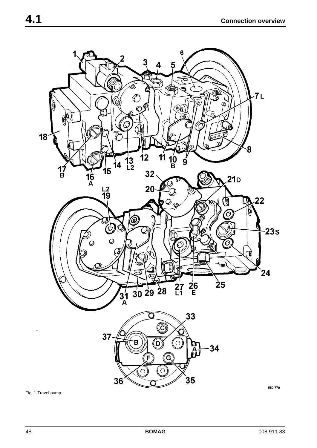
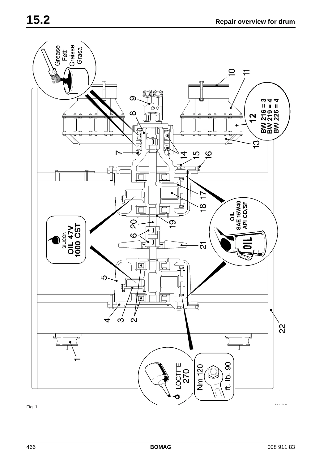
Reviews
There are no reviews yet.