★ TRUSTED BY 321,897+ PROFESSIONALS WORLDWIDE
🏒
Trusted Business
Verified & Licensed
πŸ›‘οΈ
Virus Free Files
100% Safe Downloads
πŸ”’
Secure Payment
SSL Protected
⚑
Instant Delivery
Available Immediately
Sale!

BOMAG BW 900-50 Tandem Vibratory Roller Service Manual 2019 – PDF Download

Original price was: $39.95.Current price is: $24.95.

Complete BOMAG BW 900-50 tandem vibratory roller Service Manual (doc 00840318, 2019). Covers engine, hydraulics, electrics, drums, articulated joint, troubleshooting, circuit and hydraulic diagrams for S/N 101 834 51 1001> and 861 834 07 2170>.

⚑
Instant PDF Download
Available immediately
πŸ’Ύ
Save to Your Device
Download & keep forever
πŸ›‘οΈ
Antivirus Scanned
100% virus-free
🌍
Trusted Worldwide
175,000+ customers

Description

BOMAG BW 900-50 Tandem Vibratory Roller Service Manual – 2019

This BOMAG BW 900-50 service manual is the workshop-level reference for the tandem vibratory roller, published under document number 00840318 with a 2019 date. It is written for BOMAG Customer Service and professionally trained personnel and supports deinstallation, dismantling, assembly, installation and repair of components and assembly groups. The manual applies to machines in the serial ranges S/N 101 834 51 1001> and S/N 861 834 07 2170>.

File Details

  • Manual type: Service Manual (workshop-level)
  • Brand: BOMAG / FAYAT GROUP
  • Model: BW 900-50 tandem vibratory roller
  • Document number: 00840318
  • Edition / date: 2019
  • Language: English
  • File format: PDF
  • Page count: 245 pages (including circuit and hydraulic diagram appendix)

Chapters Covered

  • 1 General information – Introduction, safety regulations, signage, maintenance and repair
  • 1.3 Maintenance and repair – Notes on repair (electrics, hydraulics, gaskets, bearings, screws and nuts, tightening torques), general maintenance notes
  • 2 Technical data – Machine data, additional technical data, terms and basis of calculation, fuels and lubricants, table of fuels and lubricants
  • 3 Overview of machine – General information, electric systems, hydraulic system, machine assemblies (engine, oscillating articulated joint, drums)
  • 4 Electric systems – Measuring technology, circuit diagrams, Telemecanique switch, jump starting, overview of electric system, control elements, central electrics, fuse assignment, engine oil pressure monitoring, proximity switches B08/B38
  • 5 Hydraulic system – Basic principles (open/closed circuits, swash plate pump, gear pumps and motors), overview of hydraulics, description of hydraulic components (travel pump PMVO 13S, travel motor TG405, steering valve), description of hydraulic circuits, tests and adjustments, flushing and bleeding
  • 6 Machine assemblies – Engine (Honda GX 630 overview, carburettor inspection, maintenance), oscillating articulated joint (removal, installation, repair), drum (vibratory front drum, rear drum, inspection and maintenance)
  • 7 Troubleshooting – Emergency procedures, electrical troubleshooting, hydraulic troubleshooting, engine troubleshooting
  • 8 Special tools – Hydraulic system tools, electrics tools, drum tools
  • 9 Index
  • Appendix – A.1 Circuit diagram 78, A.2 Hydraulic diagram 138

Complete PDF Bookmark Tree

Complete Bookmarks

The complete bookmarks in the β€œBOMAG BW 900-50 Tandem Vibratory Roller Service Manual 2019 – PDF Download” are as follows:

Table of contentsp. 3
1 ​​General information​​p. 6
1.1 ​​Introduction​​p. 7
1.2 ​​Safety regulations​​p. 9
1.2.1 ​​Signage​​p. 17
1.3 ​​Maintenance and repair​​p. 23
1.3.1 ​​Notes on repair​​p. 23
1.3.1.1 ​​General repair instructions​​p. 23
1.3.1.1.1 ​​Repair notes for electrics​​p. 23
1.3.1.1.2 ​​Repair notes for hydraulics​​p. 25
1.3.1.1.3 ​​Repair notes for gaskets and mating surfaces​​p. 26
1.3.1.1.4 ​​Repair notes for ball and roller bearings​​p. 28
1.3.1.1.5 ​​Feather keys and keyways​​p. 28
1.3.1.1.6 ​​Repair notes for cotter pins​​p. 29
1.3.1.1.7 ​​Repair notes for screws and nuts​​p. 29
1.3.1.1.8 ​​Strength classes, metric screws and nuts​​p. 29
1.3.1.1.9 ​​Identification of UNF-threads​​p. 31
1.3.1.2 ​​Tightening torques​​p. 31
1.3.2 ​​General notes on maintenance ​​p. 37
2 ​​Technical data​​p. 39
2.1 ​​Technical data​​p. 40
2.2 ​​Additional technical data​​p. 43
2.3 ​​Terms and basis of calculation​​p. 45
2.4 ​​Fuels and lubricants​​p. 46
2.5 ​​Table of fuels and lubricants​​p. 48
3 ​​Overview of machine​​p. 49
3.1 ​​General information​​p. 50
3.2 ​​Electric systems​​p. 51
3.3 ​​Hydraulic system​​p. 53
3.4 ​​Machine assemblies​​p. 54
3.4.1 ​​Engine​​p. 54
3.4.2 ​​Oscillating articulated joint​​p. 55
3.4.3 ​​Drums​​p. 57
4 ​​Electric systems​​p. 60
4.1 ​​Basic principles​​p. 61
4.1.1 ​​Measuring technology​​p. 61
4.1.2 ​​Understanding circuit diagrams​​p. 66
4.1.2.1 ​​Circuit diagrams​​p. 66
4.1.2.2 ​​Circuit symbols in E-Plan​​p. 73
4.1.2.3 ​​Identification of switch blocks​​p. 76
4.1.3 ​​Telemecanique switch​​p. 77
4.2 ​​Starting the engine with jump leads​​p. 79
4.3 ​​Overview of electric system​​p. 80
4.3.1 ​​Control elements​​p. 82
4.4 ​​Central electrics​​p. 84
4.5 ​​Fuse assignment​​p. 86
4.6 ​​Engine oil pressure monitoring​​p. 87
4.7 ​​Proximity switches, B08 and B38​​p. 88
4.8 ​​Inspection and maintenance work​​p. 90
4.8.1 ​​Maintenance Table​​p. 90
4.8.2 ​​Every 250 operating hours​​p. 90
4.8.2.1 ​​Battery service​​p. 90
5 ​​Hydraulic system​​p. 92
5.1 ​​Basic principles​​p. 94
5.1.1 ​​Open and closed hydraulic circuit​​p. 94
5.1.2 ​​Swash plate principle, pump​​p. 96
5.1.3 ​​External gear pumps​​p. 98
5.1.4 ​​Outer gear motors non-reversible​​p. 100
5.2 ​​Overview of hydraulics​​p. 101
5.3 ​​Description of hydraulic components​​p. 104
5.3.1 ​​Travel pump, PMVO 13S​​p. 104
5.3.2 ​​Travel motor TG405​​p. 107
5.3.3 ​​Steering valve​​p. 109
5.4 ​​Description of hydraulic circuits​​p. 111
5.4.1 ​​Travel circuit​​p. 111
5.4.2 ​​Vibration circuit​​p. 113
5.4.3 ​​Steering circuit​​p. 115
5.5 ​​Tests and adjustments​​p. 118
5.5.1 ​​Checking the rotation speeds​​p. 118
5.5.2 ​​Pressure tests in the travel circuit​​p. 120
5.5.3 ​​Adjusting the neutral positions of the travel pump​​p. 121
5.5.4 ​​Travel pump high pressure test​​p. 122
5.5.5 ​​Pressure tests in the vibration circuit​​p. 124
5.5.6 ​​Vibration pump high pressure test​​p. 125
5.5.7 ​​Checking the leakage rate of the vibration motor​​p. 127
5.5.8 ​​Pressure tests in the steering circuit​​p. 128
5.6 ​​Flushing and bleeding​​p. 130
5.6.1 ​​Flushing in general​​p. 130
5.6.2 ​​Flushing schematic for travel system​​p. 133
5.6.3 ​​Flushing the travel system​​p. 134
5.6.4 ​​Bleeding the travel circuit​​p. 138
5.7 ​​Inspection and maintenance work​​p. 140
5.7.1 ​​Maintenance Table​​p. 140
5.7.2 ​​Checks prior to start up​​p. 140
5.7.2.1 ​​Checking the hydraulic oil level ​​p. 140
5.7.2.2 ​​Checking the hydraulic oil filter element​​p. 141
5.7.3 ​​Every 2000 operating hours​​p. 141
5.7.3.1 ​​Changing the hydraulic oil​​p. 141
5.7.3.2 ​​Change the hydraulic oil filter​​p. 143
6 ​​Machine assemblies​​p. 145
6.1 ​​Engine​​p. 147
6.1.1 ​​Engine overview​​p. 147
6.1.2 ​​Carburettor inspection​​p. 149
6.1.3 ​​Inspection and maintenance work​​p. 151
6.1.3.1 ​​Maintenance Table​​p. 151
6.1.3.2 ​​Every 10 operating hours​​p. 151
6.1.3.2.1 ​​Checking the engine oil level​​p. 151
6.1.3.2.2 ​​Cleaning the cooling air intake openings​​p. 152
6.1.3.3 ​​Every 125 operating hours​​p. 153
6.1.3.3.1 ​​Check, clean the air filter, replace if necessary​​p. 153
6.1.3.3.2 ​​Clean, check the spark plugs, replace if necessary​​p. 154
6.1.3.3.3 ​​Changing engine oil and oil filter​​p. 156
6.1.3.4 ​​Every 250 operating hours​​p. 157
6.1.3.4.1 ​​Change the fuel pre-filter​​p. 157
6.1.3.4.2 ​​Checking, adjusting the valve clearance​​p. 158
6.1.3.4.3 ​​Check, adjust the idle speed​​p. 159
6.1.3.5 ​​Every 2000 operating hours​​p. 159
6.1.3.5.1 ​​Checking fuel lines and clamps​​p. 159
6.1.3.6 ​​As required​​p. 160
6.1.3.6.1 ​​Engine conservation​​p. 160
6.2 ​​Oscillating articulated joint​​p. 162
6.2.1 ​​Repair overview for oscillating articulated joint​​p. 163
6.2.2 ​​Removing and installing the oscillating articulated joint​​p. 165
6.2.3 ​​Repairing the oscillating articulated joint​​p. 166
6.3 ​​Drum​​p. 172
6.3.1 ​​Vibratory drum, front​​p. 172
6.3.1.1 ​​Repair overview of vibratory drum​​p. 173
6.3.1.2 ​​Removing and installing the vibratory drum​​p. 174
6.3.1.3 ​​Dismantling the vibratory drum​​p. 177
6.3.1.4 ​​Assembling the vibratory drum​​p. 182
6.3.2 ​​Rear drum​​p. 188
6.3.2.1 ​​Repair overview of rear drum​​p. 189
6.3.2.2 ​​Removing and installing the rear drum​​p. 190
6.3.2.3 ​​Dismantling the rear drum​​p. 191
6.3.2.4 ​​Assembling the rear drum​​p. 194
6.3.3 ​​Inspection and maintenance work​​p. 196
6.3.3.1 ​​Maintenance Table​​p. 196
6.3.3.2 ​​Every 10 operating hours​​p. 196
6.3.3.2.1 ​​Cleaning the scrapers​​p. 196
6.3.3.3 ​​Every 125 operating hours​​p. 197
6.3.3.3.1 ​​Lubricating the rear drum bearings​​p. 197
7 ​​Troubleshooting​​p. 198
7.1 ​​Preliminary remarks​​p. 199
7.2 ​​Emergency procedures​​p. 200
7.2.1 ​​Actuating the emergency stop switch​​p. 200
7.2.2 ​​Towing​​p. 200
7.3 ​​Troubleshooting, electrical systems​​p. 202
7.3.1 ​​Preliminary remarks​​p. 202
7.3.2 ​​Fuse assignment​​p. 205
7.3.3 ​​Starting the engine with jump leads​​p. 206
7.4 ​​Trouble shooting, hydraulics​​p. 207
7.4.1 ​​Preliminary remarks​​p. 207
7.4.2 ​​Insufficient hydraulic power​​p. 208
7.4.3 ​​Troubleshooting axial piston pumps​​p. 211
7.5 ​​Trouble shooting, diesel engine​​p. 214
7.5.1 ​​Starting the engine with jump leads​​p. 214
7.5.2 ​​Engine problems ​​p. 214
8 ​​Special tools​​p. 216
8.1 ​​Special tools for hydraulic system​​p. 217
8.1.1 ​​Special tools, tests and adjustments​​p. 217
8.1.2 ​​Special tools for flushing​​p. 219
8.2 ​​Special tools, electrics​​p. 220
8.3 ​​Special tools for drum​​p. 221
9 ​​Index​​p. 222
Appendixp. 225
A Circuit diagramsp. 227
A.1 Circuit diagram 78p. 227
A.2 Hydraulic diagram 138p. 237

Across those chapters the manual delivers the complete servicing workflow for the BW 900-50: it opens with safety regulations and shop practice, then lays out the machine’s technical data and fuel/lubricant requirements, then moves into system-level chapters for electrics, hydraulics and the drum assemblies. The hydraulic section alone walks through the travel pump, travel motor, steering valve, travel circuit, vibration circuit and steering circuit, then supplies step-by-step pressure tests, neutral-position adjustment, flushing procedures and bleeding of the travel circuit. The machine assemblies chapter covers the Honda GX 630 engine, the oscillating articulated joint, and full disassembly and reassembly of both the front vibratory drum and the rear drum. The troubleshooting chapter groups faults by system, and the appendix provides the wiring and hydraulic diagrams needed to trace them.

Coverage and Serial Numbers

This BOMAG BW 900-50 tandem vibratory roller service manual is written to cover machines in the serial number ranges S/N 101 834 51 1001> and S/N 861 834 07 2170>. The engine is the air-cooled Honda GX 630, a four-stroke two-cylinder unit rated 14.9 kW at 3300 min-1, and the manual addresses it both as a service item (oil, oil filter, air filter, spark plugs, valve clearance, idle speed, fuel pre-filter, fuel lines) and as a troubleshooting subject.

Systems Covered in Depth

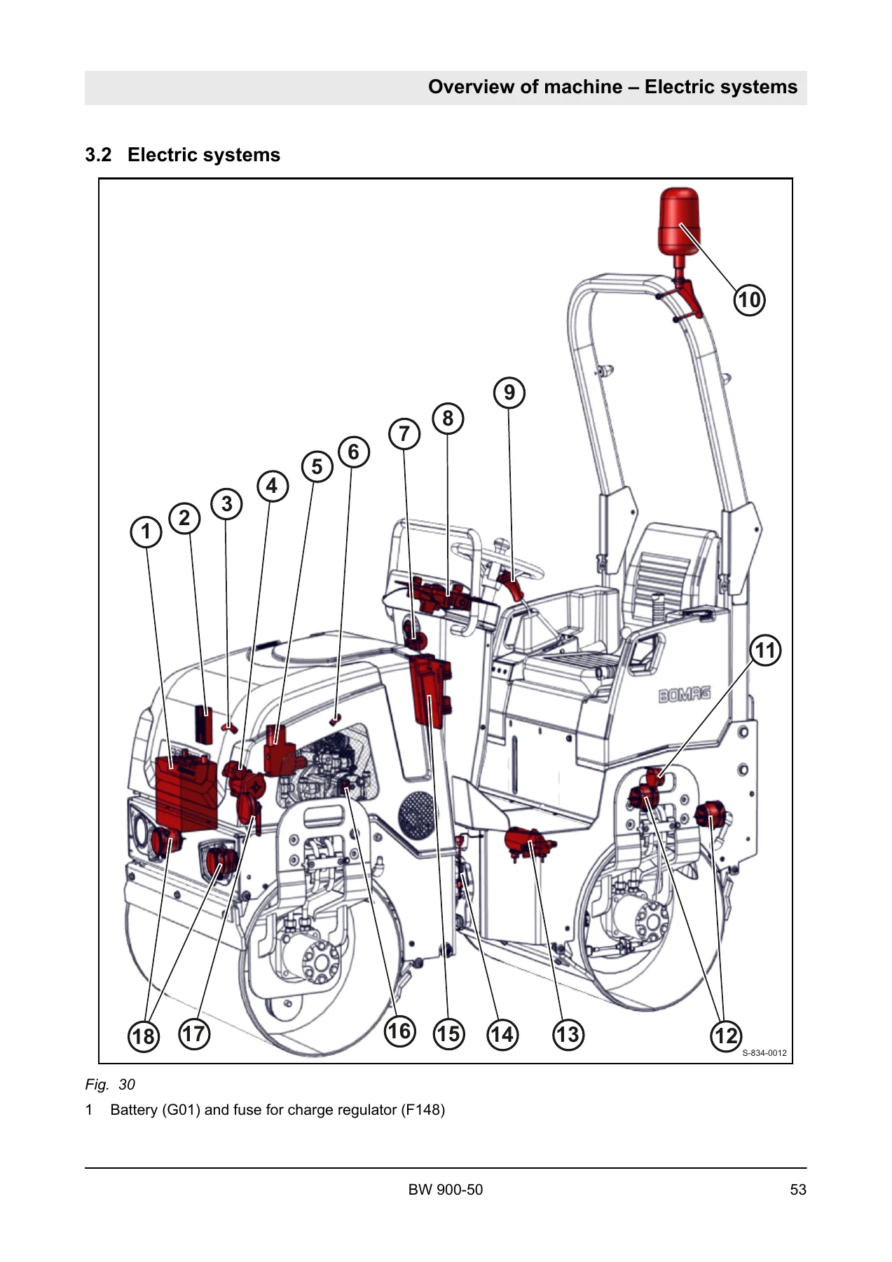
The BW 900-50 repair manual concentrates its technical detail on the systems that fail most often on a tandem roller. Electrical coverage includes the measuring technology you need before touching the harness, how to read the BOMAG circuit diagrams, the Telemecanique switch, the central electrics board with its relays (K04 stepping relay for vibration, K05/K31 start current, K26 reverse alarm, K29 vibration, K23 spraying pump, K96 engine oil pressure, K69 engine shut-down, K136 seat contact timer), fuse assignment, engine oil pressure monitoring, and the B08/B38 proximity switches on the travel lever. Hydraulic coverage is the largest single block: the PMVO 13S travel pump, the TG405 gerotor travel motor, the steering valve, the open vibration circuit, the closed travel circuit, and the steering circuit, followed by rotation-speed checks, travel-circuit pressure tests, travel-pump high-pressure test, vibration-circuit pressure tests, vibration-motor leakage test, steering-circuit pressure tests, flushing of the travel system and bleeding of the travel circuit.

IMAGES PREVIEW

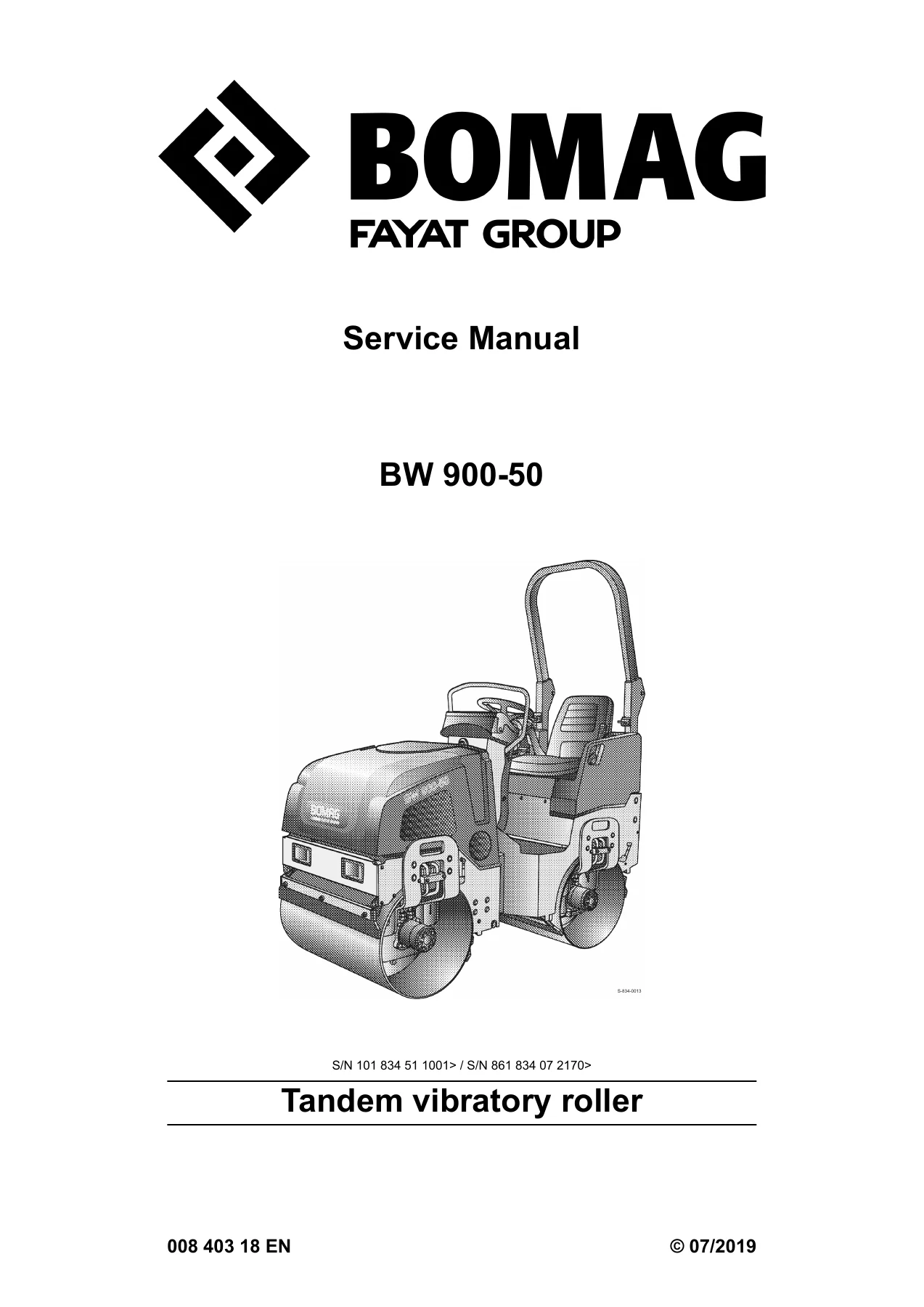
BOMAG BW 900-50 Tandem Vibratory Roller Service Manual 2019 - PDF Download β€” PDF page 1 preview
BOMAG BW 900-50 Tandem Vibratory Roller Service Manual 2019 - PDF Download β€” PDF page 51 preview
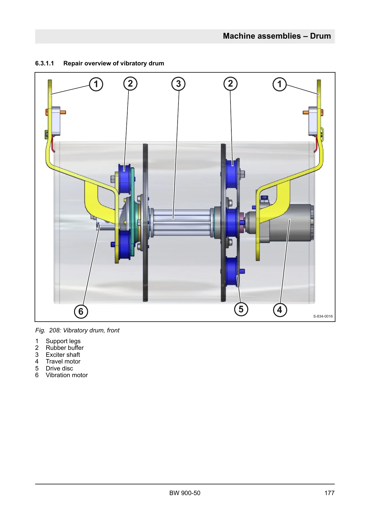
BOMAG BW 900-50 Tandem Vibratory Roller Service Manual 2019 - PDF Download β€” PDF page 173 preview

Specifications and Service Data

Alongside the procedures, this BOMAG BW 900-50 service manual PDF contains the numbers a technician needs at the bench: tightening torques for metric, UNC and UNF fasteners, hydraulic fittings in L and S series, wheel nuts and anti-seizure-paste joints; strength-class identification for screws and nuts; operating weight and CECE weight; travel and working speeds; gradeability; drum vibration frequency and amplitude; centrifugal force; engine oil, hydraulic oil and fuel capacities; and the engine valve clearance and spark plug gap values. The engine oil change interval, hydraulic oil change interval and filter service intervals are all listed with their operating-hour triggers.

Who This Manual Is For

This BW 900-50 workshop manual suits the workshop technician servicing a fleet machine, the independent repair shop taking on a BOMAG tandem roller for the first time, and the owner-operator who wants the factory procedure and torque values before opening a hydraulic circuit. It assumes access to standard hand tools, a hydraulic test case with 60 bar and 600 bar gauges, and a filling and filtering unit for the flushing procedures. The document does not cover operator-level daily checks beyond the maintenance tables – those belong in the operating and maintenance instructions.

With the BOMAG BW 900-50 Tandem Vibratory Roller Service Manual on hand you can diagnose an electrical fault against the printed circuit diagram, test the travel circuit pressures to specification, flush the hydrostatic system after a component change, bleed the travel circuit correctly, adjust the neutral position of the travel pump, set valve clearance on the Honda GX 630, and rebuild the oscillating articulated joint or a drum using the illustrated step-by-step procedures. Getting the procedure and the torque value right the first time is the difference between a machine that returns to the job and a comeback repair on a hydrostatic system that is unforgiving of contamination. The manual is delivered as an instant PDF download – no shipping, no waiting, viewable on any device and printable for the workshop shelf.
Reviews

There are no reviews yet.

Be the first to review “BOMAG BW 900-50 Tandem Vibratory Roller Service Manual 2019 – PDF Download”

What Our Customers Say

β˜…β˜…β˜…β˜…β˜… Live reviews from customers
Loading customer reviews...
0
    0
    Your Cart
    Your cart is emptyReturn to Shop
    πŸ›’
    Recently Purchased
    πŸ•’ verified order