
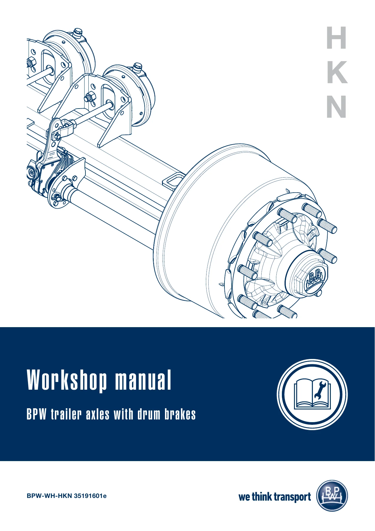
BPW H K N Trailer Axles with Drum Brakes Workshop Manual – ECO Plus 3, ECO Plus 2, ECO Plus, ECO & Conventional Hub Bearing Repair PDF
Original price was: $50.95.$34.95Current price is: $34.95.
Complete BPW workshop manual for H, K and N trailer axles with drum brakes and S-camshaft SN 420 / SN 360 / SN 300. Covers ECO Plus 3, ECO Plus 2, ECO Plus, ECO and conventional wheel hub bearings – brake lining changes, hub dismantling, camshaft, slack adjusters, ABS, brake cylinders and ECOMETER. 136-page PDF.
Description
BPW H, K and N Trailer Axles with Drum Brakes – Workshop Manual
This is the full BPW workshop manual for trailer axles with drum brakes running the S-camshaft SN 420, SN 360 and SN 300 brake platforms, in the ECO Plus 3, ECO Plus 2, ECO Plus, ECO and conventional wheel hub bearing configurations. It is the working reference used for brake relining, hub unit overhaul, camshaft and slack adjuster service, ABS setup and ECOMETER fitting on BPW H, K and N series axles. Every procedure is written around BPW’s own torque values, grease specifications and part numbers, so the steps in the PDF are the steps you actually carry out in the workshop.
File Details
- Manual type: Workshop manual
- Brand: BPW Bergische Achsen KG
- Product line: BPW trailer axles with drum brakes (H, K and N series)
- Document number: BPW-WH-HKN 35191601e
- Language: English
- Page count: 136 pages
- File format: PDF
Chapters Covered
- 1. Product identification
- 2. Exploded view / name
- 3. Safety regulations, safety information
- 4. Tightening torques
- 5. Special tools
- 6. Lubrication and maintenance work
- 7. Changing the brake lining
- 8. Dismantling and assembling the hub unit
- 9. ABS / ABV
- 10. Brake back plates for Brake – ECO Drum
- 11. Brake camshaft
- 12. Manual slack adjuster GSK
- 13. Automatic slack adjuster ECO-Master
- 14. Brake wear sensing
- 15. Brake cylinder
- 16. Digital ECOMETER
Product Identification
Every axle type plate BPW has fitted over the years is shown and decoded here – the riveted plate used up to model year 1999, the adhesive plate from 2000, the barcoded version from 2006 and the ECE-certificate plate from 2011. The chapter explains where the axle type, BPW code number, date and serial number, brake type, certificate type and test report number sit on each plate, and how to read the ID1 axle code, ID2 brake code, ID3 tested brake axle load and ID4 basic test report number. If you have ever had to order a brake kit against an unidentified stub axle, this is the chapter that saves the phone call.
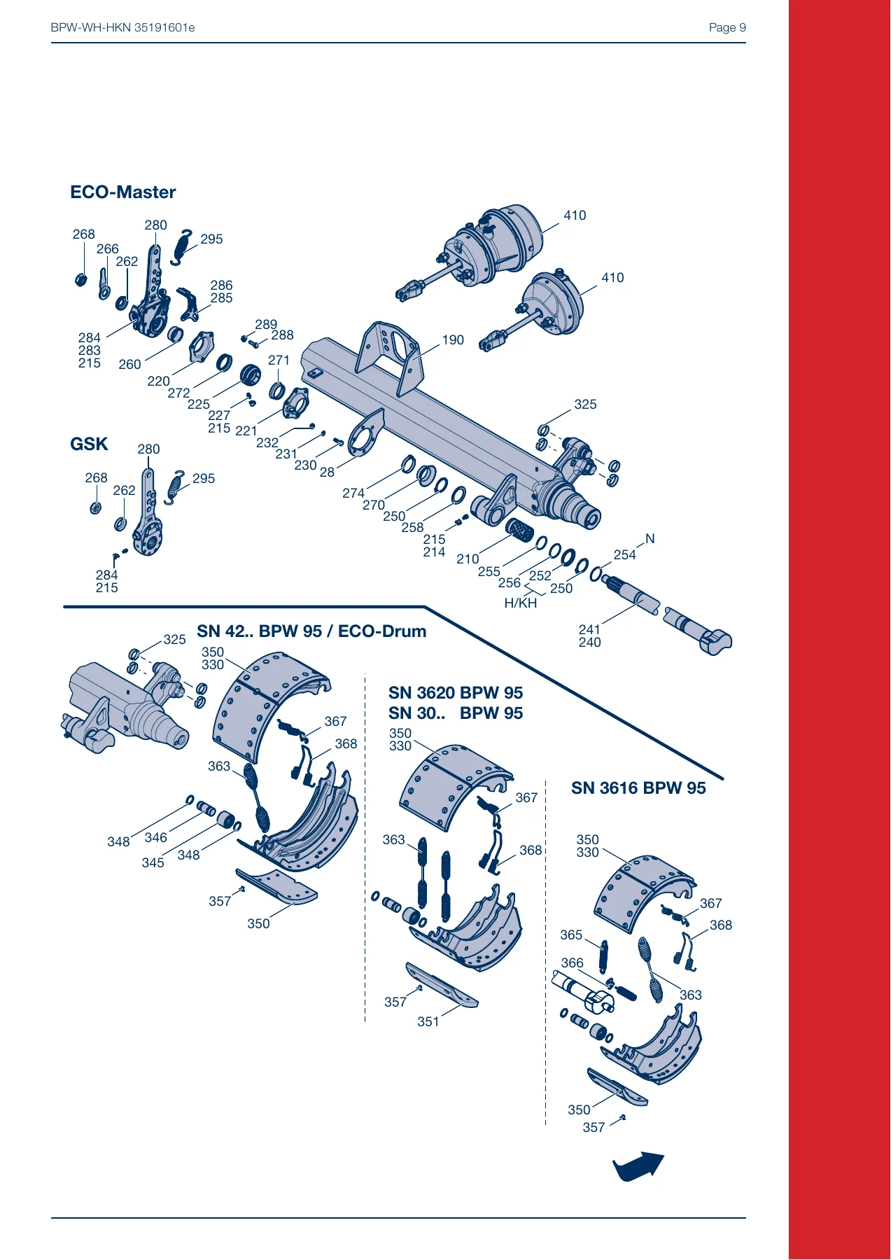
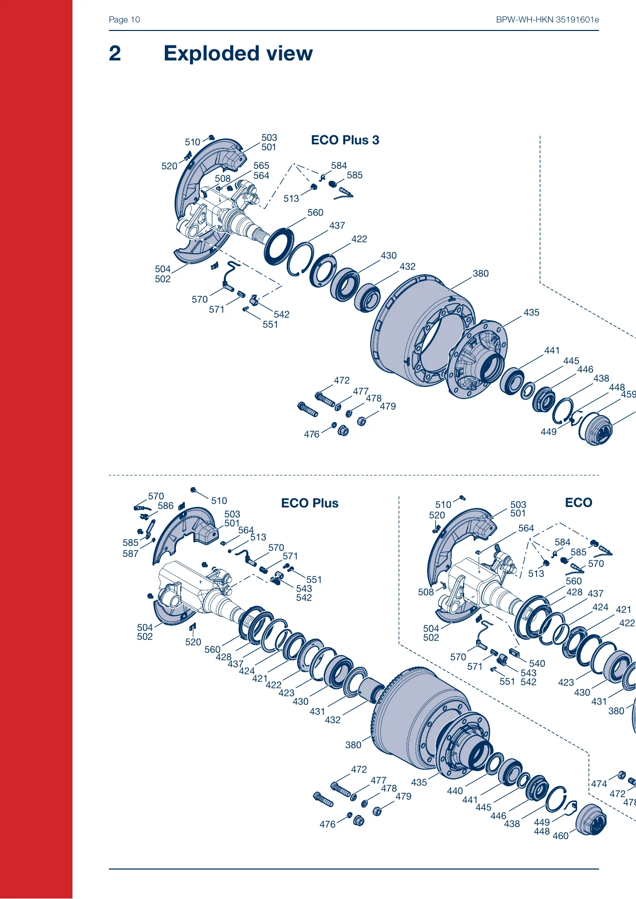
Exploded Views and Part Names
The full assembly is broken down across folding exploded drawings for the ECO-Master and GSK slack adjusters, the SN 42.. / SN 3620 / SN 30.. / SN 3616 brake platforms in BPW 95 and ECO-Drum form, and for the ECO Plus 3, ECO Plus 2, ECO Plus, ECO and conventional hub units. Each item number in the drawing is named in the accompanying parts list – bushings, O-rings, sealing rings, rollers, brake shoe and lining assemblies, return springs, hub caps, axle nuts, exciter rings, ABS sensors, dust covers, wheel studs, lock nuts and wheel nuts. Use it as a parts locator when you are rebuilding a brake or hub unit from scratch.
Safety Regulations and Tightening Torques
The safety chapter sets out the rules for brake work on commercial vehicles – trained brake personnel, depressurised airlines, vehicle immobilisation, brake dust extraction between 40 and 50 m3/h, no compressed air cleaning, and the requirement to renew return springs whenever linings are changed. The torque chapter then gives the actual figures you tighten to: hub caps, axle nuts and axle bolts by axle load and hub cap shape, wheel nuts by stud alignment and spigot alignment, Trilex and Japan connection tables, slack adjuster lock nuts, brake cylinder attachment nuts, compressed air connections, spring brake hold-off bolts, cover plate locking bolts and sensor holder bolts.
Special Tools
Every BPW tool referenced by the procedures is listed with its BPW code number, spanner size and application photo – sockets and ring spanners for hub caps, sockets for axle nuts, hub pullers for each axle size, the taper roller bearing puller for 6.5 to 14 tonne axles, driving mandrel sets for camshaft and brake pin bushes, press tools for roller bearing outer rings and ECO hub seal bearing rings, exciter ring assembly aids, roller bearing grease applicators, the ECO Plus 2 puller and the slack adjuster puller. If a job in this manual needs a tool, the number is here.
Lubrication and Maintenance Work
This is the largest chapter and covers the whole service schedule. Greasing intervals are laid out on-road, off-road and outside Europe for the inner and outer brake camshaft bearings, the manual slack adjuster and the ECO-Master automatic slack adjuster, with the exact ECO-Liplus grease quantity per taper roller bearing (170 g inner / 120 g outer on ECO Plus 3 and ECO Plus 2, load-dependent tables for ECO Plus, ECO and conventional hub bearings). The hub bearing grease-change procedures for ECO Plus 3, ECO Plus 2, ECO Plus, ECO and conventional hub bearings are each given as a step-by-step sequence with an illustration for every stage. Maintenance items follow: wheel nut tightening, brake play check with manual slack adjusters, tyre wear, brake lining thickness minimums (5 mm on SN 420 / SN 360, 7 mm on SN 300), brake drum cracks and internal diameter with wear and skimming limits, cap seating, visual inspection of components and welds, ECO-Master operation check, and wheel hub bearing play adjustment for every hub variant.
Changing the Brake Lining
The whole relining job is documented: removing the wheel hub / brake drum unit on ECO Plus 3, ECO Plus 2, ECO Plus, ECO and conventional bearings, resetting the slack adjuster, lifting the brake shoes, replacing the linings with the riveting order, riveting force of 21,000 N and semi-tubular rivet spec, riveting inspection with the three failure patterns, roller and bearing bolt renewal, return spring routing for each series (H/SN 420, N/SN 300, K/SN 3620, K/SN 3616), positioning springs, sensor handling, and refitting the complete wheel hub brake drum unit with the correct torques and axle nut locking method for each hub design. Also included is the conversion of older brakes to the split roller BPW 95 brake with the parts breakdown for the new shoe and spring set.
Dismantling and Assembling the Hub Unit
Dedicated overhauls for each hub family, step by step with numbered illustrations – ECO Plus 3, ECO Plus 2, ECO Plus, ECO and conventional. Each covers removal of the circlips and axle nut, pulling the roller bearings, exciter ring handling (pressed, clipped with lateral bracket, bayonet lock and shrink-fit variants), grease cartridge removal and refilling without air pockets, driving out the bearing outer races with the correct BPW insertion tools, refitting the inner and outer tapered roller bearings, seal and O-ring placement, wheel stud installation with the anti-rotation lock, and re-fitting the axle nut with the locking key and hooked spring ring. The chapter notes clearly that opening an ECO Plus 3 or ECO Plus 2 unit during the warranty period invalidates the ECO Plus warranty.
ABS / ABV and Brake Wear Sensing
The ABS section covers the sensor, clamping bush, exciter ring renewal for pressed, clipped, bayonet and shrink-fit types, correct sensor force (100 to 200 N) and the precaution of pressing the sensor up to the endstop before fitting the hub so the exciter ring pushes it back to position. Brake wear sensing explains how the sensor tracks the slack adjuster, the 90-degree wear limit that triggers the SERVICE signal on the Brake Monitor, the difference in lining thickness markers (18, 19 and 20 mm), installation on the opposite side to the control lever, and how the sensor is reset rather than replaced at every lining change.
Brake Camshaft, Slack Adjusters and Brake Cylinder
Camshaft overhaul covers nut and wear indicator removal, the disc, the push-on bush or retaining ring and sealing ring on pre- and post-October 2000 shafts, spherical bearing support plates, spherical bearing and sealing ring wear (0.8 mm bearing play limit), bush renewal with the 7.2 + 0.5 mm setback and the ring groove facing the grease nipple, O-ring and seal placement for series H / K and series N, and the free-rotation check after assembly. The GSK manual slack adjuster and the ECO-Master automatic slack adjuster each get their own fitting and adjustment procedure, including the base setting of the ECO-Master control lever lug against the control point. The brake cylinder chapter covers diaphragm cylinder installation with the 227 mm push rod reference, minimum 40 mm clearance, 90-degree push rod to slack adjuster angle at half stroke, drain hole position, and the complete spring brake cylinder wind-off bolt procedure with the compressed air connection at 1.2 bar.
IMAGES PREVIEW
Reviews
There are no reviews yet.