Brother MFC8500 FAX8360P Service Manual PDF (2002) DOWNLOAD
Original price was: $95.00.$18.95Current price is: $18.95.
Download the official Brother facsimile equipment service manual PDF for MFC8500, FAX4100, FAX4750e, FAX5750e, MFC9660, and FAX8360P models, featuring Brother fax machine repair instructions, disassembly guide for Brother MFC series, troubleshooting Brother fax errors, and maintenance mode for Brother laser fax. This 239-page resource includes theory of operation, error codes, firmware switches, and circuit diagrams for efficient repairs.
Description
Brother MFC8500 FAX8360P Service Manual PDF (2002) DOWNLOAD
Description
The Brother Facsimile Equipment Service Manual is a crucial technical guide for service technicians and repair professionals handling Brother’s MFC and FAX series machines. This comprehensive Brother fax machine service manual PDF offers detailed Brother fax machine repair instructions, from general specifications to advanced troubleshooting Brother fax errors, ensuring quick diagnostics and fixes. Covering installation, theory of operation, disassembly guide for Brother MFC series, lubrication, maintenance mode for Brother laser fax, and error indication, it helps maintain optimal performance and resolve issues like paper jams, print quality problems, and communication errors.
For easy navigation, the table of contents is categorized below:
Chapter I: General Description (Page 6)
- Equipment Outline
- 1.1 External Appearance and Weight
- 1.2 Components
- Specifications
Chapter II: Installation (Page 21)
- Installing the Update Data to the Facsimile Machine
- Setting ID Codes to Facsimile Machines
Chapter III: Theory of Operation (Page 26)
- Overview
- Mechanisms
- 2.1 Scanner Mechanism
- 2.1.1 Document Feeding and Ejecting Mechanism
- 2.1.2 Scanner
- 2.2 Laser Printing Mechanism
- 2.2.1 Paper Pick-up and Registration Mechanism
- 2.2.2 Print Process Mechanism
- (1) Charging Process
- (2) Exposing Process
- (3) Developing Process
- (4) Transferring Process
- 2.2.3 Heat-fixing Mechanism
- 2.2.4 Paper Ejecting Mechanism
- 2.3 Sensors and Actuators
- Control Electronics
Chapter IV: Disassembly/Reassembly and Lubrication (Page 40)
- Safety Precautions
- Preparation
- How to Access the Object Component
- Disassembly Order Flow
- 1.1 Rear Cover
- 1.2 Access Plates R and F
- 1.3 Control Panel ASSY
- 1.4 Panel Rear Cover and Control Panel
- 1.5 Document Feed Roller ASSY, Document Ejection Roller ASSY, and Pinch Rollers
- 1.6 CIS Unit
- 1.7 Scanner Frame ASSY (Scanner Motor, Scanner Drive Unit, Document Take-in Roller, Separation Roller, Pressure Rollers, and Control Panel Locks)
- 1.8 Top Cover (Exit Roller, Speaker, and Document Guides)
- 1.9 Handset Mount and Hook Switch PCB (for models equipped with a handset) Side Cover (for models without handset)
- 1.10 Paper Sub Tray
- 1.11 VC Cover, VC Bracket, and VC Connector PCB (for models supporting video capture)
- 1.12 Front Cover Front Sub Cover (for models not supporting video capture)
- 1.13 Outer Chute and Paper Pinch Rollers
- 1.14 Main Cover
- 1.15 Switch Cover
- 1.16 Laser Unit
- 1.17 Heat-fixing Unit and FU Lamp
- [Disassembling the heat-fixing unit]
- 1.18 Fan
- 1.19 Drive Gear ASSY and Main Motor ASSY
- 1.20 NCU Shield and NCU PCB
- 1.21 Bottom Plate, Main PCB and Bottom Insulation Film
- 1.22 Low-voltage Power Supply PCB and Power Inlet
- 1.23 Paper Feed Motor ASSY
- 1.24 Clutch Levers R and F, Solenoid Release Lever, Clutch Lever Springs, Registration Clutch Lever, and Solenoid
- 1.25 Toner Sensor PCB and Toner LED PCB
- 1.26 Gears and Paper Pick-up Roller
- 1.27 Paper Feed Solenoid ASSY, Solenoid Release Spring, and Clutch Lever L
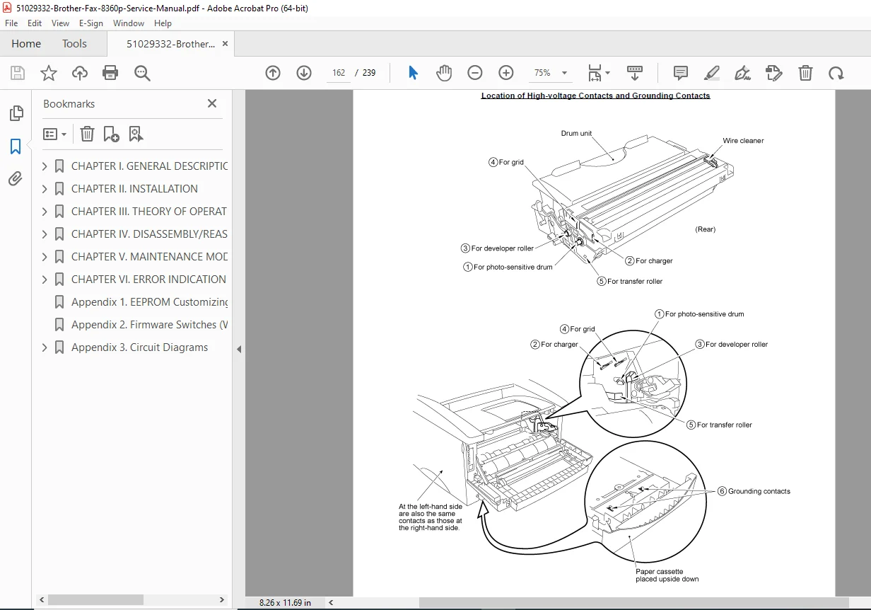
- 1.28 Cleaning of High-voltage Contacts and Grounding Contacts (Periodical maintenance mode)
- Lubrication
Chapter V: Maintenance Mode (Page 112)
- Entry into the Maintenance Mode
- List of Maintenance-Mode Functions
- Detailed Description of Maintenance-Mode Functions
- 3.1 EEPROM Parameter Initialization
- 3.2 Printout of Scanning Compensation Data
- 3.3 ADF Performance Test
- 3.4 Test Pattern 1
- 3.5 Firmware Switch Setting and Printout
- 3.6 Operational Check of LCD
- 3.7 Operational Check of Control Panel PCB
- 3.8 Receiver Volume Adjustment (applicable to the American version only)
- 3.9 Sensor Operational Check
- 3.10 Fine Adjustment of Scanning Start/End Position
- 3.11 CIS Scanner Area Setting
- 3.12 EEPROM Customizing
- 3.13 Display of the Equipment’s Log Information
- 3.14 Equipment Error Code Indication
- 3.15 Output of Transmission Log to the Telephone Line
- 3.16 Cancellation of the Memory Security Mode (applicable to the European version only)
Chapter VI: Error Indication and Troubleshooting (Page 134)
- Error Indication
- 1.1 Equipment Errors
- [1] Error Messages on the LCD
- [2] Error Codes Shown in the “MACHINE ERROR X X” Message
- 1.2 Communications Errors
- Troubleshooting
- 2.1 Introduction
- 2.2 Precautions
- 2.3 Checking Prior to Troubleshooting
- 2.4 Troubleshooting Procedures
- [1] Control Panel Related
- [2] Telephone Related
- [3] Communications Related
- [4] Paper/Document Feeding Related
- [5] Print-Image Related
- Location of High-voltage Contacts and Grounding Contacts
Appendices
- Appendix 1: EEPROM Customizing Codes
- Appendix 2: Firmware Switches (WSW)
- Appendix 3: Circuit Diagrams
- Appendix 4: Toner Cartridge Weight
This disassembly guide for Brother MFC series includes diagrams, error code explanations, and practical troubleshooting Brother fax errors tips for field repairs.
File Details:
- Manual Name: Brother Facsimile Equipment Service Manual
- Models Covered: MFC8500, FAX4100, FAX4750e, FAX5750e, MFC9660, FAX8360P
- Year: 2002
- Manual PDF Quality: High-quality scanned document with clear text and images
- Number of Pages: 239
Equip yourself with this essential Brother fax machine service manual PDF to diagnose and repair issues efficiently – download now for immediate access and keep your equipment running smoothly!