Trusted Business
Verified & Licensed
Virus Free Files
100% Safe Downloads
Secure Payment
SSL Protected
Instant Delivery
Available Immediately
BT Forklift BT PPH 1600MX BT PPS 1600MXD BT PPS 1200MXF Service Manual – PDF
$27.95
BT Forklift BT PPH 1600MX BT PPS 1600MXD BT PPS 1200MXF BT PPS 1000MX BT PPS 1200MX BT PPS 1200MXS Service Manual – PDF DOWNLOAD
Instant PDF Download
Available immediately
Save to Your Device
Download & keep forever
Antivirus Scanned
100% virus-free
Trusted Worldwide
175,000+ customers
Description
BT Forklift BT PPH 1600MX BT PPS 1600MXD BT PPS 1200MXF BT PPS 1000MX BT PPS 1200MX BT PPS 1200MXS Service Manual – PDF DOWNLOAD
FILE DETAILS:
BT Forklift BT PPH 1600MX BT PPS 1600MXD BT PPS 1200MXF BT PPS 1000MX BT PPS 1200MX BT PPS 1200MXS Service Manual – PDF DOWNLOAD
Language : English
Pages : 220
Downloadable : Yes
File Type : PDF
IMAGES PREVIEW OF THE MANUAL:
TABLE OF CONTENTS:
BT Forklift BT PPH 1600MX BT PPS 1600MXD BT PPS 1200MXF BT PPS 1000MX BT PPS 1200MX BT PPS 1200MXS Service Manual – PDF DOWNLOAD
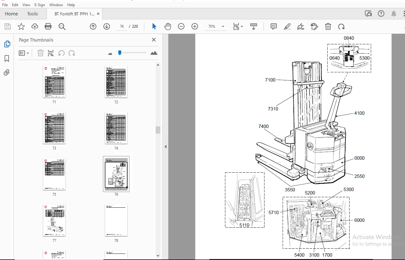
Contents Master Service Manual (MSM).......................................................  3
	1 Document list........................................................................  3
Introduction to BT’s Service Manual........................................................  5
Contents, M................................................................................  7
	1 Truck information....................................................................  7
Operator’s manual..........................................................................  9
	1 General..............................................................................  9
		1.1 Issued operator’s manuals......................................................  9
General product information................................................................ 11
	1 Presentation of the truck............................................................ 11
		1.1 Intended application of the truck.............................................. 11
		1.2 Forbidden application of the truck............................................. 12
		1.3 Truck data..................................................................... 12
		1.4 Truck dimensions............................................................... 14
		1.5 Identification plate........................................................... 16
		1.6 Capacity plate................................................................. 17
		1.7 Load distribution plate........................................................ 17
		1.8 Modification plate............................................................. 18
	2 Main components...................................................................... 19
	3 Warning and information plates and symbols........................................... 22
General product information................................................................ 23
	1 Presentation of the truck............................................................ 23
		1.1 Intended use of the truck...................................................... 23
		1.2 Forbidden use of the truck..................................................... 24
		1.3 Truck data..................................................................... 24
		1.4 Truck dimensions............................................................... 26
		1.5 Type plate..................................................................... 28
		1.6 Capacity plate................................................................. 29
		1.7 Modification plate............................................................. 29
	2 Main components...................................................................... 30
	3 Warning and information plates....................................................... 32
General product information................................................................ 33
	1 Presentation of the BT pedestrian stackers........................................... 33
		1.1 Intended application of the truck.............................................. 33
		1.2 Forbidden application of the truck............................................. 34
		1.3 Truck data..................................................................... 34
		1.4 Truck dimensions PPS 1000MX.................................................... 35
		1.5 Truck dimensions PPS 1200MX.................................................... 36
		1.6 Truck dimensions PPS 1200MXS................................................... 37
		1.7 Type plate..................................................................... 38
		1.8 Capacity plate................................................................. 38
		1.9 Modification plate............................................................. 39
	2 Main components...................................................................... 40
	3 Warning and information signs........................................................ 42
Technical data............................................................................. 43
Technical data............................................................................. 47
Ordering Spare Parts....................................................................... 51
Quality Parts.............................................................................. 53
	1 Issued Quality Parts................................................................. 53
Recommended Spare Parts (RSP).............................................................. 55
	1 Issued RSP........................................................................... 55
Contents, P................................................................................ 57
	1 Preventive Maintenance............................................................... 57
Introduction, maintenance.................................................................. 59
	1 Safety regulations with maintenance work............................................. 59
	2 Cleaning and washing................................................................. 61
		2.1 External cleaning.............................................................. 61
		2.2 Cleaning the motor compartment................................................. 61
		2.3 Electrical components.......................................................... 62
	3 Safe lifting......................................................................... 62
Preventive maintenance..................................................................... 63
	1 Maintenance schedule................................................................. 63
	2 Lubrication chart.................................................................... 69
Preventive maintenance..................................................................... 71
	1 Maintenance schedule................................................................. 71
	2 Lubrication chart.................................................................... 77
Oil and grease specification............................................................... 79
	1 Approved oil’s and grease for PPS 1000/1200MX and PPS 1200MXS........................ 79
Contents, S................................................................................ 81
	1 Service instructions................................................................. 81
Support arm chassis........................................................................ 83
	1 General.............................................................................. 83
	2 Main components...................................................................... 84
	3 Maintenance.......................................................................... 84
	4 Adjustment of the support arm width.................................................. 85
	5 Exchange of support arms............................................................. 86
Drive motor................................................................................ 87
	1 General.............................................................................. 87
		1.1 Mechanical construction........................................................ 88
		1.2 Special tools.................................................................. 89
	2 Removal/Refitting.................................................................... 89
		2.1 Removing the motor from the truck.............................................. 89
		2.2 Re-assembling.................................................................. 90
	3 Service/Repairs...................................................................... 91
		3.1 Cleaning....................................................................... 91
		3.2 Dismantling.................................................................... 92
		3.3 Re-assembling.................................................................. 93
		3.4 Armature bearings.............................................................. 94
			3.4.1 Changing the drive end bearing........................................... 94
			3.4.2 Changing the commutator end bearing...................................... 94
		3.5 Carbon brushes and brush holder................................................ 95
			3.5.1 Changing carbon brushes.................................................. 95
		3.6 Commutator..................................................................... 95
			3.6.1 Machining the commutator................................................. 95
	4 Storage/Transport.................................................................... 96
		4.1 Storage........................................................................ 97
	5 Data................................................................................. 98
Driving gear............................................................................... 99
	1 General technical description........................................................ 99
		1.1 Technical data.................................................................100
		1.2 Gear components................................................................101
		1.3 Special tools..................................................................102
	2 Removing the gear from the truck.....................................................103
	3 Change of seal on the drive shaft....................................................104
	4 Reconditioning of the gear...........................................................106
Mechanical brakes..........................................................................111
	1 General..............................................................................111
	2 Function.............................................................................112
		2.1 Releasing the brakes...........................................................112
		2.2 Braking........................................................................112
	3 Maintenance..........................................................................113
Electrical system..........................................................................115
	1 Electrical panel, components.........................................................115
	2 List of symbols and electrical diagrams..............................................116
		2.1 List of symbols................................................................116
		2.2 Electrical diagram 1(3)........................................................118
		2.3 Electrical diagram 2(3)........................................................119
		2.4 Electrical diagram 3(3)........................................................120
	3 Description of function..............................................................121
		3.1 General........................................................................121
		3.2 Adjustable settings............................................................121
		3.3 Description....................................................................121
		3.4 Ignition lock S17 in the ON position...........................................122
		3.5 The tiller arm in drive position, S10..........................................122
		3.6 Driving, fork direction........................................................123
		3.7 Driving, steer wheel direction.................................................124
		3.8 Reversing/motor brake, fork direction to steer wheel direction.................124
		3.9 Reversing/motor brake, steer wheel direction to fork direction.................125
		3.10 Safety reversing..............................................................126
		3.11 Liftning the support arms.....................................................127
		3.12 Driving and simultaneously lifting the support arms...........................128
		3.13 Lowering the support arms.....................................................128
		3.14 Lifting the forks.............................................................129
		3.15 Driving and simultaneously lifting the forks..................................129
		3.16 Lowering the forks............................................................130
		3.17 Horn..........................................................................130
Electrical system..........................................................................131
	1 Electrical panel, components.........................................................131
	2 List of symbols and electrical diagrams..............................................132
		2.1 List of symbols................................................................132
		2.2 Electrical diagram 1/6.........................................................134
		2.3 Electrical diagram 2/6.........................................................135
		2.4 Electrical diagram 3/6.........................................................136
		2.5 Electrical diagram 4/6.........................................................137
		2.6 Electrical diagram 5/6.........................................................138
		2.7 Electrical diagram 6/6.........................................................139
	3 Operating description................................................................140
		3.1 General........................................................................140
		3.2 Description....................................................................140
		3.3 Ignition switch S17 in ON position.............................................141
		3.4 Tiller arm in driving position, S10............................................141
		3.5 Driving, direction of the forks................................................141
		3.6 Driving, direction of the steer wheel..........................................142
		3.7 Reversing/motor brake, direction of forks to direction of steer wheel..........142
		3.8 Reversing/motor brake, direction of steer wheel to direction of forks..........143
		3.9 Safety reversing...............................................................143
		3.10 Lifting the forks MXD.........................................................144
		3.11 Lifting the forks Lift limit MXF..............................................144
		3.12 Lifting the forks.............................................................144
		3.13 Lifting the support arm MXD...................................................144
		3.14 Lifting the support arm Lift limit MXF........................................145
		3.15 Lowering the support arm......................................................145
		3.16 Horn..........................................................................145
Electrical system..........................................................................147
	1 Electrical panel, components.........................................................147
	2 List of symbols and electrical diagrams..............................................148
		2.1 List of symbols................................................................148
		2.2 Electrical diagram 1(4)........................................................150
		2.3 Circuit diagram 2(4)...........................................................151
		2.4 Circuit diagram 3(4)...........................................................152
		2.5 Circuit diagram 4(4)...........................................................153
	3 Description of function..............................................................154
		3.1 General........................................................................154
		3.2 Description....................................................................154
		3.3 Ignition lock S17 in the ON position...........................................155
		3.4 The tiller arm in drive position, S10..........................................155
		3.5 Driving, fork direction........................................................155
		3.6 Driving, steer wheel direction.................................................156
		3.7 Reversing/motor brake, fork direction to steer wheel direction.................156
		3.8 Reversing/motor brake, steer wheel direction to fork direction.................157
		3.9 Safety reverse function........................................................157
		3.10 Lifting the forks.............................................................157
		3.11 Horn..........................................................................158
	4 Options..............................................................................158
		4.1 Electrical lowering of the forks...............................................158
		4.2 Onboard charger................................................................158
Battery controller/hourmeter...............................................................159
	1 General..............................................................................159
	2 Electrical...........................................................................160
		2.1 Voltage........................................................................160
			2.1.1 The contact voltage and current ratings for switching resistive loads....160
			2.1.2 Memory retention.........................................................160
	3 Battery controller...................................................................160
		3.1 General........................................................................160
			3.1.1 Discharge Adjustment.....................................................160
		3.2 Reset..........................................................................162
		3.3 Keyswitch......................................................................163
		3.4 Hourmeter......................................................................163
	4 Trouble shooting.....................................................................163
		4.1 Battery Discharge Indicator....................................................163
			4.1.1 No reset.................................................................163
			4.1.2 Always resets after break in power.......................................164
			4.1.3 No discharge, gauge does not run down....................................164
			4.1.4 No lockout...............................................................164
			4.1.5 No lift..................................................................165
			4.1.6 Early lockout............................................................165
			4.1.7 LEDs don’t light.........................................................165
		4.2 Hour meter.....................................................................166
			4.2.1 No display...............................................................166
			4.2.2 Hour glass icon does not flash...........................................166
			4.2.3 Hour meter glass icon always flashes.....................................166
Transistor controller......................................................................167
	1 Motor circuit........................................................................167
	2 Control circuit......................................................................168
	3 Technical specification..............................................................169
	4 Adjustment panel.....................................................................170
		4.1 Adjustable potentiometers......................................................170
		4.2 Connection of handheld terminal................................................171
		4.3 Status LED.....................................................................171
	5 Maintenance..........................................................................171
		5.1 Safety.........................................................................171
		5.2 Cleaning.......................................................................171
	6 Diagnostics and troubleshooting......................................................172
Transistor controller......................................................................175
	1 General..............................................................................175
	2 Connections..........................................................................175
	3 Control circuit......................................................................176
	4 Technical specification..............................................................177
	5 Adjustment panel.....................................................................179
		5.1 Adjustable Potentiometers......................................................179
		5.2 Connection of handheld programmer..............................................179
		5.3 Status LED.....................................................................179
	6 Maintenance..........................................................................180
		6.1 Safety.........................................................................180
		6.2 Cleaning.......................................................................180
	7 Diagnostics and troubleshooting......................................................181
	8 Curtis 1307 handheld programmer......................................................182
	9 Using the handheld programmer........................................................184
		9.1 Checking and adjusting parameters..............................................185
		9.2 Using the TEST mode............................................................186
		9.3 Using the diagnostics mode.....................................................187
Electronic card............................................................................189
	1 Electronic card......................................................................189
		1.1 Connections and adjustments....................................................190
		1.2 Input- and output terminals....................................................190
Electronic card............................................................................193
	1 General..............................................................................193
		1.1 Connections and adjustment.....................................................194
		1.2 Input/output terminals.........................................................194
Electronic card............................................................................197
	1 General..............................................................................197
		1.1 Connectors and adjustments.....................................................198
		1.2 Terminals and LED’s............................................................199
Hydraulic system...........................................................................201
	1 General..............................................................................201
	2 Description of function..............................................................202
		2.1 Hydraulic diagram and components...............................................202
		2.2 Electrical connections.........................................................203
		2.3 Description....................................................................204
			2.3.1 Support arm lift.........................................................204
			2.3.2 Support arm lower........................................................204
			2.3.3 Fork lift................................................................204
			2.3.4 Fork lower...............................................................204
			2.3.5 Priority.................................................................204
Hydraulic system...........................................................................205
	1 General..............................................................................205
	2 Description of function..............................................................206
		2.1 Hydraulic diagram and components...............................................206
		2.2 Main components................................................................206
		2.3 Description....................................................................207
			2.3.1 Lift.....................................................................207
			2.3.2 Lower....................................................................207
			2.3.3 Operating pressure.......................................................207
			2.3.4 Relief valve.............................................................207
Hydraulic system...........................................................................209
	1 General..............................................................................209
	2 Description of function..............................................................210
		2.1 Hydraulic diagram and components...............................................210
		2.2 Main components................................................................210
		2.3 Description....................................................................211
			2.3.1 Lift.....................................................................211
			2.3.2 Lower, mechanical........................................................211
			2.3.3 Lower, electrical........................................................211
			2.3.4 Operating pressure.......................................................211
			2.3.5 Relief valve.............................................................211
Main lift chain system.....................................................................213
	1 General..............................................................................213
	2 Checking the chain setting...........................................................213
	3 Chain inspection.....................................................................214
		3.1 Noise..........................................................................214
		3.2 Surface rust...................................................................214
		3.3 Rusty links....................................................................214
		3.4 Stiff links....................................................................214
		3.5 Bolt rotation..................................................................215
		3.6 Loose bolts....................................................................215
		3.7 Outline wear...................................................................216
		3.8 Stretching.....................................................................217
		3.9 Damage.........................................................................217
		3.10 Damaged discs.................................................................218
		3.11 Damaged bolts.................................................................218
		3.12 Dirty chain...................................................................218
	4 Cleaning.............................................................................218
	5 Lubrication..........................................................................219
S.S 06/24