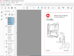
BT FORKLIFT REFLEX RR B,E RR B,E CC Service Manual 218920-040 – PDF DOWNLOAD
$29.95
BT FORKLIFT REFLEX RR B,E RR B,E CC Service Manual 218920-040 – PDF DOWNLOAD
Description
BT FORKLIFT REFLEX RR B,E RR B,E CC Service Manual 218920-040 – PDF DOWNLOAD
FILE DETAILS:
BT FORKLIFT REFLEX RR B,E RR B,E CC Service Manual 218920-040 – PDF DOWNLOAD
Language : English
Pages : 486
Downloadable : Yes
File Type : PDF
IMAGES PREVIEW OF THE MANUAL:
TABLE OF CONTENTS:
BT FORKLIFT REFLEX RR B,E RR B,E CC Service Manual 218920-040 – PDF DOWNLOAD
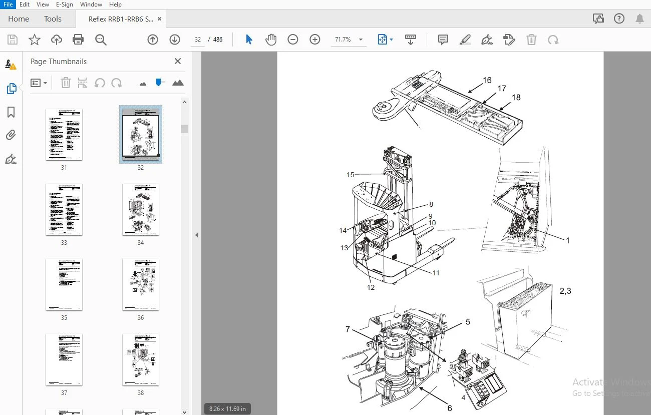
1- Table of contents........................................................................................  3
2- General product information - M2......................................................................... 25
	2.1 Presentation of the reach trucks.................................................................... 25
		2.1.1 Application areas for the reach trucks........................................................ 25
		2.1.2 Prohibited applications for the reach trucks.................................................. 25
	2.2 Truck data.......................................................................................... 26
	2.3 Truck dimensions.................................................................................... 27
	2.4 Identification plate, truck......................................................................... 29
		2.4.1 Capacity plate................................................................................ 29
		2.4.2 Modification plate............................................................................ 30
		2.4.3 Identification plate, mast.................................................................... 30
	2.5 Main components RR B/E 1-8.......................................................................... 31
	2.6 Main components RR B/E 2-8 CC....................................................................... 33
	2.7 Warning and information plates and symbols RR B/E 1-8............................................... 35
	2.8 Warning and information plates and symbols RR B/E 2-8 CC............................................ 37
3- Technical data - M4...................................................................................... 39
	3.1 General tightening torques.......................................................................... 43
		3.1.1 Galvanised, non-oiled bolts................................................................... 43
		3.1.2 Untreated, oiled bolts........................................................................ 43
4- Instructions for destruction - M6........................................................................ 45
	4.1 General............................................................................................. 45
	4.2 Procedure........................................................................................... 45
	4.3 Abbreviations....................................................................................... 46
	4.4 Sorting............................................................................................. 46
	4.5 Frame/chassis (0300)................................................................................ 47
		4.5.1 Dismantling................................................................................... 47
			Material handling............................................................................... 47
	4.6 Operator's seat, cushion (0620)..................................................................... 48
		4.6.1 Dismantling................................................................................... 48
			Material handling............................................................................... 48
	4.7 Cab heating/ventilation (0630)...................................................................... 49
		4.7.1 Dismantling................................................................................... 49
			Material handling............................................................................... 49
	4.8 Driver controls (0640).............................................................................. 50
		4.8.1 Dismantling................................................................................... 50
			Material handling............................................................................... 50
	4.9 Interior fittings RR-B (0680)....................................................................... 51
		4.9.1 Dismantling................................................................................... 51
			Material handling............................................................................... 52
	4.10 Interior fittings RR-E (0680)...................................................................... 53
		4.10.1 Dismantling.................................................................................. 53
			Material handling............................................................................... 54
	4.11 Interior fittings RR-B-CC (0680)................................................................... 55
		4.11.1 Dismantling.................................................................................. 55
			Material handling............................................................................... 56
	4.12 Interior fittings RR-E-CC (0680)................................................................... 57
		4.12.1 Dismantling.................................................................................. 57
			Material handling............................................................................... 58
	4.13 Rollover guard/head guard (0810)................................................................... 59
		4.13.1 Dismantling.................................................................................. 59
			Material handling............................................................................... 59
	4.14 Finger protectors (0820)........................................................................... 59
		4.14.1 Dismantling.................................................................................. 59
			Material handling............................................................................... 59
	4.15 Finger/foot protectors (0820)...................................................................... 60
		4.15.1 Dismantling.................................................................................. 60
			Material handling............................................................................... 60
	4.16 Finger/foot protectors (0820)...................................................................... 61
		4.16.1 Dismantling.................................................................................. 61
			Material handling............................................................................... 61
	4.17 Electric motors (1700)............................................................................. 62
		4.17.1 Dismantling.................................................................................. 62
			Material handling............................................................................... 62
	4.18 Electric fan motor (1740).......................................................................... 63
		4.18.1 Dismantling.................................................................................. 63
			Material handling............................................................................... 63
	4.19 Drive unit, final gear (2500)...................................................................... 64
		4.19.1 Dismantling.................................................................................. 64
			Material handling............................................................................... 64
	4.20 Wheels (3500)...................................................................................... 65
		4.20.1 Dismantling.................................................................................. 65
			Material handling............................................................................... 65
	4.21 Electric steering system (4300).................................................................... 66
		4.21.1 Dismantling.................................................................................. 67
			Material handling............................................................................... 67
	4.22 General electric equipment (5100).................................................................. 68
		4.22.1 Dismantling.................................................................................. 68
			Material handling............................................................................... 68
	4.23 Manöversystem, körfunktion (5300).................................................................. 69
		4.23.1 Dismantling.................................................................................. 69
			Material handling............................................................................... 69
	4.24 Power system, drive function (5400)................................................................ 70
		4.24.1 Dismantling.................................................................................. 70
			Material handling............................................................................... 70
	4.25 Control system, operation function (5500).......................................................... 71
		4.25.1 Dismantling.................................................................................. 71
			Material handling............................................................................... 71
	4.26 Steering/protective electronics (5700)............................................................. 72
		4.26.1 Dismantling.................................................................................. 72
			Material handling............................................................................... 72
	4.27 Hydraulic unit (6100).............................................................................. 73
		4.27.1 Dismantling.................................................................................. 74
			Material handling............................................................................... 74
	4.28 Hydraulic system, fitted on the chassis (6200)..................................................... 75
		4.28.1 Dismantling.................................................................................. 76
			Material handling............................................................................... 76
	4.29 Hydraulic system, fitted on the mast (6300)........................................................ 77
		4.29.1 Dismantling.................................................................................. 77
			Material handling............................................................................... 77
	4.30 Hydraulcylindrar (6600)............................................................................ 78
		4.30.1 Dismantling.................................................................................. 79
			Material handling............................................................................... 79
	4.31 Main mast (7100)................................................................................... 80
		4.31.1 Dismantling.................................................................................. 80
			Material handling............................................................................... 80
	4.32 Lift fork (7410)................................................................................... 81
		4.32.1 Dismantling.................................................................................. 81
			Material handling............................................................................... 81
	4.33 Optional electric equipment (9300)................................................................. 81
		4.33.1 Dismantling.................................................................................. 81
			Material handling............................................................................... 81
	4.34 Radio/CD player (9330)............................................................................. 82
		4.34.1 Dismantling.................................................................................. 82
			Material handling............................................................................... 82
	4.35 Extra work light (9360)............................................................................ 83
		4.35.1 Dismantling.................................................................................. 83
			Material handling............................................................................... 83
	4.36 Optional electric equipment (9400)................................................................. 84
		4.36.1 Dismantling.................................................................................. 84
			Material handling............................................................................... 84
	4.37 Optional electric equipment (9400)................................................................. 85
		4.37.1 Dismantling.................................................................................. 85
			Material handling............................................................................... 85
5- Introduction, maintenance - P1........................................................................... 87
	5.1 Safety regulations with maintenance work............................................................ 87
	5.2 Cleaning and washing................................................................................ 89
		5.2.1 External cleaning............................................................................. 89
		5.2.2 Cleaning the motor compartment................................................................ 89
		5.2.3 Electrical components......................................................................... 89
	5.3 Safe lifting........................................................................................ 90
	5.4 Opening of motor compartment........................................................................ 90
		5.4.1 RR B 1-8...................................................................................... 90
	5.5 Tilting the cab..................................................................................... 91
		5.5.1 RR E 1-8...................................................................................... 91
		5.5.2 RR E 2-8 CC................................................................................... 92
6- Preventive Maintenance - P2.............................................................................. 95
	6.1 Maintenance schedule................................................................................ 95
		6.1.1 RR B/E 1-8.................................................................................... 95
		6.1.2 RR B/E 2-8 CC.................................................................................105
7- Oil and grease specification - P3........................................................................115
8- Tools - P4...............................................................................................117
	8.1 Super Seal contact..................................................................................117
		8.1.1 AMP connector.................................................................................118
		8.1.2 Diverse tools.................................................................................119
9- Cab heating/ventilation - 0630...........................................................................125
	9.1 General.............................................................................................125
	9.2 Air conditioning unit...............................................................................125
		9.2.1 Ventilation...................................................................................125
		9.2.2 Main heater...................................................................................125
		9.2.3 Auxiliary heater..............................................................................125
		9.2.4 Temperature...................................................................................125
		9.2.5 Air direction.................................................................................126
		9.2.6 Fuses.........................................................................................126
		9.2.7 Air filter....................................................................................126
		9.2.8 Emergency exit (12)...........................................................................127
		9.2.9 Lighting......................................................................................127
10- Driver Protection - 0840................................................................................129
	10.1 General............................................................................................129
	10.2 Tilt stops.........................................................................................130
		10.1.1 Removing the tilt stops......................................................................131
11- Electric pump motor -1710...............................................................................133
	11.1 General............................................................................................133
	11.2 Dismantling the pump motor.........................................................................133
	11.3 Dismantling and assembling the pump motor..........................................................134
		11.3.1 Dismantling..................................................................................134
		11.3.2 Assembling...................................................................................134
	11.4 Bearing replacement................................................................................135
		11.4.1 Dismantling..................................................................................135
		11.4.2 Assembling...................................................................................136
	11.5 Installation instructions for external temperature sensor..........................................137
12- Electric steering motor - 1730..........................................................................141
	12.1 General............................................................................................141
	12.2 Replacing the steering motor.......................................................................141
		12.2.1 Dismantling..................................................................................141
		12.2.2 Assembling...................................................................................141
	12.3 Dismantling and assembling the carbon brushes......................................................142
13- Electric drive motor - 1760.............................................................................143
	13.1 General............................................................................................143
	13.2 Dismantling the drive motor........................................................................143
	13.3 Dismantling and assembling the drive motor.........................................................144
		13.3.1 Dismantling the drive motor..................................................................144
			Removing the gear wheel.........................................................................144
			Removing the brakes.............................................................................144
		13.3.2 Assembling the drive motor...................................................................145
		13.3.3 Assembling the brakes........................................................................145
			Assembling the gear wheel.......................................................................145
	13.4 Bearing replacement................................................................................146
		13.4.1 Dismantling..................................................................................146
		13.4.2 N-side.......................................................................................146
			D-side..........................................................................................146
		13.4.3 Assembling...................................................................................147
			N-side..........................................................................................147
			D-side..........................................................................................147
	13.5 Installation instructions for external temperature sensor..........................................148
14- Mechanical drive gear unit - 2550.......................................................................151
	14.1 General............................................................................................151
	14.2 Components/data for the drive assembly/transmission................................................151
		14.2.1 Component placement..........................................................................152
		14.2.2 Technical data...............................................................................154
		14.2.3 Dismantling the transmission.................................................................154
	14.3 Replacing the drive motor/drive transmission.......................................................155
		14.3.1 Dismantling the drive motor..................................................................155
		14.3.2 Dismantling the gear wheel...................................................................155
		14.3.3 Dismantling the drive transmission...........................................................156
		14.3.4 Assembling the transmission..................................................................156
		14.3.5 Installing the drive motor...................................................................157
		14.3.6 Assembling the gear wheel....................................................................157
	14.4 Checking/replacing the oil.........................................................................158
		14.4.1 Checking/refilling the oil...................................................................158
		14.4.2 Changing the Oil.............................................................................158
	14.5 Repairs............................................................................................159
		14.5.1 Replacing the drive shaft sealing ring.......................................................159
			Dismantling.....................................................................................159
			Assembling......................................................................................160
		14.5.2 Leakage from the upper cover.................................................................161
		14.5.3 Leakage from the lower cover.................................................................161
		14.5.4 Replacing wheel bolts........................................................................162
15- Travel brake system - 3100.1............................................................................163
	Without support arm brakes..............................................................................163
	15.1 General............................................................................................163
	15.2 Operating description..............................................................................163
		15.2.1 Releasing the accelerator....................................................................164
		15.2.2 Travel direction selector....................................................................164
		15.2.3 Pressing down the brake pedal................................................................165
		15.2.4 Parking brake................................................................................166
		15.2.5 Emergency brake..............................................................................166
	15.3 Electromechanical disc brake, drive motor..........................................................167
		15.3.1 Assembling...................................................................................167
		15.3.2 Dismantling..................................................................................168
		15.3.3 Inspection...................................................................................168
		15.3.4 Assembling...................................................................................168
	15.4 Maintenance........................................................................................169
		15.4.1 Adjusting the play...........................................................................169
		15.4.2 Wear.........................................................................................169
		15.4.3 Check the braking force......................................................................170
16- Travel brake system - 3100.2............................................................................171
	With support arm brake..................................................................................171
	16.1 General............................................................................................171
	16.2 Operating description..............................................................................171
		16.2.1 Releasing the accelerator....................................................................172
		16.2.2 Travel direction selector....................................................................172
		16.2.3 Pressing down the brake pedal................................................................173
		16.2.4 Parking brake................................................................................174
		16.2.5 Emergency braking............................................................................174
	16.3 Electromechanical disc brake, drive motor..........................................................175
		16.3.1 Assembling...................................................................................175
		16.3.2 Dismantling..................................................................................176
		16.3.3 Inspection...................................................................................176
		16.3.4 Assembling...................................................................................176
	16.4 Maintenance........................................................................................177
		16.4.1 Adjusting the play...........................................................................177
		16.4.2 Wear.........................................................................................177
		16.4.3 Check the braking force......................................................................178
	16.5 Multiple disc brake, support arm...................................................................179
		16.5.1 Assembling...................................................................................179
		16.5.2 Dismantling..................................................................................180
		16.5.3 Inspection...................................................................................181
		16.5.4 Assembling...................................................................................181
	16.6 Maintenance........................................................................................181
		16.6.1 Adjusting the play...........................................................................182
17- Drive wheel - 3530......................................................................................183
	17.1 General............................................................................................183
	17.2 Dismantling the drive wheel........................................................................183
	17.3 Assembling the drive wheel.........................................................................183
18- Fork/support arm wheel - 3550...........................................................................185
	18.1 General............................................................................................185
	18.2 Dismantling the wheel..............................................................................186
	18.3 Assembling the wheel...............................................................................187
	18.4 Dismantling/assembling the wheel bearings..........................................................189
		18.4.1 265 mm wheel and 300 mm wheels without brakes................................................189
			Dismantling the bearing.........................................................................189
			Assembling the bearing..........................................................................189
		18.4.2 300 mm wheel with brake and 350 mm wheel.....................................................190
			Dismantling the bearing.........................................................................190
			Assembling the bearing..........................................................................190
19- Mechanical steering system - 4100.......................................................................191
	19.1 General............................................................................................191
	19.2 Replacing the steering generator...................................................................191
		19.2.1 Dismantling..................................................................................191
		19.2.2 Assembling...................................................................................191
20- Steering angle sensor - 4350............................................................................193
	20.1 General............................................................................................193
	20.2 Procedure..........................................................................................193
		20.1.1 Adjustment of the steering angle sensor......................................................194
21- Electrical system - 5000................................................................................195
	21.1 General............................................................................................195
		21.1.1 Electrical panel.............................................................................195
	21.2 Symbols and electrical diagrams....................................................................196
		21.2.1 List of symbols..............................................................................196
		21.2.2 Electrical diagram (1/16)....................................................................199
		21.2.3 Electrical diagram (2/16)....................................................................200
		21.2.4 Electrical diagram (3/16)....................................................................201
		21.2.5 Electrical diagram (4/16)....................................................................202
		21.2.6 Electrical diagram (5/16)....................................................................203
		21.2.7 Electrical diagram (6/16)....................................................................204
		21.2.8 Electrical diagram (7/16)....................................................................205
		21.2.9 Electrical diagram (8/16)....................................................................206
		21.2.10 Electrical diagram (9/16)...................................................................207
		21.2.11 Electrical diagram (10/16)..................................................................208
		21.2.12 Electrical diagram (11/16)..................................................................209
		21.2.13 Electrical diagram (12/16)..................................................................210
		21.2.14 Electrical diagram (13/16)..................................................................211
		21.2.15 Electrical diagram (14/16)..................................................................212
		21.2.16 Electrical diagram (15/16)..................................................................213
		21.2.17 Electrical diagram (16/16)..................................................................214
	21.3 List of components.................................................................................215
		21.3.1 Picture 1....................................................................................221
		21.3.2 Picture 2....................................................................................221
		21.3.3 Picture 3....................................................................................222
		21.3.4 Picture 4....................................................................................222
		21.3.5 Picture 5....................................................................................223
		21.3.6 Picture 6....................................................................................224
		21.3.7 Picture 7....................................................................................224
		21.3.8 Picture 8....................................................................................225
		21.3.9 Picture 9....................................................................................226
		21.3.10 Picture 10..................................................................................227
		21.3.11 Picture 11..................................................................................228
		21.3.12 Picture 12..................................................................................228
	21.4 Description of function............................................................................229
		21.4.1 Truck not switched on........................................................................229
		21.4.2 Truck switched on............................................................................230
		21.4.3 Selection of travel direction................................................................231
			With the steering console.......................................................................231
			With the left-hand handle.......................................................................231
			With the speed control..........................................................................231
		21.4.4 Driving......................................................................................232
		21.4.5 Steering.....................................................................................233
		21.4.6 Steering wheel indicator.....................................................................233
		21.4.7 Braking......................................................................................234
			Auto plug braking...............................................................................234
			Motor brake (electric)..........................................................................234
			Foot brake......................................................................................234
			Parking brake...................................................................................234
		21.4.8 Fork lift....................................................................................235
		21.4.9 Maximum height...............................................................................235
		21.4.10 Maximum height..............................................................................235
		21.4.11 Fork lowering...............................................................................236
		21.4.12 Mast out/in.................................................................................236
		21.4.13 Fork tilt up/down...........................................................................236
		21.4.14 Hydraulic function 4........................................................................237
		21.4.15 Hydraulic function 5........................................................................237
		21.4.16 Cabin tilt..................................................................................238
		21.4.17 Height indication...........................................................................239
		21.4.18 Height selection............................................................................239
		21.4.19 Weight measurement..........................................................................239
		21.4.20 Driver identification.......................................................................240
			Without pin code................................................................................240
			With pin code...................................................................................240
22- Battery - 5110..........................................................................................241
	22.1 Battery dimensions.................................................................................241
23- Transistor panel - 5460.................................................................................243
	23.1 Frequency converter................................................................................243
		23.1.1 Terminal connections and pole bolts..........................................................244
		23.1.2 Technical Data...............................................................................245
		23.1.3 Installation of new frequency converter on truck.............................................245
		23.1.4 Programming..................................................................................245
24- Electronic card - 5710..................................................................................247
	24.1 General description................................................................................247
	24.2 Terminal connections and voltages on A5............................................................248
		24.2.1 10X..........................................................................................248
		24.2.2 20X..........................................................................................249
		24.2.3 30X..........................................................................................249
		24.2.4 40X..........................................................................................250
		24.2.5 50X..........................................................................................250
		24.2.6 60X..........................................................................................251
		24.2.7 70X..........................................................................................251
		24.2.8 80X..........................................................................................252
		24.2.9 90X..........................................................................................252
	24.3 Adjusting the lowering speed.......................................................................253
	24.4 Displaying and programming.........................................................................254
		24.4.1 Keypad.......................................................................................254
			Clock...........................................................................................255
			Driver parameters 1-7...........................................................................255
	24.5 Parameter setting of all parameters................................................................256
		Clock...............................................................................................256
		Parameters..........................................................................................257
		24.5.1 Parameter 1..................................................................................261
		24.5.2 Parameter 2..................................................................................261
		24.5.3 Parameter 3..................................................................................261
		24.5.4 Parameter 4..................................................................................261
		24.5.5 Parameter 5..................................................................................261
		24.5.6 Parameters 6 and 7...........................................................................261
		24.5.7 Parameter 11.................................................................................261
		24.5.8 Parameter 12.................................................................................261
		24.5.9 Parameters 13 and 14.........................................................................261
		24.5.10 Parameters 15 and 16........................................................................262
		24.5.11 Parameters 17 and 18........................................................................262
		24.5.12 Parameter 19................................................................................263
		24.5.13 Parameter 20................................................................................263
		24.5.14 Parameter 21................................................................................263
		24.5.15 Parameter 22................................................................................265
		24.5.16 Parameter 23................................................................................265
		24.5.17 Parameter 24................................................................................265
		24.5.18 Parameter 25................................................................................265
		24.5.19 Parameter 26................................................................................265
		24.5.20 Parameter 27................................................................................265
		24.5.21 Parameter 28................................................................................266
		24.5.22 Parameter 29................................................................................266
		24.5.23 Parameter 30................................................................................266
		24.5.24 Parameter 37................................................................................266
		24.5.25 Parameter 38................................................................................267
		24.5.26 Parameter 39................................................................................268
		24.5.27 Parameters 40 to 42.........................................................................268
		24.5.28 Miscellaneous parameters....................................................................268
	24.6 Operating hours....................................................................................269
		24.6.1 Installing a new electronic card in the truck................................................269
	24.7 Warning codes......................................................................................270
	24.8 Error Codes........................................................................................271
		24.8.1 Error mode...................................................................................271
		24.8.2 Safety logic.................................................................................272
		24.8.3 Warning Codes without registration...........................................................272
	24.9 Warning codes with registration....................................................................293
	24.10 Error Codes.......................................................................................312
		24.10.1 Error codes with registration...............................................................313
25- Keypad..................................................................................................345
	25.1 General............................................................................................345
	25.2 Display............................................................................................345
		25.2.1 Description of the keypad symboles...........................................................346
	25.3 Function...........................................................................................347
		25.3.1 Function 0...................................................................................347
		25.3.2 Function 1...................................................................................347
		25.3.3 Function 2...................................................................................347
		25.3.4 Function 3...................................................................................348
	25.4 Programming........................................................................................348
		25.4.1 LED status...................................................................................348
		25.4.2 Driver PIN-codes.............................................................................349
26- Hydraulic system - 6000.................................................................................351
	26.1 General............................................................................................351
	26.2 Symbols............................................................................................351
		26.2.1 Hydraulic diagram 1(4).......................................................................353
		26.2.2 Hydraulic diagram 2(4).......................................................................354
		26.2.3 Hydraulic diagram 3(4).......................................................................355
		26.2.4 Hydraulic diagram 4(4).......................................................................356
	26.3 List of symbols....................................................................................357
		26.3.1 Component placement 1 (3)....................................................................359
		26.3.2 Component placement 2 (3)....................................................................360
		26.3.3 Component placement 3(3).....................................................................361
	26.4 Adjusting fork lowering............................................................................362
	26.5 Setting the maximum lifting capacity...............................................................363
27- Hydraulic pump - 6140...................................................................................365
	27.1 General............................................................................................365
	27.2 Replacing the hydraulic pump.......................................................................365
		27.2.1 Dismantling..................................................................................365
		27.2.2 Assembling...................................................................................366
28- Hydraulic connections - 6230............................................................................367
	28.1 General............................................................................................367
	28.2 Tightening torque for hydraulic connections........................................................367
		28.2.1 Conical connection with O-ring...............................................................367
		28.2.2 Tredo seal...................................................................................368
		28.2.3 Pipe coupling................................................................................368
		28.2.4 Connection screwed into aluminium............................................................368
		28.2.5 Connection screwed into steel................................................................369
			Pressure class L................................................................................369
29- Mast mounted hose reel - 6370...........................................................................371
	29.1 General............................................................................................371
	29.2 Assembling.........................................................................................371
	29.3 Check after assembly...............................................................................372
30- Main lift cylinder - 6610...............................................................................373
	30.1 General............................................................................................373
	30.2 Tools..............................................................................................373
	30.3 Dismantling the lift cylinders from the mast.......................................................374
	30.4 Dismantling the cylinder...........................................................................374
		30.4.1 Dismantling the rod seal, guide ring, guide ring holder and locking ring in lift cylinder....375
		30.4.2 Fit the locking ring, rod seal, guide ring and guide ring holder in the lift cylinder........375
		30.4.3 Dismantling and assembling the hose rupture valve............................................376
	30.5 Assembling the cylinder............................................................................376
		30.5.1 Assembling the cylinder in the mast..........................................................376
31- Free lift cylinder - 6620...............................................................................377
	31.1 General............................................................................................377
	31.2 Tools..............................................................................................377
	31.3 Dismantling........................................................................................378
		31.3.1 Dismantling the cylinder.....................................................................379
	31.4 Dismantle the rod seal and the support rin.........................................................379
		31.4.1 Assembling the rod seal and the support ring.................................................379
	31.5 Dismantling the ram................................................................................380
		31.5.1 Assembling the ram in the free lift cylinder.................................................380
	31.6 Dismantling and assembling the hose rupture valve..................................................380
	31.7 Assembling the cylinder............................................................................381
	31.8 Assembling.........................................................................................381
32- Reach cylinder - 6650...................................................................................383
	32.1 General............................................................................................383
	32.2 Assembling and dismantling the reach cylinder......................................................383
	32.3 Dismantling........................................................................................383
		32.3.1 Dismantling the cylinder.....................................................................384
		32.3.2 Dismantle the rod seal and the support ring..................................................384
		32.3.3 Assembling the rod seal and the support ring.................................................384
		32.3.4 Dismantling the ram..........................................................................385
		32.3.5 Assembling the ram...........................................................................385
		32.3.6 Assembling the cylinder......................................................................385
	32.4 Assembling.........................................................................................385
33- Tilt cylinder - 6660.1..................................................................................387
	33.1 General............................................................................................387
	33.2 Mast with valve on the fork carriage...............................................................388
		33.2.1 Dismantling the fork carriage................................................................388
		33.2.2 Dismantling the cylinder.....................................................................389
		33.2.3 Dismantling the rod seal.....................................................................389
		33.2.4 Dismantling the ram..........................................................................389
		33.2.5 Assembling the ram...........................................................................389
		33.2.6 Assembling the rod seal......................................................................390
		33.2.7 Assembling the cylinder......................................................................390
		33.2.8 Assembling the fork carriage.................................................................390
	33.3 Mast without valve on the fork carriage............................................................391
		33.3.1 Dismantling the fork carriage................................................................391
		33.3.2 Dismantling the cylinder.....................................................................392
		33.3.3 Dismantling the rod seal.....................................................................392
		33.3.4 Dismantling the ram..........................................................................392
		33.3.5 Assembling the ram...........................................................................392
		33.3.6 Assembling the rod seal......................................................................393
		33.3.7 Assembling the cylinder......................................................................393
		33.3.8 Assembling the fork carriage.................................................................393
34- Tilt cylinder - 6660.2..................................................................................395
	34.1 General............................................................................................395
	34.2 Dismantling the cylinder from the truck............................................................395
	34.3 Dismantling and assembling the cylinder............................................................396
		34.3.1 Dismantling the cylinder.....................................................................396
		34.3.2 Dismantle the seals and the support ring.....................................................396
		34.3.3 Assembling the rod seal and the support ring.................................................397
		34.3.4 Dismantling the ram..........................................................................397
		34.3.5 Assembling the ram...........................................................................397
		34.3.6 Assembling the cylinder......................................................................397
	34.4 Refitting the cylinder in the truck................................................................398
35- Main mast - 7100........................................................................................399
	35.1 General............................................................................................399
	35.2 List of tools......................................................................................399
	35.3 Transporting the truck.............................................................................400
	35.4 Assembling the mast................................................................................401
	35.5 Dismantling the mast...............................................................................405
	35.6 Adjust the play....................................................................................407
		35.6.1 Adjusting the mast play......................................................................410
			Lateral play....................................................................................410
		35.6.2 Radial play..................................................................................411
	35.7 Assembly...........................................................................................411
36- Main lift chain system - 7120...........................................................................413
	36.1 General............................................................................................413
	36.2 Checking the chain setting.........................................................................413
	36.3 Chain inspection...................................................................................413
		36.3.1 Noise........................................................................................413
		36.3.2 Surface rust.................................................................................413
		36.3.3 Rusty links..................................................................................413
		36.3.4 Stiff links..................................................................................414
		36.3.5 Bolt rotation................................................................................414
		36.3.6 Loose bolts..................................................................................414
		36.3.7 Outline wear.................................................................................415
		36.3.8 Stretching...................................................................................415
		36.3.9 Damage.......................................................................................416
		36.3.10 Damaged discs...............................................................................416
		36.3.11 Damaged bolts...............................................................................417
		36.3.12 Dirty chain.................................................................................417
	36.4 Cleaning...........................................................................................417
	36.5 Lubrication........................................................................................417
37- Battery charger - 8340..................................................................................419
	37.1 General............................................................................................419
	37.2 Installation.......................................................................................420
	37.3 Functional description.............................................................................420
		37.3.1 Display functions............................................................................420
		37.3.2 Charging process.............................................................................420
		37.3.3 Shutdown conditions..........................................................................421
		37.3.4 Delayed power on and charging................................................................421
		37.3.5 Extra charging...............................................................................421
		37.3.6 Equalised charging...........................................................................422
		37.3.7 Current and voltage characteristics..........................................................422
		37.3.8 Safety shutdowns.............................................................................422
		37.3.9 Display and keyboard.........................................................................423
			Reading of analogue measurement values..........................................................423
			Error indication and error messages.............................................................424
			Reading statistics from the previous charge.....................................................425
			Reading of long term statistics.................................................................426
			Storing parameters..............................................................................426
			Reading parameters..............................................................................427
			Battery specific parameters.....................................................................427
			Charger specific parameters.....................................................................428
			Mains voltage codes.............................................................................428
			Other functions.................................................................................428
			Changing parameters.............................................................................429
		37.3.10 Acid circulation............................................................................429
			General.........................................................................................429
			BTM with acid circulation.......................................................................429
			Pump type APE, VPM..............................................................................430
			Pump type API...................................................................................430
	37.4 Service and maintenance............................................................................430
		37.4.1 Basic programming, code 30...................................................................430
		37.4.2 Resetting the statistics, code 31............................................................430
		37.4.3 Calibrating the measurement value............................................................431
			Calibrating the current’s zero value and temperatures, code 21..................................431
			Calibrating the battery voltage’s measurement value, code 20....................................431
			Calibrating the charging current, code 25.......................................................432
			Calibrating the mains voltage display, code 26..................................................432
		37.4.4 Calibrating and programming API..............................................................432
			Calibrating zero pressure.......................................................................432
			Calibrating the pressure........................................................................432
			Programming the alarm limits....................................................................432
			Programming the API function....................................................................433
		37.4.5 Adjusting the charging characteristics.......................................................433
		37.4.6 Trouble shooting.............................................................................434
			Error message, analysis and action..............................................................434
			Errors without indication.......................................................................435
		37.4.7 Trouble shooting acid circulation............................................................435
		37.4.8 Service measures.............................................................................435
			Switching to the timer charger..................................................................436
			Replacing the display card......................................................................436
			Replacing the computer board....................................................................437
			Replacing the mother board......................................................................437
			Replacing the diodes............................................................................437
		37.4.9 Preventive maintenance.......................................................................437
38- Control/computer equipment - 8700.......................................................................439
	38.1 General............................................................................................439
	38.2 Connection.........................................................................................439
	38.3 Layout.............................................................................................440
		38.3.1 Main window..................................................................................440
		38.3.2 Nodes........................................................................................440
		38.3.3 Icons........................................................................................441
		38.3.4 Tool buttons and menu list...................................................................442
		38.3.5 Information window...........................................................................442
		38.3.6 Status row...................................................................................442
	38.4 Function for connection............................................................................443
	38.5 Function for disconnecting.........................................................................443
	38.6 Function for program downloading...................................................................443
		38.6.1 Normal loading...............................................................................444
		38.6.2 Loading in old versions of the electronic card...............................................444
		38.6.3 Emergency loading............................................................................444
	38.7 Function for truck report..........................................................................445
	38.8 Function for parameters............................................................................446
	38.9 Function for diagnostics...........................................................................448
		38.9.1 Signal colours...............................................................................448
		38.9.2 Tab for “Analogue”...........................................................................449
		38.9.3 Tab for “Temperature”........................................................................450
		38.9.4 Tab for “Digital”............................................................................451
	38.10 Other menu functions..............................................................................452
		38.10.1 Save to file................................................................................452
		38.10.2 Loading from a file.........................................................................452
		38.10.3 Resetting the CAN adapter...................................................................452
		38.10.4 Deleting the fault code log.................................................................452
		38.10.5 Resetting the hour meter....................................................................452
		38.10.6 Reading the fault code log..................................................................452
		38.10.7 Adjusting the date/time.....................................................................452
		38.10.8 Adjusting the hour meter on older cards.....................................................453
		38.10.9 Help........................................................................................453
			About TruckCom..................................................................................453
		38.10.10 Conclude...................................................................................453
	38.11 Specifications....................................................................................453
	38.12 Installation......................................................................................454
		38.12.1 Installation on a PC with Windows XP/ 2000/NT...............................................454
		38.12.2 IInstallation on a PC with Windows 95/ 98...................................................454
		38.12.3 In the event of any problems with communication with CAN....................................455
		38.12.4 Uninstallation..............................................................................455
39- Extra warning lights/alarm - 9370.......................................................................457
	39.1 General............................................................................................457
40- Position sensors - 9390.................................................................................459
	40.1 General............................................................................................459
	40.2 Height indication..................................................................................460
	40.3 Operation..........................................................................................461
	40.4 Display............................................................................................462
	40.5 Preset height......................................................................................463
	40.6 Operation..........................................................................................464
	40.7 Display............................................................................................465
		40.7.1 Description of the display symbols...........................................................466
	40.8 Assembly of height preset..........................................................................467
	40.9 Programming........................................................................................467
		40.9.1 Programming a level..........................................................................467
			Collection level................................................................................467
			Leaving level...................................................................................467
		40.9.2 Erasing programmed levels....................................................................468
	40.10 Automatic operations..............................................................................468
		40.10.1 Collect load................................................................................468
		40.10.2 Leaving a load..............................................................................469
		40.10.3 Control.....................................................................................469
	40.11 Parameters........................................................................................470
		40.11.1 Parameter 1.................................................................................470
		40.11.2 Parameter 2.................................................................................470
		40.11.3 Parameter 3.................................................................................471
		40.11.4 Parameter 4.................................................................................471
		40.11.5 Parameter 5.................................................................................471
		40.11.6 Parameter 7.................................................................................472
		40.11.7 Parameter 8.................................................................................472
		40.11.8 Parameter 9.................................................................................472
	40.12 Programming parameters............................................................................473
	40.13 Error codes.......................................................................................475
41- TV Equipment - 9390.....................................................................................476
	41.1 General............................................................................................476
	41.2 Fork-mounted camera................................................................................476
		41.2.1 Colour camera A51............................................................................477
		41.2.2 Monitor A50..................................................................................477
		41.2.3 Voltage converter A10........................................................................479
42- Truck Logging System, code lock - 9420..................................................................481
	42.1 General............................................................................................481
	42.2 SD 16..............................................................................................481
		42.2.1 Logging in with a PIN code (5 digits)........................................................481
		42.2.2 Logout.......................................................................................481
	42.3 Components.........................................................................................482
		If the truck does not start:........................................................................483
		If the truck does not start or it is not possible to cut the power:.................................483
	42.4 I/O module.........................................................................................484
DESCRIPTION:
BT FORKLIFT REFLEX RR B,E RR B,E CC Service Manual 218920-040 – PDF DOWNLOAD
General product information
Presentation of the reach trucks
The reach truck program is intended for handling pallets indoors or alternatively other types of loads using other load carriers. The trucks are operated seated in a protected and ergonomic operator position. The reach trucks are available in different size classes and have as standard a lifting capacity of up to 2500 kg and a lifting height of up to 11,5 m.
The trucks are equipped with a 48 V electrical system. The travel and lifting speeds are transistor controlled to provide smooth operations. In addition, the travel function and the different hydraulic functions have additional controls which further enhance these features. Different speeds, steering and cab tilt (optional) can be set using parameters to give the best possible individual setting for the functions.
S.S 05/01/2025