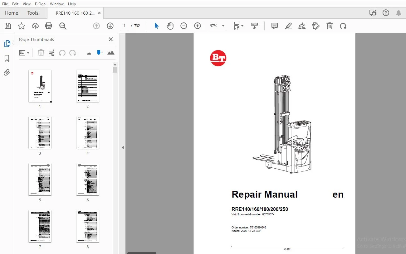
BT FORKLIFT RRE140/160/180/200/250 REPAIR MANUAL 6070557 – PDF DOWNLOAD
$32.95
BT FORKLIFT RRE140/160/180/200/250 REPAIR MANUAL 6070557 – PDF DOWNLOAD
Description
BT FORKLIFT RRE140/160/180/200/250 REPAIR MANUAL 6070557 – PDF DOWNLOAD
FILE DETAILS:
BT FORKLIFT RRE140/160/180/200/250 REPAIR MANUAL 6070557 – PDF DOWNLOAD
Language : English
Pages : 732
Downloadable : Yes
File Type : PDF
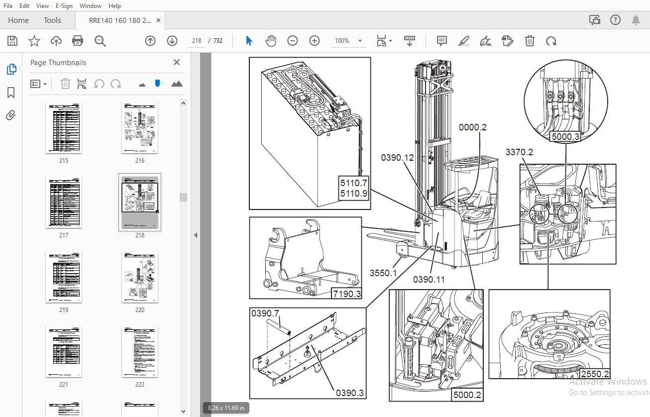
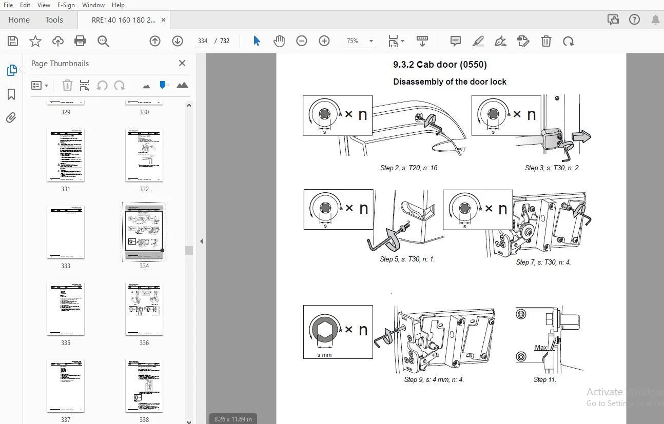
IMAGES PREVIEW OF THE MANUAL:
TABLE OF CONTENTS:
BT FORKLIFT RRE140/160/180/200/250 REPAIR MANUAL 6070557 – PDF DOWNLOAD
1 - Contents..................................................................................................................................................................  3
2 - General introduction...................................................................................................................................................... 19
	2.1 How to use the manual................................................................................................................................................. 19
	2.2 Warning symbols....................................................................................................................................................... 20
	2.3 Pictogram............................................................................................................................................................. 20
3 - General safety rules...................................................................................................................................................... 21
	3.1 Safety while working.................................................................................................................................................. 21
	3.2 Electrical system..................................................................................................................................................... 22
	3.3 Safe lifting.......................................................................................................................................................... 23
4 - Function descriptions..................................................................................................................................................... 25
	4.1 Chassis 0000.......................................................................................................................................................... 25
		4.1.1 Operator’s cabin (0500)......................................................................................................................................... 25
			Versions for cold-store cabs...................................................................................................................................... 25
			Emergency exit from the cab....................................................................................................................................... 26
		4.1.2 Cab windows (0530).............................................................................................................................................. 27
			Electrically heated windows....................................................................................................................................... 27
		4.1.3 Driver's seat (0620)............................................................................................................................................ 28
			Adjustment:....................................................................................................................................................... 28
			Button for seat heater............................................................................................................................................ 28
		4.1.4 Cab heating/ventilation (0630).................................................................................................................................. 29
			Climate control knobs............................................................................................................................................. 29
			Ventilation....................................................................................................................................................... 29
			Temperature....................................................................................................................................................... 29
		4.1.5 Driver protection (0840)........................................................................................................................................ 30
			Tilt stops........................................................................................................................................................ 30
			Overhead guard.................................................................................................................................................... 32
	4.2 Motors 1000........................................................................................................................................................... 33
		4.2.1 General......................................................................................................................................................... 33
		4.2.2 Electric pump motor (1710)...................................................................................................................................... 33
			General........................................................................................................................................................... 33
			Design............................................................................................................................................................ 33
		4.2.3 Electric steering motor (1730).................................................................................................................................. 34
			General........................................................................................................................................................... 34
			Design............................................................................................................................................................ 34
		4.2.4 Fan motor/fan (1740)............................................................................................................................................ 35
		4.2.5 Electric drive motor (1760)..................................................................................................................................... 36
			General........................................................................................................................................................... 36
			Design............................................................................................................................................................ 36
	4.3 Drive gear - 2000..................................................................................................................................................... 37
		4.3.1 General......................................................................................................................................................... 37
		4.3.2 Design.......................................................................................................................................................... 38
	4.4 Brake system 3100..................................................................................................................................................... 39
		4.4.1 General......................................................................................................................................................... 39
			Travel brake...................................................................................................................................................... 39
			Parking brake..................................................................................................................................................... 39
			Emergency brake................................................................................................................................................... 39
		4.4.2 Drive motor brake (travel brake)................................................................................................................................ 40
			Accelerator released.............................................................................................................................................. 40
			Changing the direction of travel.................................................................................................................................. 40
		4.4.3 Multiple disc brake, support arm (travel brake)................................................................................................................. 41
			General........................................................................................................................................................... 41
			Design............................................................................................................................................................ 41
		4.4.4 Disc brake on the drive motor (parking brake)................................................................................................................... 42
			General........................................................................................................................................................... 42
			Design............................................................................................................................................................ 42
	4.5 Steering system 4000.................................................................................................................................................. 43
		4.5.1 General......................................................................................................................................................... 43
		4.5.2 Design.......................................................................................................................................................... 43
		4.5.3 Sensors......................................................................................................................................................... 44
			Steering reference sensor......................................................................................................................................... 44
	4.6 Operator compartment.................................................................................................................................................. 45
		4.6.1 Truck control, overview......................................................................................................................................... 45
			Right-hand control panel, single control.......................................................................................................................... 45
			Right-hand control panel, multi-control........................................................................................................................... 45
			Emergency switch.................................................................................................................................................. 46
			Steering wheel module............................................................................................................................................. 47
			Pedals............................................................................................................................................................ 47
		4.6.2 Single control.................................................................................................................................................. 48
		4.6.3 Multi-control................................................................................................................................................... 49
		4.6.4 Central Information Display - CID............................................................................................................................... 50
			Navigation........................................................................................................................................................ 50
			LED symbols....................................................................................................................................................... 53
				a. Travel direction - left. Flashes when no travel direction is selected, comes on permanently when travel direction is the same as drive wheel direction..... 53
					b. Parking brake. Comes on when the parking brake is engaged.............................................................................................. 53
					c. Travel direction - right. Flashes when no travel direction is selected, comes on permanently when travel direction is the same as fork direction....... 53
					d. Stop. The truck has been stopped due to a critical fault............................................................................................... 53
					e. Cabin tilt. Cabin tilting is possible (RRE Ergo)....................................................................................................... 53
					f. Warning. Comes on when a warning is active............................................................................................................. 53
					g. Low battery. Battery capacity is low: flashing lamp when 10% remaining, comes on permanently at 0%..................................................... 53
					h. Extra. Comes on when an extra hydraulic function is selected........................................................................................... 53
			Information symbols............................................................................................................................................... 54
			Driver parameter symbols - Overview............................................................................................................................... 55
			Catch symbols - Overview.......................................................................................................................................... 56
			Service functions................................................................................................................................................. 58
			Calibration functions............................................................................................................................................. 60
			Configuration functions........................................................................................................................................... 62
			Other functions................................................................................................................................................... 65
		4.6.5 Load Information Display - LID (option)......................................................................................................................... 67
			LED symbols....................................................................................................................................................... 67
				a. Height preselector active (green).......................................................................................................................... 67
					b. Not used............................................................................................................................................... 67
					c. Sideshift in initial position (green).................................................................................................................. 67
					e. Aux (yellow)........................................................................................................................................... 67
					f. Not used............................................................................................................................................... 67
			Symbols in the display part....................................................................................................................................... 68
	4.7 Transducers and sensors (5800)........................................................................................................................................ 69
		4.7.1 Inductive sensors............................................................................................................................................... 69
		4.7.2 Position sensor................................................................................................................................................. 69
		4.7.3 Magnetic sensor................................................................................................................................................. 70
	4.8 Operation and connection sequences.................................................................................................................................... 71
	4.9 Functions.............................................................................................................................................................104
		4.9.1 General overview................................................................................................................................................104
			Key...............................................................................................................................................................104
			Components........................................................................................................................................................104
		4.9.2 MCU - main control unit.........................................................................................................................................105
			General...........................................................................................................................................................105
			Downloading software..............................................................................................................................................105
			System communication..............................................................................................................................................105
		4.9.3 ACT/ACH transistor regulators...................................................................................................................................106
			General...........................................................................................................................................................106
		4.9.4 Start-up........................................................................................................................................................106
		4.9.5 Shutdown........................................................................................................................................................107
		4.9.6 Driving.........................................................................................................................................................107
			Introduction......................................................................................................................................................107
			Acceleration and speed reduction..................................................................................................................................107
			Reversing.........................................................................................................................................................108
			Brake.............................................................................................................................................................108
			Travel speed......................................................................................................................................................109
		4.9.7 OTP.............................................................................................................................................................110
			Travel speed reduction - steering angle...........................................................................................................................110
			Travel speed reduction - extension of reach carriage..............................................................................................................110
			Travel speed reduction - mast splitting...........................................................................................................................110
			Prevention of lifting/lowering of the forks.......................................................................................................................110
			Reduced extension speed...........................................................................................................................................110
		4.9.8 Steering........................................................................................................................................................111
			Steering position check...........................................................................................................................................111
			Steering speed....................................................................................................................................................111
			Steering reference................................................................................................................................................112
			Travel speed limitation...........................................................................................................................................112
			Compass card......................................................................................................................................................112
		4.9.9 Hydraulic system................................................................................................................................................113
			Definitions.......................................................................................................................................................113
			Controls..........................................................................................................................................................113
			Lift..............................................................................................................................................................113
			Reach movement....................................................................................................................................................114
			Lift height limitation............................................................................................................................................114
			Maximum height limitation.........................................................................................................................................114
			Auxiliary/Extra functions (option)................................................................................................................................115
	4.10 Height preselector, description of function..........................................................................................................................116
		4.10.1 Using the height preselector...................................................................................................................................116
		4.10.2 Symbols........................................................................................................................................................116
		4.10.3 Buzzer.........................................................................................................................................................116
		4.10.4 Height preselector levels......................................................................................................................................117
		4.10.5 Level selection................................................................................................................................................117
		4.10.6 Height programming.............................................................................................................................................118
		4.10.7 Height preselector and TruckCom................................................................................................................................119
		4.10.8 Lift/lowering movement.........................................................................................................................................119
		4.10.9 Parameter settings, braking at height preselection.............................................................................................................120
	4.11 Hydraulic system 6000................................................................................................................................................121
		4.11.1 General........................................................................................................................................................121
		4.11.2 Tank...........................................................................................................................................................121
		4.11.3 Filter.........................................................................................................................................................121
			Return filter.....................................................................................................................................................121
			Dehumidification filter...........................................................................................................................................121
		4.11.4 Hydraulic pump.................................................................................................................................................122
		4.11.5 Valve block....................................................................................................................................................122
			Main valve block..................................................................................................................................................122
			Second valve block................................................................................................................................................123
		4.11.6 Cylinders......................................................................................................................................................124
			Main lift cylinders...............................................................................................................................................124
			Free lift cylinder................................................................................................................................................124
			Cylinders for the reach movement, cabin tilt, sideshift and fork tilt.............................................................................................124
		4.11.7 Lift and lowering function.....................................................................................................................................125
			Lifting and lowering of free lift.................................................................................................................................125
			Transition from free lift to main lift............................................................................................................................125
			Lifting and lowering of main lift.................................................................................................................................125
			Reach movement, in and out........................................................................................................................................125
			Simultaneous operation of mast lift and reach movement............................................................................................................126
		4.11.8 Extra functions................................................................................................................................................126
		4.11.9 Cabin tilt (RRE Ergo)..........................................................................................................................................126
			Hydraulic priority system.........................................................................................................................................126
			Cabin tilt (RRE Ergo) during servicing............................................................................................................................127
			Cabin tilt in the event of hydraulic or electrical power loss.....................................................................................................127
	4.12 Mast 7000............................................................................................................................................................128
		4.12.1 Mast and reach carriage........................................................................................................................................128
	4.13 Lifting devices......................................................................................................................................................129
		4.13.1 Fork extensions................................................................................................................................................129
		4.13.2 Telescopic forks...............................................................................................................................................129
	4.14 Accessories - 9000...................................................................................................................................................131
		4.14.1 Radio equipment................................................................................................................................................131
		4.14.2 Extra work lights..............................................................................................................................................131
		4.14.3 Extra warning light/alarm......................................................................................................................................132
		4.14.4 Direction indicators...........................................................................................................................................132
		4.14.5 Travel alarm...................................................................................................................................................133
		4.14.6 Positioning/TV equipment.......................................................................................................................................134
		4.14.7 Extra electrical equipment.....................................................................................................................................136
		4.14.8 Extra equipment, miscellaneous.................................................................................................................................137
			Fork spacers......................................................................................................................................................137
			Load support......................................................................................................................................................138
			E-bar.............................................................................................................................................................139
			Fire extinguisher.................................................................................................................................................140
5 - Parameters................................................................................................................................................................141
	5.1 General...............................................................................................................................................................141
	5.2 Displaying/changing parameters........................................................................................................................................141
	5.3 Operator parameters...................................................................................................................................................142
		5.3.1 Overview........................................................................................................................................................142
		5.3.2 Coupling to logged-in operator..................................................................................................................................143
		5.3.3 Description.....................................................................................................................................................144
			Parameter 1 (Steering)............................................................................................................................................144
			Parameter 2 and 3 - Maximum travel speed..........................................................................................................................146
			Parameters 4 and 5 - Acceleration/Retardation.....................................................................................................................146
			Parameter 6 - Cab tilt............................................................................................................................................146
	5.4 General service parameters............................................................................................................................................147
		5.4.1 Overview........................................................................................................................................................147
		5.4.2 Description.....................................................................................................................................................147
			Parameter 101/104 - Service/Log-out...............................................................................................................................147
			Parameter 105/106/114/115/117 (Travel alarms 1 and 2).............................................................................................................148
			Parameter 107/108 - Battery.......................................................................................................................................150
			Parameter 109/110/111/112 - Collision sensor......................................................................................................................153
			Parameter 113 (shunt value).......................................................................................................................................154
			Parameter 116 (Door for cold storage cab).........................................................................................................................155
		5.4.3 Service parameters, travel functions............................................................................................................................156
		5.4.4 Overview........................................................................................................................................................156
		5.4.5 Description.....................................................................................................................................................157
			Parameter 201 - Retardation when reversing........................................................................................................................157
			Parameter 202/203/204 - Adjusting erroneous, maximum travel speeds................................................................................................157
			Parameter 205/206/207 - Adjusting erroneous, maximum travel speeds................................................................................................158
			Parameter 208 - Creep speed in travel direction control...........................................................................................................159
			Parameter 209/210 - Reduced maximum travel speed above a certain lift height......................................................................................159
			Parameter 211/212 - Reduced maximum travel speed with a certain reach length......................................................................................160
			Parameter 213 - Permanently reduced maximum travel speed..........................................................................................................160
			Parameter 214 - Adjusting the maximum travel speed in main lift range.............................................................................................160
	5.5 Service parameters, hydraulics........................................................................................................................................161
		5.5.1 Overview........................................................................................................................................................161
		5.5.2 Description.....................................................................................................................................................164
			Parameter 301/302/303/304 - Extra valve function..................................................................................................................164
			Parameter 305/306/307/308 - Max. oil pressure through valve Q8....................................................................................................166
			Parameter 313/314/315/316 - Closing time..........................................................................................................................167
			Parameter 317/318/319/320 - Max. oil pressure through valve Q8....................................................................................................167
			Parameter 321/322/323/324 - Max. oil pressure through valve Q9....................................................................................................168
			Parameter 325/326/327/328 - Opening/closing time valve Q8.........................................................................................................168
			Parameter 329/330/331/332 - Opening/closing time valve Q9.........................................................................................................169
			Parameter 341/342 - Reducing the lifting/lowering speed...........................................................................................................169
			Parameter 343 - Reduction of reach speed..........................................................................................................................170
			Parameter 344 - Reduction of fork lowering speed before floor level...............................................................................................170
			Parameter 347/348 - Prevents the lifting/lowering of forks........................................................................................................171
			Parameter 349 - Fork weight.......................................................................................................................................171
			Parameter 350 - Multi-function....................................................................................................................................172
			Parameter 360 - Deactivation of hydraulic functions...............................................................................................................173
			Parameter 361/362/363/364/365 /366 - Function related, maximum lifting/lowering speeds............................................................................174
			Parameter 367/368 - Fork limit for deactivating the extension of the fork carriage and for sideshift..............................................................175
			Parameter 369 up to and including 379 - Height pre- selection.....................................................................................................176
			Parameter 380 up to and including 386 - Lift height limitations...................................................................................................178
			Parameters 387 up to and including 393 - Configuring the lift height limitations..................................................................................179
			Parameters 395, 396/397 Function-related, maximum lift heights....................................................................................................180
			Parameters 398/399 -Operator profile-dependent, maximum lift heights..............................................................................................181
	5.6 Service parameters, CID...............................................................................................................................................182
		5.6.1 Overview........................................................................................................................................................182
		5.6.2 Description.....................................................................................................................................................183
			Parameter 503 - Login method......................................................................................................................................183
			Parameter 504/505/506/507 - Smart Access..........................................................................................................................184
			Parameters 508/509/512/513/514 - CID configuration................................................................................................................188
			Parameter 510/511 - Height pre-selector...........................................................................................................................190
	5.7 General factory parameters............................................................................................................................................191
		5.7.1 Overview........................................................................................................................................................191
		5.7.2 Description.....................................................................................................................................................192
			Parameter 1001 (Truck type).......................................................................................................................................192
			Parameter 1002 - (Drive motor)....................................................................................................................................192
			Parameter 1003 - Pedal type.......................................................................................................................................192
			Parameter 1004 - Steering servo...................................................................................................................................193
			Parameter 1005 - Pump motor.......................................................................................................................................193
			Parameter 1006 - Hydraulic pump...................................................................................................................................193
			Parameter 1007 - Activation of hydraulic levers...................................................................................................................194
			Parameter 1008 - Mast type........................................................................................................................................194
			Parameter 1009 - Height indication................................................................................................................................195
			Parameter 1010 - Weight indicating................................................................................................................................195
	5.8 Factory parameters, activation of options.............................................................................................................................196
	5.9 Factory parameters, calibration.......................................................................................................................................198
6 - Installation..............................................................................................................................................................201
	6.1 Transporting the truck................................................................................................................................................201
		Method 1..............................................................................................................................................................201
		Method 2..............................................................................................................................................................201
	6.2 Initial operation.....................................................................................................................................................202
		6.2.1 Tool............................................................................................................................................................202
		6.2.2 Battery.........................................................................................................................................................202
			Placing the battery...............................................................................................................................................202
			Battery parameters................................................................................................................................................203
		6.2.3 Mast, fitting...................................................................................................................................................203
		6.2.4 Parameters on initial operation.................................................................................................................................203
			Load indicator....................................................................................................................................................203
			Ergo cabin........................................................................................................................................................204
			Cold store cabin..................................................................................................................................................204
		6.2.5 Parameters for optional equipment...............................................................................................................................205
			Height measurement (option).......................................................................................................................................205
			Travel speed limitation, height-dependent.........................................................................................................................205
			Travel speed limitation, reach movement dependent.................................................................................................................205
			Travel speed limitation, parameter-dependent......................................................................................................................206
			Collision sensor (BT).............................................................................................................................................206
		6.2.6 Test driving....................................................................................................................................................206
7 - Maintenance...............................................................................................................................................................209
	7.1 Introduction, maintenance.............................................................................................................................................209
	7.2 Safety regulations during maintenance work............................................................................................................................210
	7.3 Periodic maintenance..................................................................................................................................................212
		7.3.1 Every 500 B-hours/180 days......................................................................................................................................212
		7.3.2 Every 1,000 B-hours/360 days....................................................................................................................................214
		7.3.3 Every 2,000 B-hours/720 days....................................................................................................................................219
		7.3.4 Every 3,000 B-hours/1,080 days..................................................................................................................................219
		7.3.5 Every 5,000 B-hours/1,800 days..................................................................................................................................221
		7.3.6 Annual status inspection........................................................................................................................................221
	7.4 Maintenance instructions..............................................................................................................................................222
		7.4.1 Cleaning and washing............................................................................................................................................222
			High-pressure washers.............................................................................................................................................222
			Degreasing agents.................................................................................................................................................222
			Cleaning the exterior.............................................................................................................................................222
			Cleaning the chain................................................................................................................................................223
			Cleaning the motor compartment....................................................................................................................................223
			Electrical components.............................................................................................................................................223
8 - Troubleshooting...........................................................................................................................................................225
	8.1 Abbreviations used in this section....................................................................................................................................225
	8.2 Truck help functions..................................................................................................................................................225
		8.2.1 Error log menu..................................................................................................................................................225
			Description.......................................................................................................................................................225
			Driver............................................................................................................................................................225
		8.2.2 Error information menu..........................................................................................................................................226
			Description.......................................................................................................................................................226
			Driver............................................................................................................................................................226
		8.2.3 Diagnostic screens..............................................................................................................................................226
			Driver............................................................................................................................................................226
			State 1 - Voltage from the control console levers.................................................................................................................227
			State 2 - Digital signals from the truck control to CID...........................................................................................................228
			State 3 - Voltage from control/sensor to MCU......................................................................................................................229
			State 4 - Digital input signals to MCU............................................................................................................................232
			State 5 - Digital output signals from MCU.........................................................................................................................234
			State 6 - PWM output signals from MCU.............................................................................................................................235
			State 7 - FCU (not used)..........................................................................................................................................235
			State 8 - FCU (not used)..........................................................................................................................................235
			State 9 - GFU (not used)..........................................................................................................................................235
			State 10 - GFU (not used).........................................................................................................................................235
			State 11 - Temperature signals....................................................................................................................................236
			State 12 - Voltage levels.........................................................................................................................................236
			State 13 - Travel information.....................................................................................................................................237
			State 14 - Steering information...................................................................................................................................238
			State 15 - Lift/lowering information..............................................................................................................................239
			Stage 16 - Reach movement information.............................................................................................................................240
			Stage 17 - Hydraulic information..................................................................................................................................241
	8.3 Initial troubleshooting...............................................................................................................................................243
	8.4 Troubleshooting using catch symbol....................................................................................................................................244
	8.5 Troubleshooting using error code......................................................................................................................................251
		8.5.1 CID, warnings and errors........................................................................................................................................253
		8.5.2 MCU and other warnings and errors...............................................................................................................................257
		8.5.3 Drive system error..............................................................................................................................................267
		8.5.4 Hydraulic system error..........................................................................................................................................279
		8.5.5 Steering system, warnings and errors............................................................................................................................314
		8.5.6 GFU, warnings and errors........................................................................................................................................321
	8.6 Troubleshooting without indications...................................................................................................................................322
		8.6.1 Mechanical brake (3000).........................................................................................................................................322
		8.6.2 Steering (4000).................................................................................................................................................322
		8.6.3 Telescopic forks................................................................................................................................................323
		8.6.4 Log-in normal but one or more functions cannot be used..........................................................................................................324
9 - Frame/Chassis 0000........................................................................................................................................................327
	9.1 General...............................................................................................................................................................327
	9.2 Motor hood (0340).....................................................................................................................................................327
		9.2.1 Opening the motor compartment...................................................................................................................................327
			RRE 140-RRE 250...................................................................................................................................................327
			To open the motor compartment:....................................................................................................................................327
			To close the motor compartment:...................................................................................................................................327
			Replacing the motor hood..........................................................................................................................................328
			Adjustment of motor hood..........................................................................................................................................328
	9.3 Battery compartment components (0390).................................................................................................................................330
		9.3.1 Adjusting the battery bed.......................................................................................................................................330
	9.4 Operator's cab (0500).................................................................................................................................................331
		9.4.1 Cab tilting RRE 140 - 250 Ergo..................................................................................................................................331
		9.3.1 Cab windows (0530)..............................................................................................................................................332
			Fitting a window..................................................................................................................................................332
		9.3.2 Cab door (0550).................................................................................................................................................334
			Disassembly of the door lock......................................................................................................................................334
			Tools required....................................................................................................................................................335
			Method............................................................................................................................................................335
			Disassembly of the lock device....................................................................................................................................336
	9.4 Operator compartment (0600)...........................................................................................................................................338
		9.4.1 Operator's seat (0620)..........................................................................................................................................338
			Disassembling the entire seat.....................................................................................................................................338
			Replacing the seat switch.........................................................................................................................................339
			Replacing the back rest...........................................................................................................................................340
			Replacing the chair seat..........................................................................................................................................341
			Replacing the seat heater switch..................................................................................................................................341
		9.4.2 Cab heating/ventilation (0630)..................................................................................................................................342
			Replacing the air filter on the cold store cabin:.................................................................................................................342
			Removing the fan and heater.......................................................................................................................................343
			Replacing the potentiometers......................................................................................................................................347
		9.4.3 Internal fittings (0680)........................................................................................................................................349
		9.4.4 Disassembling/assembling the floor plate, B version 0680........................................................................................................350
	9.5 Safety equipment (0800)...............................................................................................................................................352
		9.5.1 Checking the overhead guard (0810)..............................................................................................................................352
		9.5.2 Adjusting the tilt stops (0840).................................................................................................................................353
10 - Motors 1000..............................................................................................................................................................355
	10.1 Motor sensors........................................................................................................................................................355
		10.1.1 Temperature sensor.............................................................................................................................................355
			Retrofitting an external temperature sensor.......................................................................................................................356
		10.1.2 Replacing the motor speed sensor...............................................................................................................................356
	10.2 Pump motor (1710)....................................................................................................................................................357
		10.2.1 General........................................................................................................................................................357
			The pump motor dismantled.........................................................................................................................................357
		10.2.2 Replacing the bearing on the pump motor........................................................................................................................358
			Dismantling the pump motor........................................................................................................................................358
			Reassembling the pump motor.......................................................................................................................................360
	10.3 Steering motor and steering unit (1730)..............................................................................................................................361
		10.3.1 General........................................................................................................................................................361
		10.3.2 Layout of the flange holes.....................................................................................................................................361
		10.3.3 Removing the steering motor from the truck.....................................................................................................................362
		10.3.4 Fitting the steering motor in the truck........................................................................................................................362
	10.4 Fan motor/fan (1740).................................................................................................................................................363
		10.4.1 General........................................................................................................................................................363
		10.4.2 Replacing the frequency converter cooling fan..................................................................................................................363
			Standard truck....................................................................................................................................................363
			Ergo truck........................................................................................................................................................363
		10.4.3 Replacing the motor compartment cooling fan....................................................................................................................365
	10.5 Drive motor (1760)...................................................................................................................................................366
		10.5.1 General........................................................................................................................................................366
			The drive motor dismantled........................................................................................................................................366
		10.5.2 Removing the drive motor from the truck........................................................................................................................367
		10.5.3 Dismantling the drive motor....................................................................................................................................369
		10.5.4 Cleaning.......................................................................................................................................................370
		10.5.5 Assembling the drive motor.....................................................................................................................................371
		10.5.6 Fitting the drive motor in the truck...........................................................................................................................373
11 - Drive gear 2000..........................................................................................................................................................375
	11.1 General..............................................................................................................................................................375
	11.2 Repairs/servicing....................................................................................................................................................375
	11.3 Actions..............................................................................................................................................................376
		11.3.1 Checking the oil level.........................................................................................................................................376
		11.3.2 Changing the oil...............................................................................................................................................376
		11.3.3 Leakage from the bottom cover..................................................................................................................................378
		11.3.4 Replacing the drive gear.......................................................................................................................................379
			Special tools.....................................................................................................................................................379
			Exposing the drive gear...........................................................................................................................................379
			Removing the drive motor from the truck...........................................................................................................................379
			Removing the steering motor from the truck........................................................................................................................379
			Removing the drive gear from the truck............................................................................................................................380
			Replacing the drive gear in the truck.............................................................................................................................382
			Fitting the steering motor in the truck...........................................................................................................................383
			Fitting the drive motor in the truck..............................................................................................................................383
			Completion work...................................................................................................................................................383
12 - Brake and wheel 3000.....................................................................................................................................................385
	12.1 Travel brake system (3100)...........................................................................................................................................385
		12.1.1 Removing the support arm's multiple disc brake.................................................................................................................385
		12.1.2 Dismantling the multiple disc brake............................................................................................................................385
			Inspection........................................................................................................................................................386
			Adjusting play....................................................................................................................................................386
			Assembling the multiple disc brake................................................................................................................................387
		12.1.3 Installing the multiple disc brake in the truck................................................................................................................387
		12.1.4 Checking the wheel brake's brake force.........................................................................................................................388
	12.2 Parking brake (3300).................................................................................................................................................389
		12.2.1 General........................................................................................................................................................389
			a. Fixing screws..................................................................................................................................................389
				b. Magnet housing.............................................................................................................................................389
				c. Pressure plate.............................................................................................................................................389
				d. Adjusting screws...........................................................................................................................................389
				e. Friction disc..............................................................................................................................................389
				f. Pressure plate (fixed).....................................................................................................................................389
				g. Locking screws.............................................................................................................................................389
				h. Hub........................................................................................................................................................389
		12.2.2 Emergency release of the parking brake.........................................................................................................................390
		12.2.3 Checking the brake force.......................................................................................................................................390
		12.2.4 Removing the parking brake from the truck......................................................................................................................391
			Dismantling and checking for wear.................................................................................................................................392
			Adjusting the air gap.............................................................................................................................................394
		12.2.5 Installing the parking brake in the truck......................................................................................................................396
	12.3 Drive wheel (3530)...................................................................................................................................................397
		12.3.1 General........................................................................................................................................................397
		12.3.2 Removing the drive wheel from the truck........................................................................................................................397
		12.3.3 Installing the drive wheel on the truck........................................................................................................................397
	12.4 Wheel bolt (3530)....................................................................................................................................................398
		General...............................................................................................................................................................398
		12.4.1 Replacing wheel bolts..........................................................................................................................................398
	12.5 Support arm wheel (3550).............................................................................................................................................399
		12.5.1 Removing the support arm wheel from the truck..................................................................................................................399
		12.5.2 Replacing a wheel bearing - braked wheel (A)...................................................................................................................400
		12.5.3 Replacing a wheel bearing - unbraked wheel (B).................................................................................................................401
		12.5.4 Fitting the support arm wheel to the truck.....................................................................................................................402
		12.5.5 Wheel wear and tear............................................................................................................................................403
13 - Steering system 4000.....................................................................................................................................................405
	13.1 Electric steering wheel (4310).......................................................................................................................................405
		13.1.1 General........................................................................................................................................................405
		13.1.2 Replacing the pulse transducer on the steering wheel module....................................................................................................405
		13.1.3 Removing the operating console from the truck..................................................................................................................406
		13.1.4 Replacing the wiring harness in the operating console..........................................................................................................407
		13.1.5 Fitting the operating console in the truck.....................................................................................................................409
	13.2 Steering reference sensor (4350).....................................................................................................................................410
		General...............................................................................................................................................................410
		13.2.1 Replacing the reference transducer [B17].......................................................................................................................410
	13.3 Steering bearings (4380).............................................................................................................................................411
		13.3.1 Removing a steering bearing from the drive gear................................................................................................................411
		13.3.2 Fitting a steering bearing on the drive gear...................................................................................................................411
14 - Electrical system 5000...................................................................................................................................................413
	14.1 Battery (5110).......................................................................................................................................................413
		14.1.1 Battery recommendation.........................................................................................................................................413
			Exide gel batteries (Sonnenschein, for example)...................................................................................................................413
			Hawker Evolution gel batteries....................................................................................................................................413
		14.1.2 Battery installation...........................................................................................................................................414
			Replacement/installation of battery...............................................................................................................................414
			Procedure without battery changing table..........................................................................................................................415
			Procedure with battery changing table.............................................................................................................................415
	14.2 LID (5200)...........................................................................................................................................................416
		14.2.1 Replacement of LID.............................................................................................................................................416
		14.2.2 Replacement of LID cold store cab..............................................................................................................................417
	14.3 Replacing pedals.....................................................................................................................................................418
		14.3.1 Replacing/repairing safety pedal...............................................................................................................................419
	14.4 Control console (5510)...............................................................................................................................................420
		14.4.1 General........................................................................................................................................................420
		14.4.2 Replacement/installation of a control..........................................................................................................................420
		14.4.3 Replacing the multi-function control...........................................................................................................................421
			Replacing the multi-function control's buttons....................................................................................................................421
		14.4.4 Remove the control console from the truck......................................................................................................................422
		14.4.5 Replacing the access card's circuit board......................................................................................................................423
		14.4.6 Dismantling the control console................................................................................................................................424
			Installing an extra push button...................................................................................................................................426
			Replacing the travel direction selector with signal button........................................................................................................426
			Replacing the display.............................................................................................................................................427
		14.4.7 Assembling the control console.................................................................................................................................427
		14.4.8 Placing the control console in the truck.......................................................................................................................428
	14.5 Magnetic sensor (5850)...............................................................................................................................................430
		General...............................................................................................................................................................430
		14.5.1 Replacing the magnetic sensor [B47]............................................................................................................................430
		14.5.2 Reference magnet...............................................................................................................................................431
	14.6 Parameter settings...................................................................................................................................................432
		14.6.1 Configuration menu.............................................................................................................................................432
			Calendar/hour counter menu........................................................................................................................................432
			Parameter menu (PAR)..............................................................................................................................................432
			Setting driver parameters.........................................................................................................................................433
	14.7 PIN menu.............................................................................................................................................................434
		14.7.1 Menu for activating a PIN block................................................................................................................................435
		14.7.2 Menu for programming a PIN (P).................................................................................................................................435
	14.8 Calibrations.........................................................................................................................................................436
		14.8.1 Calibrating the hydraulic function control.....................................................................................................................436
		14.8.2 Height measurement/reach movement length calibration...........................................................................................................437
			Calibrating height measurement (option; must have height encoders fitted).........................................................................................438
			Calibrating reach movement length.................................................................................................................................439
			Calibration of the zero position for the fork tilt................................................................................................................440
		14.8.3 Valve calibration..............................................................................................................................................441
			Lift valve calibration............................................................................................................................................441
			Mast transition lift..............................................................................................................................................442
			Lowering valve calibration with height indication.................................................................................................................443
			Lowering calibration without height indication....................................................................................................................445
			Reach movement valve calibration..................................................................................................................................447
			Calibration of the Ergo cabin.....................................................................................................................................450
		14.8.4 Weight calibration.............................................................................................................................................451
			Calibrating the weight indication.................................................................................................................................451
	14.9 Changing cabling.....................................................................................................................................................453
	14.10 Main computer unit MCU (A5).........................................................................................................................................454
		14.10.1 Installing a new card in the truck............................................................................................................................455
		14.10.2 Voltage feed..................................................................................................................................................455
		14.10.3 Battery minus.................................................................................................................................................455
		14.10.4 Internal status monitoring....................................................................................................................................455
		14.10.5 Resetting the battery indicator...............................................................................................................................455
15 - Hydraulic system 6000....................................................................................................................................................457
	15.1 Hydraulic hygiene....................................................................................................................................................457
		15.1.1 Cleaning.......................................................................................................................................................457
		15.1.2 Packaging......................................................................................................................................................457
		15.1.3 Handling.......................................................................................................................................................457
		15.1.4 Storage........................................................................................................................................................458
		15.1.5 Procedure......................................................................................................................................................458
	15.2 Hydraulic unit (6100)................................................................................................................................................459
		15.2.1 Emptying the hydraulic tank....................................................................................................................................460
		15.2.2 Hydraulic system, bleeding.....................................................................................................................................461
		15.2.3 Remove the pump motor from the truck...........................................................................................................................462
		15.2.4 Replacing the hydraulic pump...................................................................................................................................463
		15.2.5 Fitting the pump motor in the truck............................................................................................................................464
	15.3 Main valve (6210)....................................................................................................................................................465
		15.3.1 Emergency lowering of forks....................................................................................................................................465
		15.3.2 Replacing the main valve block.................................................................................................................................466
		15.3.3 Replacing the Q4 valve.........................................................................................................................................468
			Calibration of valve..............................................................................................................................................469
		15.3.4 Adjusting the maximum opening pressure.........................................................................................................................470
	15.4 Hydraulic couplings (6230)...........................................................................................................................................472
		15.4.1 Hydraulic couplings, tightening torques........................................................................................................................472
			Tapered coupling with O-ring......................................................................................................................................472
			Tredo seal........................................................................................................................................................473
			Pipe coupling.....................................................................................................................................................473
		15.4.2 Quick coupling.................................................................................................................................................475
	15.5 Hydraulic system, mast (6300)........................................................................................................................................477
		15.5.1 Mast-mounted hose reel (6370)..................................................................................................................................477
			General...........................................................................................................................................................477
		15.5.2 Fitting the hose reel..........................................................................................................................................477
			Spring preloading (turns).........................................................................................................................................477
		15.5.3 Checks after fitting...........................................................................................................................................478
	15.6 Main lift cylinder 6610..............................................................................................................................................479
		General...............................................................................................................................................................479
		15.6.1 Overview.......................................................................................................................................................480
			Cylinder nomenclature.............................................................................................................................................480
			Nomenclature for cylinder head....................................................................................................................................481
			Nomenclature for piston...........................................................................................................................................481
		15.6.2 Remove the lift cylinder from the mast.........................................................................................................................482
		15.6.3 Replacing the hose rupture valve...............................................................................................................................483
		15.6.4 Dismantling the cylinder.......................................................................................................................................484
		15.6.5 Dismantling the piston.........................................................................................................................................486
			Method............................................................................................................................................................486
		15.6.6 Dismantling the cylinder head..................................................................................................................................486
		15.6.7 Fitting the cylinder head seals................................................................................................................................488
		15.6.8 Fitting the piston seals.......................................................................................................................................490
		15.6.9 Assembling the cylinder........................................................................................................................................492
		15.6.10 Assembling the cylinder in the mast...........................................................................................................................494
	15.7 Free lift cylinder (6620)............................................................................................................................................496
		General...............................................................................................................................................................496
		15.7.1 Removing the free lift cylinder from the truck.................................................................................................................497
		15.7.2 Replacing the hose rupture valve, free lift cylinder...........................................................................................................498
		15.7.3 Fitting the free lift cylinder in the truck....................................................................................................................498
	15.8 Reach cylinder (6650)................................................................................................................................................499
		15.8.1 General........................................................................................................................................................499
		15.8.2 Remove the reach cylinder from the truck.......................................................................................................................499
		15.8.3 Fitting the reach cylinder in the truck........................................................................................................................500
	15.9 Fork tilt cylinder (6660)............................................................................................................................................501
		15.9.1 General........................................................................................................................................................501
		15.9.2 Remove the tilt cylinder from the truck........................................................................................................................502
			Mast with valve on the fork carriage:.............................................................................................................................502
			Mast without valve on the fork carriage:..........................................................................................................................504
		15.9.3 Fit the tilt cylinder in the truck.............................................................................................................................506
			Mast without valve on the fork carriage...........................................................................................................................508
	15.10 Cab tilt cylinder (6660)............................................................................................................................................510
		15.10.1 General.......................................................................................................................................................510
		15.10.2 Overview......................................................................................................................................................510
			Cylinder nomenclature.............................................................................................................................................510
			Nomenclature for cylinder head....................................................................................................................................511
			Nomenclature for piston...........................................................................................................................................511
		15.10.3 Dismantling the cylinder......................................................................................................................................512
		15.10.4 Dismantling the piston rod....................................................................................................................................514
		15.10.5 Dismantling the cylinder head.................................................................................................................................516
		15.10.6 Fitting the cylinder head seals...............................................................................................................................518
		15.10.7 Dismantling the piston rod....................................................................................................................................520
		15.10.8 Assembling the cylinder.......................................................................................................................................522
	15.11 Sideshift cylinder (6670)...........................................................................................................................................524
		15.11.1 General.......................................................................................................................................................524
		15.11.2 Overview......................................................................................................................................................525
			Cylinder nomenclature.............................................................................................................................................525
			Nomenclature for cylinder head....................................................................................................................................526
			Nomenclature for piston...........................................................................................................................................526
		15.11.3 Dismantling the cylinder from the truck.......................................................................................................................527
		15.11.4 Dismantling the cylinder......................................................................................................................................528
		15.11.5 Dismantling the piston rod....................................................................................................................................530
		15.11.6 Dismantling the cylinder head.................................................................................................................................532
		15.11.7 Fitting the cylinder head seals...............................................................................................................................534
		15.11.8 Dismantling the piston rod....................................................................................................................................536
		15.11.9 Assembling the cylinder.......................................................................................................................................538
		15.11.10 Refitting the cylinder in the truck..........................................................................................................................539
16 - Mast/Lift system 7000....................................................................................................................................................541
	16.1 Main mast 1.6-2.5 t (7100)...........................................................................................................................................541
		16.1.1 Replacing the complete mast....................................................................................................................................541
		16.1.2 Removing the mast from the truck...............................................................................................................................542
		16.1.3 Adjusting mast play............................................................................................................................................545
			General...........................................................................................................................................................545
			Preparations......................................................................................................................................................545
			Adjusting lateral play............................................................................................................................................548
			Adjusting radial play.............................................................................................................................................549
			Adjusting the damping elements....................................................................................................................................549
			Adjusting the damper plate........................................................................................................................................550
			Refitting the mast................................................................................................................................................550
		16.1.4 Replacing the mast's damper plates.............................................................................................................................551
		16.1.5 Fitting the mast on the truck..................................................................................................................................552
	16.2 Main lift chain system (7120)........................................................................................................................................556
		16.2.1 General........................................................................................................................................................556
		16.2.2 Inspecting the chain...........................................................................................................................................556
			Noise.............................................................................................................................................................556
			Surface rust......................................................................................................................................................556
			Rusty links.......................................................................................................................................................556
			Stiff links.......................................................................................................................................................557
			Bolt rotation.....................................................................................................................................................557
			Loose bolts.......................................................................................................................................................557
			Link plate wear...................................................................................................................................................558
			Elongation........................................................................................................................................................559
			Damage............................................................................................................................................................559
			Damaged plates....................................................................................................................................................560
			Damaged bolts.....................................................................................................................................................560
			Dirty chain.......................................................................................................................................................560
		16.2.3 Lubricating the chain..........................................................................................................................................560
		16.2.4 Main lift chain system, adjusting the fork-to-floor distance...................................................................................................561
	16.3 Reach carriage (7190)................................................................................................................................................562
		16.3.1 Adjusting radial play in the reach carriage....................................................................................................................562
		16.3.2 Adjusting axial play in the reach carriage.....................................................................................................................564
	16.4 Lifting devices (7400)...............................................................................................................................................565
		16.4.1 Forks..........................................................................................................................................................565
			General...........................................................................................................................................................565
			Inspection........................................................................................................................................................565
			Inspection intervals..............................................................................................................................................565
			Surface cracks....................................................................................................................................................565
			Difference in height between the fork tips........................................................................................................................566
			Position locks....................................................................................................................................................566
			Legibility of markings............................................................................................................................................566
			Fork blades and back..............................................................................................................................................566
			Mounting elements on the fork.....................................................................................................................................566
		16.4.2 Forks, repairs and testing.....................................................................................................................................567
			Repair............................................................................................................................................................567
			Testing the yield point...........................................................................................................................................567
			Fork..............................................................................................................................................................567
				a. Fork.......................................................................................................................................................567
					b. Clamp..................................................................................................................................................567
					c. Locking pin............................................................................................................................................567
					d. Washer.................................................................................................................................................567
					e. Spring.................................................................................................................................................567
					f. Catch..................................................................................................................................................567
	16.5 Fork carriage........................................................................................................................................................568
		16.5.1 Checking the fork carriage's wear strip........................................................................................................................568
		16.5.2 Lubricating the fork carriage..................................................................................................................................569
	16.6 Fork spread unit.....................................................................................................................................................570
		16.6.1 Servicing the fork spread unit.................................................................................................................................570
			Replacing bearings................................................................................................................................................571
			Replacing the rollers.............................................................................................................................................571
	16.7 Fork extensions with adjustable fork length..........................................................................................................................572
		a. Fork extension.....................................................................................................................................................573
			b. Fork, main segment.............................................................................................................................................573
			c. Fork, extension................................................................................................................................................573
			d. Fork, extension................................................................................................................................................573
			e. Pin............................................................................................................................................................573
			f. Catch..........................................................................................................................................................573
	16.8 Manual telescopic forks..............................................................................................................................................574
		16.8.1 Fitting........................................................................................................................................................574
		16.8.2 Maintenance....................................................................................................................................................575
	16.9 Hydraulic telescopic forks...........................................................................................................................................576
		16.9.1 Telescopic forks with separate flow dividers...................................................................................................................577
			Assembly instructions.............................................................................................................................................578
			Initial operation of telescopic forks with separate flow dividers.................................................................................................578
		16.9.2 Telescopic forks with integrated flow dividers.................................................................................................................579
			a. Telescopic forks, pair of forks................................................................................................................................579
				b. Piston.....................................................................................................................................................579
				c. Cylinder head..............................................................................................................................................579
				d. Slide plate................................................................................................................................................579
				e. Outer fork.................................................................................................................................................579
				f. Piston rod.................................................................................................................................................579
			Assembly instructions.............................................................................................................................................580
			Initial operation of telescopic forks with integrated flow dividers...............................................................................................580
		16.9.3 Maintenance of telescopic forks................................................................................................................................581
		16.9.4 Dismantling telescopic forks...................................................................................................................................582
		16.9.5 Assembling telescopic forks....................................................................................................................................583
17 - Peripherals - 8000.......................................................................................................................................................585
	17.1 Introduction.........................................................................................................................................................585
18 - Extra equipment - 9000...................................................................................................................................................587
	18.1 Introduction.........................................................................................................................................................587
19 - Appendix “Destruction instructions”......................................................................................................................................589
	19.1 General..............................................................................................................................................................589
	19.2 Marking of plastics..................................................................................................................................................589
		19.2.1 General marking of products and packaging material.............................................................................................................589
		19.2.2 Marking according to our standard..............................................................................................................................590
			Abbreviations.....................................................................................................................................................590
			Marking examples..................................................................................................................................................590
	19.3 Pressure vessels.....................................................................................................................................................591
		19.3.1 Gas dampers....................................................................................................................................................591
	19.4 Sorting categories...................................................................................................................................................592
20 - Circuit diagram..........................................................................................................................................................595
	20.1 Components...........................................................................................................................................................595
	20.2 Component location...................................................................................................................................................603
		Figure 1 (Fork carriage)..............................................................................................................................................603
		Figure 2 (Chassis cabling)............................................................................................................................................604
		Figure 3 (Chassis cabling)............................................................................................................................................605
		Figure 4 (Support leg brake)..........................................................................................................................................606
		Figure 5 (Pedals).....................................................................................................................................................606
		Figure 6 (Motor cabling)..............................................................................................................................................607
		Figure 7 (Pushout carriage cabling)...................................................................................................................................608
		Figure 8 (Level/position meter).......................................................................................................................................609
		Figure 9 (seat).......................................................................................................................................................610
		Figure 10 (DC/DC).....................................................................................................................................................611
		Figure 11 (Cabling driver position)...................................................................................................................................612
		Figure 12 (Extra hydraulic function(s))...............................................................................................................................613
		Figure 13 (Travel alarm)..............................................................................................................................................614
		Figure 14 (Cabling roof)..............................................................................................................................................615
		Figure 15 (Roof)......................................................................................................................................................616
		Figure 16 (Sound system)..............................................................................................................................................617
		Figure 17 (Forks camera)..............................................................................................................................................618
		Figure 18 (Battery cabling)...........................................................................................................................................619
		Figure 19 (Fuse box)..................................................................................................................................................620
		Figure 20 (LID).......................................................................................................................................................621
		Figure 21 (Frame cabling).............................................................................................................................................622
		Figure 22 (Fork carriage cabling).....................................................................................................................................623
		Figure 23 (Pushout carriage cabling options)..........................................................................................................................624
		Figure 24 (Working light cabling).....................................................................................................................................625
		Figure 24 (Extra outlet DC)...........................................................................................................................................626
		Figure 25 (T.W.I.S.)..................................................................................................................................................626
		Figure 26 (Shock Switch / Impact Manager).............................................................................................................................627
		Figure 27 (Heated windows CC).........................................................................................................................................628
		Figure 28 (Cabling driver position CC)................................................................................................................................629
		Figure 29 (Heater CC).................................................................................................................................................630
		Figure 30 (Cabling cab heater CC).....................................................................................................................................631
		Figure 31 (Safety switch for door CC).................................................................................................................................632
		Figure 32 (Cabling cab tilt)..........................................................................................................................................632
		Figure 33 (Control panel).............................................................................................................................................633
		Figure 34 (Control panel).............................................................................................................................................634
		Figure 35 (Steering arm)..............................................................................................................................................635
		Figure 36 (MCU).......................................................................................................................................................636
		Figure 37 (Control motor).............................................................................................................................................637
		Figure 38 (Main valve block)..........................................................................................................................................638
	20.3 Cable connections and pole bolts.....................................................................................................................................639
		20.3.1 ACT/ACH transistor regulators..................................................................................................................................639
		20.3.2 Connections to CID.............................................................................................................................................641
		20.3.3 Connections on the MCU.........................................................................................................................................642
	20.4 Fuse box A9..........................................................................................................................................................645
	20.5 Overview.............................................................................................................................................................646
	20.6 Wiring diagram.......................................................................................................................................................650
	20.7 Detailed diagram cold-store cab......................................................................................................................................673
21 - Hydraulics schematics....................................................................................................................................................699
	21.1 Main valve unit......................................................................................................................................................699
		21.1.1 RRE Std........................................................................................................................................................699
		21.1.2 RRE Ergo.......................................................................................................................................................700
	21.2 Hydraulics schematics................................................................................................................................................701
		21.2.1 Schematics designations........................................................................................................................................701
		21.2.2 List of symbols................................................................................................................................................702
		21.2.3 Wiring diagrams RRE/RRE Ergo...................................................................................................................................703
22 - Tools....................................................................................................................................................................709
	22.1 AMP contacts.........................................................................................................................................................709
	22.2 MQS contacts.........................................................................................................................................................710
	22.3 CPC contacts.........................................................................................................................................................712
	22.4 Other tools..........................................................................................................................................................713
23 - Appendix “Service data and grease specifications”........................................................................................................................719
	23.1 General tightening torques...........................................................................................................................................719
		23.1.1 Galvanised non-oiled bolts.....................................................................................................................................719
		23.1.2 Untreated oiled bolts..........................................................................................................................................720
	23.2 Oil and grease specification.........................................................................................................................................721
24 - Technical data...........................................................................................................................................................723
DESCRIPTION:
BT FORKLIFT RRE140/160/180/200/250 REPAIR MANUAL 6070557 – PDF DOWNLOAD
General introduction
How to use the manual
The service manual is divided into chapters containing the following information:
• Safety regulations – This chapter includes general safety regulations regaring working with the truck.
• Function – This chapter provides a basic description of the main functions of the truck.
• Parameters – This chapter contains a basic description of the steering system’s parameters.
• Installation – This chapter describes the work that needs to be done before the truck is used for the first time.
• Maintenance – the chapter contains a general periodic maintenance schedule and a detailed description of the maintenance to be carried out.
• Troubleshooting – This chapter describes the error codes that appear in the display when the truck completely or partly stops working. The chapter also describes the reason why the errors occur and suggested remedies.
• Actions chapter – This chapter describes the various parts of the truck, what the parts look like and the service actions that need to be carried out. The various chapters are organised according to BT’s Code system.
• Appendixes – The appendixes contain:
– instructions for disposal
– information about electrical components and wiring diagrams
– hydraulics diagrams
– list of required tools
– information about general tightening torques
– oil and grease specifications
– technical data.
S.S 05/01/2025