Trusted Business
Verified & Licensed
Virus Free Files
100% Safe Downloads
Secure Payment
SSL Protected
Instant Delivery
Available Immediately
BT FORKLIFT RRX35/45, RDX30, RSX40/50 MASTER SERVICE MANUAL 306756-000 2002_February – PDF DOWNLOAD
$31.95
BT FORKLIFT RRX35/45, RDX30, RSX40/50 MASTER SERVICE MANUAL 306756-000 2002_February – PDF DOWNLOAD
Instant PDF Download
Available immediately
Save to Your Device
Download & keep forever
Antivirus Scanned
100% virus-free
Trusted Worldwide
175,000+ customers
Description
BT FORKLIFT RRX35/45, RDX30, RSX40/50 MASTER SERVICE MANUAL 306756-000 2002_February – PDF DOWNLOAD
FILE DETAILS:
BT FORKLIFT RRX35/45, RDX30, RSX40/50 MASTER SERVICE MANUAL 306756-000 2002_February – PDF DOWNLOAD
Language : English
Pages : 614
Downloadable : Yes
File Type : PDF
IMAGES PREVIEW OF THE MANUAL:
TABLE OF CONTENTS:
BT FORKLIFT RRX35/45, RDX30, RSX40/50 MASTER SERVICE MANUAL 306756-000 2002_February – PDF DOWNLOAD
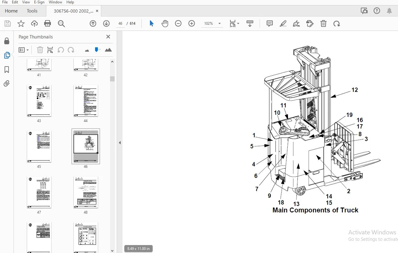
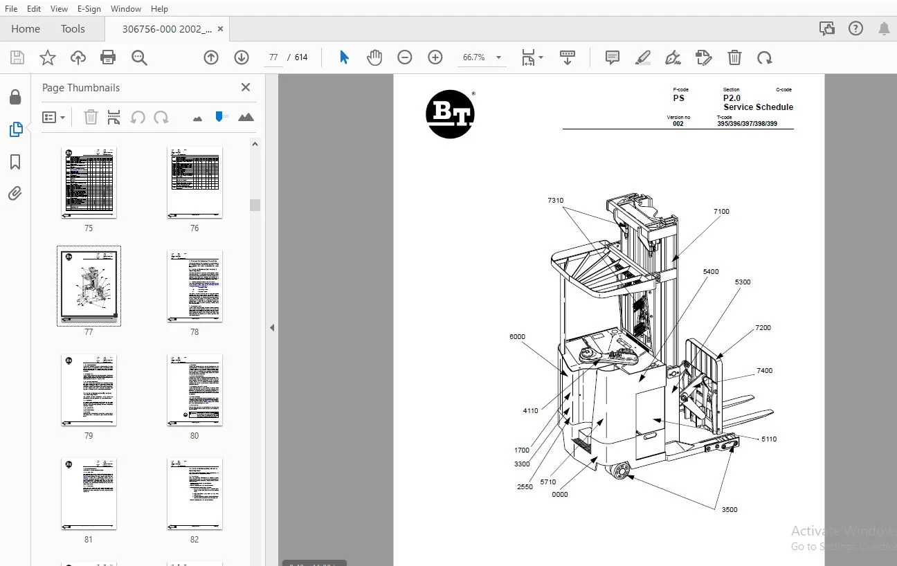
Standard Codes..................................................................  3
Warning Symbols................................................................. 17
	1. Warning Levels........................................................... 17
Prohibitory Symbols............................................................. 18
	1. Ordinance Symbols........................................................ 18
Safety.......................................................................... 19
	1. General Safety........................................................... 19
Battery Safety.................................................................. 23
Static Safety................................................................... 28
Welding Safety.................................................................. 29
Introduction, Service Manual.................................................... 31
Contents, Section M............................................................. 33
	1. Machine Information...................................................... 33
General Product Information..................................................... 35
	1. Presentation of the Rider Trucks......................................... 35
		1.1. Truck Side Views................................................... 35
		1.2. Open Back Compartment.............................................. 36
		1.3. Intended Truck Application......................................... 36
		1.4. Prohibited Truck Application....................................... 37
		1.5. Truck Data......................................................... 37
		1.6. RRX35 Dimensions................................................... 38
		1.7. RRX45 Dimensions................................................... 39
		1.8. RDX30 Dimensions................................................... 40
		1.9. RSX40 Dimensions................................................... 41
		1.10. RSX50 Dimensions.................................................. 42
		1.11. Data Plate........................................................ 43
	2. Main Components.......................................................... 44
Inch (SAE) and Metric Fasteners................................................. 47
	1. Introduction............................................................. 47
	2. Nomenclature, Threads.................................................... 48
	3. Strength Identification.................................................. 49
	4. Conversion of Metric and English Units................................... 57
Technical Service Data.......................................................... 59
Ordering Spare Parts............................................................ 63
Contents, Section P............................................................. 65
	1. Planned Maintenance...................................................... 65
Introduction, Maintenance....................................................... 67
	1. Jacking Truck Off The Floor.............................................. 68
		1.1. Elevate Rear of Truck.............................................. 68
		1.2. Elevate Either Side of Truck....................................... 69
	2. Lubricants............................................................... 70
		2.1. Standard........................................................... 70
		2.2. Corrosion.......................................................... 70
		2.3. Cold Storage....................................................... 70
		2.4. Freezer Storage.................................................... 72
Service Schedule................................................................ 73
	1. Planned Maintenance Schedule............................................. 73
	2. Planned Maintenance Procedures........................................... 78
		2.1. Services Performed Daily or Every 8 Operating Hours................ 78
			2.1.1. Battery Discharge Indicator with slow down................... 78
			2.1.2. Hydraulic System............................................. 78
			2.1.3. Frame/Sheet Metal............................................ 79
			2.1.4. Wheels/Tires................................................. 79
			2.1.5. Functions/Operations......................................... 79
		2.2. Services Performed Monthly or Every 120 Operating Hours............ 79
			2.2.1. Inspection................................................... 79
			2.2.2. Transmission................................................. 79
			2.2.3. Brakes....................................................... 79
			2.2.4. Battery...................................................... 80
			2.2.5. Electrical Connections....................................... 80
			2.2.6. Contactor Tips (NOT Sealed).................................. 80
			2.2.7. Motor Brushes................................................ 80
			2.2.8. Drive Motor.................................................. 80
			2.2.9. Hydraulic Reservoir.......................................... 81
			2.2.10. Frame Lube.................................................. 81
			2.2.11. Pivot Points................................................ 81
		2.3. Services Performed Every 480 or 960 Operating Hours................ 82
			2.3.1. Drive Motor.................................................. 82
		2.4. Services Performed Annually or Every 1440 Operating Hours.......... 83
			2.4.1. Inspection................................................... 83
			2.4.2. Transmission................................................. 83
			2.4.3. Battery...................................................... 83
			2.4.4. Hydraulic System............................................. 84
			2.4.5. Brakes....................................................... 84
			2.4.6. Lift and Carriage Chains..................................... 84
Lubrication Chart............................................................... 85
Oil and Grease Specifications................................................... 86
	1. Approved Oils and Grease................................................. 86
	2. Grease Location Points................................................... 87
	3. Mast Adjustment Points................................................... 88
Contents, Section S............................................................. 89
	1. Service Instructions..................................................... 89
Troubleshooting Guidelines...................................................... 91
	1. General.................................................................. 91
	2. Electrical............................................................... 93
		2.1. Shorts to Frame Test............................................... 93
	3. Hydraulic................................................................ 98
	4. Definitions.............................................................. 99
Chassis.........................................................................101
	1. General..................................................................101
	2. Dash.....................................................................102
		2.1. Removal............................................................102
		2.2. Removal............................................................103
	3. Motor Compartment Door...................................................103
		3.1. Removal............................................................103
		3.2. Installation.......................................................103
	4. Left-Hand Side Panel.....................................................104
		4.1. Removal............................................................104
	5. Operator Compartment Panel...............................................105
		5.1. Removal............................................................105
	6. Main Card Access Panel...................................................105
		6.1. Removal............................................................105
Battery Compartment.............................................................107
	1. Battery Retainer Plates..................................................108
		1.1. Inspection.........................................................108
		1.2. Removal............................................................108
		1.3. Installation.......................................................108
	2. Battery Rollers..........................................................108
		2.1. Inspection.........................................................108
		2.2. Replacement........................................................108
Driver Controls.................................................................109
Brake Pedal, RSX40/RRX35........................................................111
	1. Pedal Removal............................................................112
	2. Pedal Bearing Replacement................................................113
	3. Pedal Adjustment.........................................................113
Brake Pedal, RSX50/RRX45/ RDX30.................................................114
	1. Pedal Removal............................................................115
	2. Pedal Bearing Replacement................................................116
	3. Pedal Adjustment.........................................................116
Overhead Guard..................................................................117
Decals..........................................................................119
	1. Decal with Protective Sheet..............................................119
	2. Decal without Protective Sheet...........................................119
Steering Motor..................................................................123
	1. Removal..................................................................123
	2. Installation.............................................................123
	3. Steering Motor Gear Replacement..........................................124
		3.1. Removal............................................................124
		3.2. Installation.......................................................124
Fan Motor.......................................................................125
	1. Upper Electrical Compartment Fan.........................................125
		1.1. Removal............................................................125
		1.2. Installation.......................................................125
	2. Operator Fan.............................................................126
Motor Maintenance Schedule/Troubleshooting......................................127
	1. General Information......................................................127
	2. Operating Conditions.....................................................127
	3. Troubleshooting..........................................................128
Motor Repair....................................................................135
	1. Disassembly..............................................................135
	2. Motor Inspection.........................................................137
		2.1. External Motor.....................................................137
		2.2. Brush and Commutator...............................................137
		2.3. Bearings...........................................................140
		2.4. Armature Electrical Check..........................................140
		2.5. Frame & Field Service Recommendation...............................141
		2.6. Assembly/Testing...................................................142
Pump Motor......................................................................143
	1. Mounting Points..........................................................143
		1.1. Removal............................................................144
		1.2. Installation.......................................................145
	2. Repair...................................................................147
Drive Motor.....................................................................151
	1. Mounting Points..........................................................151
		1.1. Removal............................................................152
		1.2. Installation.......................................................153
	2. Repair...................................................................154
Transmission....................................................................157
	1. Mounting Points..........................................................157
		1.1. Fluid Changing Procedure...........................................158
		1.2. Removal............................................................158
		1.3. Installation.......................................................159
	2. Repair...................................................................161
	3. Disassemble..............................................................163
	4. Assembly.................................................................167
	5. Axle Sealing Ring........................................................176
		5.1. Disassembly........................................................176
		5.2. Assembly...........................................................177
	6. Leakage..................................................................178
		6.1. Top Cover..........................................................178
		6.2. Lower Cover........................................................179
	7. Wheel Bolt...............................................................180
Electromagnetic Brake...........................................................181
	1. Removal..................................................................181
	2. Installation.............................................................183
	3. Adjustments..............................................................184
	4. Coil Check On Brake......................................................185
	5. Electromagnetic Brake, Armature and Magnetic Coil........................185
		5.1. Removal............................................................185
		5.2. Installation.......................................................186
	6. Brake Friction Plate.....................................................186
		6.1. Inspection.........................................................186
		6.2. Replacement........................................................186
Drive Wheel.....................................................................187
	1. Removal..................................................................188
	2. Installation.............................................................188
	3. Tire Pressing Procedure..................................................189
Non-Braking Caster Wheel, RRX35/ RSX40..........................................191
	1. Caster Pivot.............................................................193
		1.1. Removal............................................................193
	2. Thrust Bearing...........................................................195
		2.1. Removal............................................................195
		2.2. Installation.......................................................196
	3. Caster Springs...........................................................197
		3.1. Adjustment.........................................................197
		3.2. Removal............................................................197
		3.3. Installation.......................................................198
	4. Caster Stops.............................................................199
		4.1. Adjustment.........................................................199
Non-Braking Caster Assembly, RRX35/RSX40........................................201
	1. Removal..................................................................202
	2. Installation.............................................................202
Braking Caster Wheel, RRX45/RDX30/ RSX50........................................203
	1. Removal..................................................................205
		1.1. Caster Brake Adjustment............................................205
Braking Caster Assembly, RRX45/ RDX30/RSX50.....................................207
	1. Removal..................................................................209
	2. Installation.............................................................210
Load Wheels, Sizes 4 X 3, 5 X 4, and 5 X 3......................................211
	1. Removal..................................................................213
	2. Installation.............................................................214
Load Wheels, Size 10.5 X 3.5....................................................215
	1. Removal..................................................................216
	2. Installation.............................................................216
Steering Arm / Wheel / Lever....................................................217
	1. Control Pod..............................................................219
		1.1. Removal............................................................219
		1.2. Installation.......................................................219
	2. Steering Wheel...........................................................220
		2.1. Removal............................................................220
		2.2. Installation.......................................................220
	3. Steering Tach............................................................221
		3.1. Removal............................................................221
		3.2. Installation.......................................................221
Steering Bearing................................................................223
	1. Removal..................................................................224
	2. Installation.............................................................224
Electrical Functions............................................................225
	1. General..................................................................225
		1.1. Directional/Speed Control Lever....................................225
		1.2. Main Electronic Card...............................................226
	2. Start Up.................................................................229
	3. Steering Components......................................................233
		3.1. Steering System....................................................233
		3.2. Wheel Direction Sensors............................................237
	4. Brake Release............................................................239
	5. Direction Selection......................................................241
	6. Travel Request, Forks First..............................................243
	7. Travel Request, Forks Trailing...........................................247
	8. Plug Braking.............................................................252
		8.1. Directional/Speed Control Lever Method.............................252
		8.2. Brake Pedal Method.................................................253
	9. 12-Volt Power Supply.....................................................256
	10. 7.35-Volt Power Supplies................................................257
	11. Limit Switches..........................................................260
		11.1. Truck Travel Speed Limiting.......................................260
		11.2. Mast Staging Speed Limiting.......................................262
	12. Height Indicator........................................................264
		12.1. Height Preset Selector............................................265
	13. Drive Motor Brush Wear Indicator Switches...............................266
	14. Pump Motor Brush Indicator Switch.......................................267
	15. Safety Check............................................................268
	16. Shunt Power Cable.......................................................270
Electrical Symbols..............................................................277
Electrical Schematics (Serial numbers 27163000-28105000)........................279
	1. Circuit Diagram 1(11)....................................................279
	2. Circuit Diagram 2(11)....................................................280
	3. Circuit Diagram 3(11)....................................................281
	4. Circuit Diagram 4(11)....................................................282
	5. Circuit Diagram 5(11)....................................................283
	6. Circuit Diagram 6(11)....................................................284
	7. Circuit Diagram 7(11)....................................................285
	8. Circuit Diagram 8(11)....................................................286
	9. Circuit Diagram 9(11)....................................................287
	10. Circuit Diagram 10(11)..................................................288
	11. Circuit Diagram 11(11)..................................................289
Electrical Schematics (Serial numbers 28105001-28126000)........................291
	1. Circuit Diagram 1(12)....................................................291
	2. Circuit Diagram 2(12)....................................................292
	3. Circuit Diagram 3(12)....................................................293
	4. Circuit Diagram 4(12)....................................................294
	5. Circuit Diagram 5(12)....................................................295
	6. Circuit Diagram 6(12)....................................................296
	7. Circuit Diagram 7(12)....................................................297
	8. Circuit Diagram 8(12)....................................................298
	9. Circuit Diagram 9(12)....................................................299
	10. Circuit Diagram 10(12)..................................................300
	11. Circuit Diagram 11(12)..................................................301
	12. Circuit Diagram 12(12)..................................................302
Electrical Schematics (Serial numbers 28126001-31285000)........................303
	1. Circuit Diagram 1(12)....................................................303
	2. Circuit Diagram 2(12)....................................................304
	3. Circuit Diagram 3(12)....................................................305
	4. Circuit Diagram 4(12)....................................................306
	5. Circuit Diagram 5(12)....................................................307
	6. Circuit Diagram 6(12)....................................................308
	7. Circuit Diagram 7(12)....................................................309
	8. Circuit Diagram 8(12)....................................................310
	9. Circuit Diagram 9(12)....................................................311
	10. Circuit Diagram 10(12)..................................................312
	11. Circuit Diagram 11(12)..................................................313
	12. Circuit Diagram 12(12)..................................................314
Electrical Schematics (Serial numbers 31285001-UP)..............................315
	1. Circuit Diagram 1(12)....................................................315
	2. Circuit Diagram 2(12)....................................................316
	3. Circuit Diagram 3(12)....................................................317
	4. Circuit Diagram 4(12)....................................................318
	5. Circuit Diagram 5(12)....................................................319
	6. Circuit Diagram 6(12)....................................................320
	7. Circuit Diagram 7(12)....................................................321
	8. Circuit Diagram 8(12)....................................................322
	9. Circuit Diagram 9(12)....................................................323
	10. Circuit Diagram 10(12)..................................................324
	11. Circuit Diagram 11(12)..................................................325
	12. Circuit Diagram 12(12)..................................................326
Battery.........................................................................327
	1. Removal..................................................................327
	2. Installation.............................................................327
	3. Battery Maintenance......................................................328
		3.1. Battery Inspection and Care........................................328
		3.2. Battery Exterior Cleaning..........................................329
		3.3. Charging...........................................................329
	4. Storage..................................................................330
	5. Battery History Record...................................................330
Light Assemblies................................................................331
	1. Overhead Guard Lights (Option)...........................................331
		1.1. Removal............................................................331
		1.2. Installation.......................................................331
	2. Warning Lights (Option)..................................................332
		2.1. Removal............................................................332
		2.2. Installation.......................................................333
	3. Working Lights (Option)..................................................333
		3.1. Removal............................................................333
		3.2. Installation.......................................................333
	4. Travel Alarm (Option)....................................................334
		4.1. Removal............................................................334
		4.2. Installation.......................................................334
	5. Operator Fan (Option)....................................................335
		5.1. Removal............................................................336
		5.2. Installation.......................................................336
Horn............................................................................337
	1. Removal..................................................................337
	2. Installation.............................................................337
Start/Stop Switches.............................................................339
	1. General..................................................................339
		1.1. Test/Inspection....................................................339
	2. Key Switch (S17).........................................................339
		2.1. Inspection.........................................................339
		2.2. Removal............................................................340
		2.3. Installation.......................................................340
	3. Emergency Disconnect Switch (S21)........................................341
		3.1. Inspection.........................................................341
		3.2. Removal............................................................341
		3.3. Installation.......................................................342
Battery Connector...............................................................343
	1. Location.................................................................343
	2. Inspection...............................................................343
	3. Installation.............................................................344
Mast Switch (S31)...............................................................345
	1. General..................................................................345
		1.1. Test/Inspection....................................................345
		1.2. Adjustment.........................................................347
		1.3. Removal............................................................348
		1.4. Installation.......................................................348
Control Cable and Harness.......................................................349
	1. Fuses....................................................................349
	2. Wiring...................................................................350
		2.1. Harness............................................................350
		2.2. Power Cables.......................................................351
Contactors......................................................................353
	1. General..................................................................353
		1.1. Resistance Testing.................................................353
		1.2. Contactor Tip Inspection...........................................353
	2. Direction Contactors.....................................................354
		2.1. Removal............................................................355
		2.2. Installation.......................................................355
	3. Lift Bypass Contactor (RRX45/RSX50/RDX30)................................356
		3.1. Removal............................................................357
		3.2. Installation.......................................................357
	4. Main Contactor...........................................................358
		4.1. Removal............................................................359
		4.2. Installation.......................................................359
Transistor Panel (Drive)........................................................361
	1. Motor Connections........................................................362
Transistor Panel (Lift).........................................................363
	2. Circuit Check, Drive Only................................................365
Micro Switches..................................................................367
	1. General..................................................................367
	2. Lift Limit Override Switch (S33) Optional................................368
		2.1. Removal............................................................368
		2.2. Installation.......................................................368
	3. Optional Light and Fan Switches (S96, S97 and S99).......................369
		3.1. Removal............................................................369
		3.2. Installation.......................................................369
Main Electronic Card............................................................371
	1. Connectivity to Truck....................................................371
	2. Transistor Controller Replacement........................................372
	3. Removal..................................................................376
	4. Installation.............................................................376
	5. Display..................................................................382
	6. Time.....................................................................383
	7. Effect on Truck..........................................................383
	8. Running time.............................................................384
	9. RV2 Adjustment Procedure.................................................384
	10. Adjustment Procedures for Setting Brake Switch and Brake Transducer.....385
	11. Battery Discharge Indicator Parameter Adjustment........................386
	12. A5 Jumper Harness Kit Installation (Serial numbers 28126000 - below)....392
	13. Warning\Caution Codes...................................................395
	14. Error Codes.............................................................397
		14.1. E102 Troubleshooting Procedures...................................399
			14.1.1. Power Circuit Checks........................................399
			14.1.2. Reference Circuit Value Checks (LED #4).....................401
	15. Programming Parameter...................................................403
Switches and Sensors............................................................413
	1. General..................................................................413
		1.1. Test/Inspection....................................................413
	2. Platform (Right Foot) Switch (S108)......................................413
		2.1. Removal............................................................414
		2.2. Installation.......................................................414
	3. Staging Switch (S45).....................................................415
		3.1. Adjustment.........................................................416
		3.2. Removal............................................................416
		3.3. Installation.......................................................416
	4. Wheel Direction Sensor...................................................417
		4.1. Adjustment.........................................................417
		4.2. Removal............................................................418
		4.3. Installation.......................................................418
	5. Steer Proximity Sensors A and B (S66 and S67)............................419
		5.1. Adjustment.........................................................419
		5.2. Removal............................................................420
		5.3. Installation.......................................................420
	6. Drive Motor Speed(S64)/Direction Sensors (S125)..........................421
		6.1. Removal............................................................421
		6.2. Installation.......................................................422
Hydraulic System................................................................423
	1. Operation................................................................423
		1.1. Supply.............................................................425
		1.2. Lifting............................................................426
		1.3. Lowering...........................................................427
		1.4. Reach..............................................................429
		1.5. Retract............................................................431
		1.6. Reach Relief (RRX35 Only)..........................................432
		1.7. Reach Impact (RRX35 Only)..........................................433
		1.8. Tilt Up............................................................435
		1.9. Tilt Down..........................................................437
		1.10. Side Shifting Right...............................................439
		1.11. Side Shifting Left................................................441
	2. RRX35 Hydraulic Schematic................................................444
	3. RRX45 Hydraulic Schematic................................................445
	4. RDX30 Hydraulic Schematic................................................446
	5. RSX40 Hydraulic Schematic................................................447
	6. RSX50 Hydraulic Schematic................................................448
Hydraulic Fluid.................................................................449
	1. Hydraulic Fluid Selection................................................449
	2. Changing Hydraulic System Fluid..........................................449
	3. System Draining..........................................................450
	4. Refilling System.........................................................451
	5. Bleeding Hydraulic System................................................452
Hydraulic Tank..................................................................454
	1. Removal..................................................................455
	2. Installation.............................................................456
Hydraulic Filter Assembly.......................................................458
	1. Hydraulic Filter.........................................................459
		1.1. Removal............................................................459
		1.2. Installation.......................................................459
	2. Hydraulic Filter Adapter.................................................460
		2.1. Removal............................................................460
		2.2. Installation.......................................................460
Hydraulic Pump..................................................................462
	1. Removal..................................................................462
	2. Repair...................................................................462
Control Valve...................................................................463
	1. Removal..................................................................463
	2. Installation.............................................................463
Control Valve Assembly..........................................................468
	3. Repair...................................................................470
		3.1. Proportional Pre-Pressure Reducing Valve...........................470
		3.2. Valve Assembly SWR14...............................................470
		3.3. Pressure Limiting Valve Assembly...................................471
		3.4. Setting Lift/Auxiliary Pressure Relief with a Rated Load...........471
		3.5. Hydraulic Lowering Rate Adjustment.................................472
		3.6. Recondition Seal Kit...............................................473
Staging Cylinder, Three Stage Mast..............................................475
	1. Bearing Removal..........................................................476
	2. Disassembly..............................................................477
	3. Assembly.................................................................477
	4. Installation.............................................................477
Freelift Cylinder, Three Stage Mast.............................................479
	1. Removal..................................................................481
	2. Disassembly..............................................................482
	3. Assembly.................................................................482
	4. Installation.............................................................482
Reach Cylinder Assembly.........................................................483
	1. Removal..................................................................485
	2. Disassembly..............................................................486
	3. Inspection...............................................................487
	4. Assembly.................................................................488
	5. Installation.............................................................489
Tilt Cylinder Assembly, RRX35/RSX40/ RSX50......................................491
	1. Removal..................................................................492
	2. Disassembly..............................................................493
	3. Inspection...............................................................494
	4. Assembly.................................................................495
	5. Installation.............................................................496
Tilt Cylinder Assembly, RRX45/RDX30.............................................497
	1. Removal..................................................................499
	2. Disassembly..............................................................500
	3. Inspection...............................................................501
	4. Assembly.................................................................502
	5. Installation.............................................................503
Mast, 3 Stage...................................................................505
	1. Shimming Carriage with Mast on Truck.....................................509
	2. Three Stage Mast.........................................................511
		2.1. Removal............................................................511
		2.2. Disassembly........................................................512
		2.3. Assembly...........................................................513
		2.4. Installation.......................................................515
	3. Lift Chain...............................................................516
		3.1. Lift Chain Adjustment..............................................516
		3.2. Lift Chain Maintenance.............................................516
		3.3. Lift Chain Inspection..............................................516
			3.3.1. Wear.........................................................517
			3.3.2. Rust and Corrosion...........................................517
			3.3.3. Cracked Plates...............................................518
			3.3.4. Protruding or Turned Pins....................................520
			3.3.5. Chain Side Wear..............................................521
			3.3.6. Chain Anchors and Sheaves....................................521
			3.3.7. Lift Chain Lubrication.......................................521
		3.4. Lift Chain Replacement.............................................523
Lifting Gear (Crosshead)........................................................525
	1. Lifting Gear Repair......................................................527
		1.1. Removal............................................................527
		1.2. Disassembly........................................................528
		1.3. Assembly...........................................................528
		1.4. Installation.......................................................528
Sideshifter, RRX35/45/RDX30.....................................................529
	1. Mounting Instructions....................................................531
		1.1. Installation.......................................................531
	2. Operation and Maintenance................................................532
		2.1. Lower Slides.......................................................532
		2.2. Upper Slides.......................................................533
		2.3. Cylinder...........................................................533
Sideshifter, RRX35/45/RSX40/50/RDX30............................................535
	1. Mounting Instructions....................................................537
		1.1. Installation.......................................................537
	2. Operation................................................................538
	3. Maintenance..............................................................538
		3.1. Carriage Removal...................................................539
		3.2. Upper Pad Replacement..............................................539
		3.3. Lower Pad Replacement..............................................540
		3.4. Cylinder...........................................................541
	4. Troubleshooting..........................................................542
		4.1. No Sideshifting....................................................542
		4.2. Sideshifting Very Slow.............................................542
		4.3. Irregular Sideshifting.............................................542
Single Reach, RRX35.............................................................543
	1. Maintenance..............................................................549
		1.1. Inspection.........................................................549
		1.2. Adjustment.........................................................550
	2. Reach Repair.............................................................554
		2.1. Removal............................................................554
		2.1. Disassembly........................................................554
			2.1.1. Front Frame Removal..........................................554
			2.1.2. Outer Arm Removal............................................555
			2.1.3. Inner Arm Removal............................................555
			2.1.4. Rear Frame Removal...........................................555
			2.1.5. Reach Cylinder Removal.......................................556
		2.2. Assembly...........................................................556
			2.2.1. Reach Cylinder Installation..................................556
			2.2.2. Rear Frame Installation......................................556
			2.2.3. Inner Arm Installation.......................................557
			2.2.4. Outer Arm Installation.......................................557
			2.2.5. Front Frame Installation.....................................558
	3. Carriage Bumpers.........................................................558
		3.1. Reach Adjustment...................................................558
	4. Fork Carriage Pivot Pins.................................................560
	5. Carriage Roller Bearings.................................................560
		5.1. Removal............................................................560
		5.2. Installation.......................................................560
Single Reach, RRX45.............................................................561
	1. Maintenance..............................................................561
	2. Reach Repair.............................................................569
		2.1. Disassembly........................................................569
			2.1.1. Forward Frame Removal........................................569
			2.1.2. Outer Arm Removal............................................569
			2.1.3. Inner Arm Removal............................................570
			2.1.4. Rear Frame Removal...........................................570
			2.1.5. Reach Cylinder Removal.......................................571
		2.2. Assembly...........................................................571
			2.2.1. Reach Cylinder Installation..................................571
			2.2.2. Rear Frame Installation......................................571
			2.2.3. Inner Arm Installation.......................................572
			2.2.4. Outer Arm Installation.......................................572
			2.2.5. Front Frame Installation.....................................573
	3. Fork Carriage Pivot Pins.................................................573
	4. Carriage Roller Bearings.................................................574
		4.1. Removal............................................................574
		4.2. Installation.......................................................574
Double Reach Mechanism, RDX30...................................................575
	1...........................................................................576
	Rod.........................................................................576
	24..........................................................................576
	Bearing.....................................................................576
	46..........................................................................576
	Bearing, 3 stage............................................................576
	2...........................................................................576
	Arm.........................................................................576
	25..........................................................................576
	Ring, Nilos.................................................................576
	47..........................................................................576
	Cap, bearing................................................................576
	3...........................................................................576
	Bearing, thrust.............................................................576
	26..........................................................................576
	Set, bearing................................................................576
	48..........................................................................576
	Screw.......................................................................576
	4...........................................................................576
	Bearing.....................................................................576
	27..........................................................................576
	Spacer......................................................................576
	49..........................................................................576
	Bearing.....................................................................576
	5...........................................................................576
	Arm.........................................................................576
	28..........................................................................576
	Tilt cylinder assembly......................................................576
	50..........................................................................576
	Cap.........................................................................576
	6...........................................................................576
	Pin, roll...................................................................576
	29..........................................................................576
	Screw.......................................................................576
	51..........................................................................576
	Screw.......................................................................576
	7...........................................................................576
	Pin.........................................................................576
	30..........................................................................576
	Pin.........................................................................576
	52..........................................................................576
	Block, bumper...............................................................576
	8...........................................................................576
	Frame, fork.................................................................576
	31..........................................................................576
	Screw, set..................................................................576
	53..........................................................................576
	Bumper......................................................................576
	9...........................................................................576
	Screw.......................................................................576
	32..........................................................................576
	Arm.........................................................................576
	54..........................................................................576
	Screw, socket head..........................................................576
	10..........................................................................576
	Frame, forward..............................................................576
	33..........................................................................576
	Nut, lock...................................................................576
	55..........................................................................576
	Screw, socket head..........................................................576
	11..........................................................................576
	Bearing.....................................................................576
	34..........................................................................576
	Arm.........................................................................576
	56..........................................................................576
	Lockwasher..................................................................576
	12..........................................................................576
	Shim........................................................................576
	35..........................................................................576
	Arm.........................................................................576
	57..........................................................................576
	Bushing.....................................................................576
	13..........................................................................576
	Arm.........................................................................576
	36..........................................................................576
	Pin.........................................................................576
	58..........................................................................576
	Bracket.....................................................................576
	14..........................................................................576
	Nut.........................................................................576
	37..........................................................................576
	Screw.......................................................................576
	59..........................................................................576
	Shield......................................................................576
	15..........................................................................576
	Pin, cotter.................................................................576
	38..........................................................................576
	Reach cylinder assembly.....................................................576
	60..........................................................................576
	Screw, cap..................................................................576
	16..........................................................................576
	Nut, slotted................................................................576
	39..........................................................................576
	Fitting, grease.............................................................576
	61..........................................................................576
	Manifold....................................................................576
	17..........................................................................576
	Washer......................................................................576
	40..........................................................................576
	Frame, rear.................................................................576
	62..........................................................................576
	Control valve...............................................................576
	18..........................................................................576
	Ring, Nilos.................................................................576
	41..........................................................................576
	Washer, shim................................................................576
	63..........................................................................576
	Cover.......................................................................576
	19..........................................................................576
	Cone, bearing...............................................................576
	42..........................................................................576
	Screw.......................................................................576
	64..........................................................................576
	Screw, cap..................................................................576
	20..........................................................................576
	Race, bearing...............................................................576
	43..........................................................................576
	Bar, wear...................................................................576
	65..........................................................................576
	Nut, flanged................................................................576
	21..........................................................................576
	Ring, retainer..............................................................576
	44..........................................................................576
	Shim........................................................................576
	66..........................................................................576
	Washer......................................................................576
	22..........................................................................576
	Shim........................................................................576
	45..........................................................................576
	Shim........................................................................576
	67..........................................................................576
	Shim........................................................................576
	23..........................................................................576
	Arm.........................................................................576
	1. Theory of Operation......................................................577
	2. Maintenance..............................................................577
	3. Troubleshooting..........................................................577
	4. Repair...................................................................577
	5. Rebuild..................................................................577
Forks...........................................................................579
	1. Removal..................................................................581
	2. Inspection...............................................................581
	3. Installation.............................................................582
Load Indicator..................................................................583
Load Indicator..................................................................585
	1. Pulse Sensor.............................................................587
		1.1. Repair.............................................................587
		1.2. Cable..............................................................587
			1.2.1. Removal......................................................587
			1.2.2. Installation.................................................587
		1.3. Pulley.............................................................588
			1.3.1. Removal......................................................588
Height Indicator and Preset Selector............................................589
	1. General..................................................................590
	2. Operation................................................................590
	3. Preset Height............................................................591
	4. Display..................................................................592
	5. Display Symbols Description..............................................593
	6. Programming..............................................................594
		6.1. Programming a Level................................................594
			6.1.1. Collection Level.............................................594
			6.1.2. Leaving Level................................................594
		6.2. Erasing Programmed Levels..........................................595
			6.2.1. Automatic Operations.........................................595
			6.2.2. Collecting a Load............................................595
			6.2.3. Leaving a Load...............................................596
		6.3. Parameters.........................................................597
Load Backrest...................................................................603
	1. Removal..................................................................606
	2. Installation.............................................................606
	A...........................................................................607
	B...........................................................................607
	C...........................................................................607
	D...........................................................................608
	E...........................................................................608
	F...........................................................................608
	G...........................................................................608
	H...........................................................................608
	I...........................................................................609
	J...........................................................................609
	K...........................................................................609
	L...........................................................................609
	M...........................................................................609
	N...........................................................................609
	O...........................................................................609
	P...........................................................................609
	R...........................................................................610
	S...........................................................................610
	T...........................................................................610
	V...........................................................................611
	W...........................................................................611
DESCRIPTION:
BT FORKLIFT RRX35/45, RDX30, RSX40/50 MASTER SERVICE MANUAL 306756-000 2002_February – PDF DOWNLOAD
- The information in this Service Manual covers models RRX35, RRX45, RDX30, RSX40, and RSX50.
- Federal and State laws require that operators be completely trained in the safe operation of trucks in accordance with OSHA regulation 1910.178.
- An Operator’s Manual is sent with every BT Prime-Mover lift truck when it is manufactured.
- This Service Manual is not a training manual. The information contained in this service manual is intended as a guide to help trained, qualified, and authorized technicians safely service the truck.
- The Service Manual is divided into four separate sections, which cover needed information for servicing the truck types.
- The main subject for each of the sections are as described below.
S.S 06/01/2025