BT IXION S10 S12 Stacker Service Manual Electric Forklift Repair Guide PDF
Original price was: $85.00.$26.95Current price is: $26.95.
Official factory service manual for BT IXION S10, S12, and S12S electric walkie stackers. Comprehensive technical documentation includes specifications, preventive maintenance schedules, lubrication procedures, electric drive motor service, hydraulic system diagrams, lift chain maintenance, Curtis controller diagnostics, fault codes, electrical schematics, support arm chassis repair, electromagnetic brake service, steering adjustments, and battery charger specifications for professional material handling technicians.
Description
BT IXION S10 S12 Stacker Service Manual Electric Forklift Repair Guide PDF DOWNLOAD
DESCRIPTION
This comprehensive BT IXION S10/S12/S12S Service Manual (Order Number 202178-040, Version 001) provides complete technical documentation for servicing and repairing BT Industries’ electric walkie stacker lineup. This professional-grade manual is essential for certified technicians, warehouse maintenance professionals, forklift fleet service departments, and authorized BT dealer service centers working on these popular material handling equipment models.
Models Covered
This service manual provides complete technical information for the following BT IXION electric walkie stacker models:
Model S10:
- Drive Motor: TSL140S-DS20, 1.0 kW output
- Duty Cycle: S2, 60 minutes
- Compact stacker for light-duty applications
Model S12:
- Drive Motor: TSL140S-DS30, 1.2 kW output
- Duty Cycle: S2, 60 minutes
- Standard capacity electric stacker
Model S12S:
- Drive Motor: TSL140S-DS30, 1.2 kW output
- Duty Cycle: S2, 60 minutes
- Enhanced specification stacker
Serial Number Coverage
Valid from Serial Number: 425801AA- and above
T-Code: 700-701
C-Code: 700, 701
Document Information
Order Number: 202178-040
Issued Date: January 7, 2002
Current Version: 001 (December 2, 2002)
Total Pages: 106 pages
Format: A4 size (595 x 841 pts)
Copyright: BT Industries AB / BT Europe AB
Approved by: L-G Andersson
Technical Data
Drive Motor Specifications (All Models):
Type: TSL140S-DS20 (S10), TSL140S-DS30 (S12/S12S)
Power Output:
- S10: 1.0 kW
- S12/S12S: 1.2 kW
Duty Cycle: S2, 60 minutes continuous operation
Carbon Brushes:
- Minimum carbon brush length: 13 mm
- Nominal commutator diameter: 50 mm
- Minimum commutator diameter: 47 mm
Electrical Specifications:
- Shunt field winding resistance at 25°C: 0.49 Ω
- Armature winding resistance at 24°C: 0.0156 Ω
- Insulation resistance (winding to chassis): ≥1 MΩ
Wheel Specifications:
Drive Wheels (All Models):
- Diameter: 215 x 70 mm
- Wheel bolt tightening torque: 65 Nm
- S10 axle pressure without load: 340 kg
- S10 axle pressure at rated load: 340 kg
- S12 axle pressure without load: 345 kg
- S12 axle pressure at rated load: 345 kg
- S12S axle pressure without load: 690 kg
- S12S axle pressure at rated load: 735 kg
Support Arm Wheels:
- S10/S12: Dia 80 x 95 mm
- S12S: Dia 100 x 75 mm
- S10 axle pressure without load: 2 x 230 kg (240 kg)
- S10 axle pressure at rated load: 2 x 1100 kg (240 kg)
- S12 axle pressure without load: 2 x 270 kg (240 kg)
- S12 axle pressure at rated load: 2 x 1350 kg (240 kg)
- S12S axle pressure without load: 2 x 355 kg (240 kg)
- S12S axle pressure at rated load: 2 x 1510 kg (240 kg)
Support Castors:
- Diameter: 125 x 40 mm
Section: Introduction Maintenance
1. Safety Regulations with Maintenance Work:
- Comprehensive safety requirements for service personnel
- Personal protective equipment specifications
- Lockout/tagout procedures
- Safe working practices around electrical and hydraulic systems
- Emergency procedures
2. Cleaning and Washing:
- Approved cleaning methods and materials
- Prohibited cleaning agents
- Component-specific cleaning procedures
- Preventive corrosion protection
3. Safe Lifting:
- Proper lifting points identification
- Equipment capacity requirements
- Lifting procedure safety protocols
- Component weight specifications
- Crane and hoist usage guidelines
Section: Preventive Maintenance
1. Maintenance Schedule:
Complete interval-based maintenance program covering:
- Daily inspection procedures
- Weekly service requirements
- Monthly maintenance tasks
- Quarterly inspection points
- Annual service procedures
- Major overhaul intervals
Scheduled Maintenance Tasks:
- Visual inspections
- Fluid level checks
- Battery maintenance
- Electrical system inspection
- Hydraulic system verification
- Lift chain inspection and adjustment
- Brake system testing
- Steering mechanism checks
- Tire and wheel inspection
- Safety device testing
2. Lubrication Schedule:
Comprehensive lubrication program specifying:
- Lubrication points identification
- Grease type and quantity specifications
- Lubrication intervals
- Special lubrication procedures
- Seasonal lubrication adjustments
Section: Oil and Grease Specification
- Approved lubricant brands and specifications
- Hydraulic oil specifications and viscosity grades
- Gear oil requirements
- Grease types for various applications
- Environmental considerations
- Fluid disposal procedures
Section: Tools
1. Super Seal Connectors:
- Special connector removal and installation tools
- Torque specifications for electrical connections
- Connector inspection procedures
- Replacement procedures
- Terminal crimping specifications
Required Special Tools:
- Bearing pullers and installers
- Torque wrenches (various ranges)
- Hydraulic pressure test equipment
- Electrical testing equipment
- Alignment tools
Section: Support Arm Chassis
1. General:
- Support arm construction and design
- Load-bearing specifications
- Structural integrity inspection
2. Main Components:
- Support arm assembly breakdown
- Wheel mounting systems
- Adjustment mechanisms
- Pivot points and bearings
3. Maintenance:
- Regular inspection procedures
- Wear point identification
- Bushing and bearing service
- Structural damage assessment
4. Adjustment of Support Arm Width:
- Width adjustment procedure
- Load capacity considerations
- Safety verification after adjustment
- Locking mechanism service
5. Exchange of Support Arms:
- Complete removal procedure
- Installation of replacement arms
- Alignment verification
- Post-installation testing
Section: Electric Drive Motor
1. Component Parts:
- Motor assembly exploded view
- Armature and field winding identification
- Bearing specifications
- Brush holder assembly
- Commutator details
- Cooling fan components
2. Service/Repairs:
- Motor removal and installation procedures
- Carbon brush inspection and replacement
- Commutator inspection and resurfacing
- Bearing replacement procedures
- Armature testing procedures
- Field winding testing
- Insulation resistance testing
- Motor performance testing
3. Technical Data:
- Complete electrical specifications
- Torque specifications for motor mounting
- Clearance measurements
- Tolerance specifications
Section: Drive Unit/Gear
1. Component Parts:
- Gearbox assembly exploded diagrams
- Gear specifications and ratios
- Shaft and bearing details
- Seal and gasket identification
- Oil level sight glass location
2. Leakage from Top Cover:
- Leak source identification
- Gasket and seal replacement
- Bolt torque specifications
- Oil level verification
3. Changing of Drive Shaft’s Sealing Ring:
- Seal removal procedure
- Shaft inspection for damage
- New seal installation technique
- Oil replenishment procedure
Section: Electro Magnetic Brake
1. Main Components of the Brake:
- Brake assembly construction
- Electromagnetic coil specifications
- Friction disc details
- Spring and adjustment mechanisms
- Electrical connections
2. Maintenance:
- Brake adjustment procedures
- Friction material inspection
- Coil resistance testing
- Gap measurement and adjustment
- Brake torque testing
- Release mechanism verification
- Emergency brake release procedure
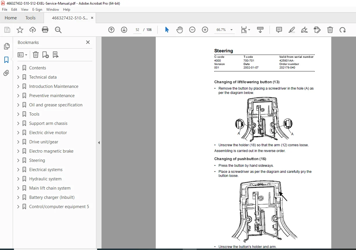
Section: Steering
1. Component Parts, Tiller Arm:
- Tiller arm assembly breakdown
- Steering column components
- Control handle assemblies
- Cable and linkage identification
- Position sensors
2. Adjustments:
- Tiller arm height adjustment
- Steering sensitivity adjustment
- Control handle positioning
- Cable tension adjustment
- Micro-switch adjustment
- Safety interlock verification
3. Tiller Arm Handle:
- Handle grip replacement
- Switch and button service
- Emergency controls testing
- Cable routing and protection
Section: Electrical Systems
1. Electrical Parts:
- Complete component listing
- Part numbers and specifications
- Location identification
- Replacement procedures
2. List of Symbols and Electrical Wiring Diagram:
- Comprehensive electrical schematic
- Wire color coding standards
- Connector identification
- Fuse and relay locations
- Circuit protection specifications
- Grounding points
3. Functional Description:
- Circuit operation explanation
- Safety system logic
- Control system operation
- Emergency stop function
- Battery management system
- Curtis controller integration
4. Hour Meter:
- Hour meter location and access
- Reading and resetting procedures
- Maintenance interval tracking
5. Fault Codes:
Complete Curtis controller diagnostic fault code database:
- Fault code definitions
- Probable causes for each code
- Troubleshooting procedures
- Resolution steps
- Code clearing procedures
Common Fault Codes Covered:
- Motor and armature faults
- Controller temperature issues
- Battery voltage problems
- Throttle sensor faults
- Brake circuit errors
- Contactor failures
- Communication errors
6. Parameters:
Curtis controller parameter programming:
- Adjustable parameter listing
- Factory default settings
- Parameter modification procedures
- Performance tuning guidelines
- Speed control parameters
- Acceleration and deceleration settings
- Regenerative braking parameters
7. Part Numbers:
- Electrical component part number cross-reference
- Supersession information
- Compatibility notes
8. Transistor Panel:
- MOSFET/transistor panel construction
- Heat sink specifications
- Thermal protection systems
- Testing procedures
- Replacement procedures
9. Diagnostic and Troubleshooting:
- Systematic troubleshooting flowcharts
- Electrical testing procedures
- Voltage and current measurements
- Controller diagnostic modes
- Component isolation testing
10. Technical Specifications – Curtis 1243:
- Complete Curtis 1243 controller specifications
- Input/output specifications
- Environmental specifications
- Electrical ratings
- Communication protocols
Section: Hydraulic System
1. Hydraulic Diagram and Components:
Complete hydraulic circuit documentation:
- Full hydraulic schematic diagram
- Component identification and location
- Hydraulic pump specifications
- Control valve details
- Cylinder specifications
- Hose and fitting identification
- Pressure relief valve settings
- Flow control valve adjustments
Hydraulic Components:
- Hydraulic power unit
- Lift cylinders
- Lowering valves
- Flow control valves
- Pressure relief valves
- Hydraulic reservoir
- Filters and strainers
- Hoses and fittings
Service Procedures:
- Hydraulic oil specification and capacity
- Oil change procedures
- Filter replacement intervals
- Pressure testing procedures
- Cylinder seal replacement
- Valve adjustment and calibration
- Leak detection and repair
- System bleeding procedures
Section: Main Lift Chain System
2. General:
- Lift chain system overview
- Chain construction and specifications
- Sprocket details
- Chain guides and tensioners
3. Checking the Chain Setting:
- Chain tension measurement
- Adjustment procedures
- Safety lock mechanisms
- Post-adjustment verification
4. Chain Inspection:
Comprehensive chain inspection procedures:
- Visual inspection criteria
- Link wear measurement
- Pin and bushing wear limits
- Roller wear assessment
- Plate elongation measurement
- Crack detection methods
- Replacement criteria
Wear Limits and Specifications:
- Maximum allowable elongation
- Pin wear limits
- Roller diameter limits
- Plate thickness minimums
5. Cleaning:
- Chain cleaning methods
- Approved cleaning solutions
- Debris removal techniques
- Drying procedures
6. Lubrication:
- Lubricant specification
- Application methods
- Lubrication intervals
- Coverage requirements
- Excess lubricant removal
Section: Battery Charger (Inbuilt)
1. Battery Charger Specifications:
- Charger type and capacity
- Input voltage requirements
- Output voltage and current
- Charge cycle specifications
- Safety features and protections
Charger Operation:
- Charging procedure
- Charge cycle stages
- Indicator light meanings
- Emergency stop function
- Cooling system
Maintenance:
- Charger inspection procedures
- Connector maintenance
- Cable inspection
- Safety device testing
- Troubleshooting charging issues
Key Features & Technical Highlights
✓ Three Model Coverage – S10, S12, and S12S in single comprehensive manual
✓ Complete Maintenance Schedules – Daily through annual service intervals
✓ Curtis 1243 Controller – Full diagnostic procedures and fault codes
✓ Electric Drive Motor – Complete specifications and rebuild procedures
✓ Hydraulic System – Detailed schematics and component service
✓ Lift Chain Maintenance – Inspection criteria and wear limits
✓ Electrical Schematics – Complete wiring diagrams with troubleshooting
✓ Electromagnetic Brake – Service and adjustment procedures
✓ Support Arm Chassis – Width adjustment and exchange procedures
✓ Professional Grade – BT Industries official factory documentation
BT Industries Quality
BT is part of Toyota Material Handling Group, known for:
- Industry-leading reliability standards
- Comprehensive service support
- Quality material handling equipment
- Professional service documentation
- Global dealer network
File Details
Manual Name: BT IXION S10/12/S12S Service Manual
Order Number: 202178-040
Version: 001
Issue Date: January 7, 2002
Revision Date: December 2, 2002
Serial Number Coverage: 425801AA- and above
T-Code: 700-701
C-Code: 700, 701
Total Pages: 106 pages
PDF Quality: High-quality factory manual with optimized file size
File Size: 4.7 MB
Format: A4 size (595 x 841 pts)
Creator: FrameMaker 5.5.6p145
Copyright: © BT Industries AB / BT Europe AB
Approved by: L-G Andersson