Trusted Business
Verified & Licensed
Virus Free Files
100% Safe Downloads
Secure Payment
SSL Protected
Instant Delivery
Available Immediately
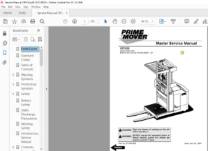
BT Prime-Mover CSX10/20/30/40 WSX22/30/40 WRX30 Master Service Manual – PDF
$35.95
BT Prime-Mover CSX10/20/30/40 WSX22/30/40 WRX30 Master Service Manual – PDF DOWNLOAD
Instant PDF Download
Available immediately
Save to Your Device
Download & keep forever
Antivirus Scanned
100% virus-free
Trusted Worldwide
175,000+ customers
Description
BT Prime-Mover CSX10/20/30/40 WSX22/30/40 WRX30 Master Service Manual – PDF DOWNLOAD
FILE DETAILS:
BT Prime-Mover CSX10/20/30/40 WSX22/30/40 WRX30 Master Service Manual – PDF DOWNLOAD
Language : English
Pages : 1067
Downloadable : Yes
File Type : PDF
304959-000 1996_October
304959-000 1997_October
304959-000 2002_April
IMAGES PREVIEW OF THE MANUAL:
TABLE OF CONTENTS:
BT Prime-Mover CSX10/20/30/40 WSX22/30/40 WRX30 Master Service Manual – PDF DOWNLOAD
Front Cover..................................................................................   2
Table of Contents............................................................................   4
Warning Symbols..............................................................................   6
	1. Warning Levels........................................................................   6
Prohibitory Symbols..........................................................................   7
	1.1 Ordinance Symbols....................................................................   7
Introduction, Service Manual.................................................................   8
Contents, Section M..........................................................................  10
	General Product Information..............................................................  12
		1. Presentation of the Walkie Trucks CSX20/30/40, WSX30/40, and WRX30................  12
			1.1 Intended Application of the Trucks...........................................  12
			1.2 Forbidden Application of the Truck...........................................  13
			1.3 Truck Data...................................................................  13
			1.4 CSX Dimensions...............................................................  14
			1.5 WSX Dimensions...............................................................  15
			1.6 WRX Dimensions...............................................................  16
			1.7 Data Plate...................................................................  17
		2. Main Components...................................................................  19
		Inch (SAE) and Metric Fasteners......................................................  22
		Introduction.........................................................................  23
			Nomenclature, Threads............................................................  23
			Strength Identification..........................................................  24
				Table #1 Bolts and Screws....................................................  25
				Table #2 Studs and Nuts......................................................  26
				Table #3 Torque Nuts.........................................................  27
				Table #4 Torque Nuts with Nylon Insert.......................................  28
			Table #5 Conversion Table for Metric and English Units...........................  29
			Table #6.........................................................................  31
	Technical Service Data...................................................................  32
	Ordering Spare Parts.....................................................................  36
Contents, Section P..........................................................................  38
	Introduction, Maintenance................................................................  40
		1. Safe Jacking Procedure............................................................  40
	Service Schedule.........................................................................  42
		1. Preventive Maintenance Schedule...................................................  42
		2. Planned Maintenance Procedures....................................................  46
			Services to be Performed Daily or at Each 8 Hour Operating Shift.................  46
				Battery......................................................................  46
				Hydraulic System.............................................................  46
				Frame/Sheet Metal............................................................  46
				Wheels/Tires.................................................................  47
				Functions/Operations.........................................................  47
			Services to be Performed Monthly or Every 250 Operating Hours....................  47
				Inspection...................................................................  47
				Transmission.................................................................  47
				Brakes.......................................................................  47
				Battery......................................................................  48
				Electrical Connections.......................................................  48
				Line Contactor Tips (NOT Sealed).............................................  48
				Motor Brushes................................................................  48
				Drive Motor..................................................................  49
				Hydraulic Reservoir..........................................................  49
				Frame Lube...................................................................  49
				Pivot Points.................................................................  49
			Services to be Performed Annually or Every 1000 Operating Hours..................  49
				Inspection...................................................................  50
				Transmission.................................................................  50
				Battery......................................................................  50
				Hydraulic System.............................................................  51
				Brakes.......................................................................  51
	Lubrication Chart........................................................................  52
	Oil and Grease Specifications............................................................  54
		1. Approved Oils and Grease..........................................................  54
Contents, Section S..........................................................................  56
	Chassis, CSX.............................................................................  58
		1. General...........................................................................  58
		2. Main Components...................................................................  59
	Chassis, WRX and WSX.....................................................................  60
		1. General...........................................................................  60
		2. Support Arms......................................................................  61
	Drive Motor..............................................................................  62
		1. General Information...............................................................  62
		2. Operating Conditions..............................................................  62
		3. Troubleshooting...................................................................  62
		Drive Motor 200 AMP..................................................................  70
			1. Component Repair..............................................................  71
			2. Inspection and Troubleshooting................................................  72
				2.1 Drive End Head...........................................................  72
				2.2 Commutator End Head......................................................  72
				2.3 Bearings.................................................................  72
				2.4 Brush and Commutator.....................................................  73
				2.5 Armature.................................................................  73
				2.6 Frame and Field Assembly.................................................  74
				2.7 Assembly.................................................................  76
			3. When Changing Brushes.........................................................  77
		Drive Motor 300 AMP..................................................................  78
			4. Component Repair..............................................................  79
			5. Inspection and Troubleshooting................................................  82
				5.1 Drive End Head...........................................................  82
				5.2 Commutator End Head......................................................  82
				5.3 Bearings.................................................................  82
				5.4 Brush and Commutator.....................................................  83
				5.5 Armature.................................................................  83
				5.6 Frame and Field Assembly.................................................  84
				5.7 Assembly.................................................................  86
			6. When Changing Brushes.........................................................  87
	Transmission.............................................................................  88
		1. System Description................................................................  88
		2. Troubleshooting...................................................................  89
		3. Axle Seal Removal and Installation................................................  90
			3.1 Removal......................................................................  90
			3.2 Installation.................................................................  90
		4. Transmission Removal/Installation.................................................  91
			4.1 Removal......................................................................  91
			4.2 Installation.................................................................  92
		5. Transmission Assembly.............................................................  94
			5.1 Disassembly..................................................................  95
			5.2 Assembly.....................................................................  95
	Parking Brake System.....................................................................  98
		1. Brake Theory of Operation......................................................... 100
		2. Brake Adjustment.................................................................. 101
		3. Brake Shoe Removal/Installation................................................... 102
	Wheels................................................................................... 104
		1. Stabilizing Caster................................................................ 104
			1.1 Maintenance and Adjustments.................................................. 105
			1.2 Caster Adjustment............................................................ 105
			1.3 Troubleshooting.............................................................. 106
			1.4 Stabilizing Caster........................................................... 106
		2. Drive Wheel....................................................................... 108
			2.1 Removal...................................................................... 108
			2.2 Installation................................................................. 109
	Load Wheels, CSX......................................................................... 110
	Load Wheels, WRX/WSX..................................................................... 112
	Steering................................................................................. 114
		1. Control Handle Head............................................................... 114
			1.1 Removal...................................................................... 114
			1.2 Installation................................................................. 115
		2. Control Handle Stem............................................................... 115
			2.1 Removal...................................................................... 115
			2.2 Installation................................................................. 115
	Electrical System........................................................................ 118
		1. Electrical Panel Components....................................................... 118
		2. List of Symbols................................................................... 119
			2.1 Circuit Diagram 1(5)......................................................... 121
			2.2 Circuit Diagram 2(5)......................................................... 122
			2.3 Circuit Diagram 3(5)......................................................... 123
			2.4 Circuit Diagram 4(5)......................................................... 124
			2.5 Circuit Diagram 5(5)......................................................... 125
		3. Description of Function........................................................... 126
			3.1 General...................................................................... 126
			3.2 Adjustable Settings.......................................................... 126
			3.3 References................................................................... 126
			3.4 Key Switch S17 in the ON Position............................................ 126
			3.5 The Operating Arm in Drive Position, S10, Brake Switch Closed................ 127
			3.6 Driving, Fork Direction...................................................... 127
			3.7 Driving, Steer Wheel Direction............................................... 127
			3.8 Reversing/Motor Brake Fork Direction to Steer Wheel Direction................ 127
			3.9 Reversing/Motor Brake Steer Wheel Direction to Fork Direction................ 127
			3.10 Reverser Switch............................................................. 128
			3.11 Lifting the Forks........................................................... 128
			3.12 Lowering the Forks.......................................................... 128
			3.13 Horn........................................................................ 128
		4. Options........................................................................... 129
			4.1 Lifting the Forks (Manual Valve)............................................. 129
			4.2 Tilting the Forks............................................................ 129
			4.3 Sideshifting the Forks....................................................... 129
			4.4 Extend/Retract the Forks..................................................... 129
	Contactor, 300 AMP....................................................................... 132
		1. Maintenance....................................................................... 132
			1.1 Removal/Replacement of Contact Tips.......................................... 133
	Contactor, "EE".......................................................................... 136
		2. Maintenance....................................................................... 137
			2.1 Removal/Replacement of Contact Tips.......................................... 137
	Battery Controller/Hourmeter............................................................. 140
		1. General........................................................................... 140
		2. Electrical........................................................................ 140
			2.1 Voltage...................................................................... 140
		3. Battery Controller (BC)........................................................... 141
			3.1 General...................................................................... 141
			3.2 Reset........................................................................ 143
			3.3 Key Switch................................................................... 143
			3.4 Hourmeter.................................................................... 143
		4. Troubleshooting................................................................... 144
			4.1 Battery Discharge Indicator (BDI)............................................ 144
			4.2 Hourmeter.................................................................... 146
	Transistor Controller.................................................................... 148
		1. Motor Circuit..................................................................... 148
		2. Control Circuit................................................................... 149
		3. Technical Specification........................................................... 151
		4. Adjustment of Controller.......................................................... 153
			4.1 Connection of Handset........................................................ 153
		5. Maintenance....................................................................... 154
			5.1 Safety....................................................................... 154
			5.2 Cleaning..................................................................... 154
		6. Diagnostics and Troubleshooting................................................... 155
			6.1 Handset Diagnostics.......................................................... 155
			6.2 Troubleshooting.............................................................. 155
			6.3 Troubleshooting Chart Using the Handset...................................... 158
	Electrical System Troubleshooting Chart Index............................................ 160
	Electrical System Troubleshooting Charts................................................. 162
	Handset Operation........................................................................ 180
		1. Operating Modes................................................................... 181
		2. Peace of Mind Programming......................................................... 185
		3. Handset Self Test................................................................. 186
	Pump Motor............................................................................... 188
		1. Component Repair.................................................................. 189
		2. Inspection and Troubleshooting.................................................... 191
			2.1 Drive End Head............................................................... 191
			2.2 Commutator End Head.......................................................... 191
			2.3 Bearings..................................................................... 191
			2.4 Brush and Commutator......................................................... 192
			2.5 Armature..................................................................... 192
			2.6 Frame and Field Assembly..................................................... 193
			2.7 Assembly..................................................................... 195
		3. When Changing Brushes............................................................. 196
	Hydraulic System......................................................................... 198
		1. General........................................................................... 198
		2. Description of Function........................................................... 198
			2.1 Hydraulic Schematic.......................................................... 198
			CSX Hydraulic Schematic.......................................................... 199
			WRX Hydraulic Schematic.......................................................... 200
			WSX Hydraulic Schematic.......................................................... 201
			2.2 Main Components.............................................................. 202
			2.3 Description.................................................................. 202
		3. Maintenance....................................................................... 203
			3.1 Maintenance and Adjustments.................................................. 203
			3.2 Troubleshooting.............................................................. 204
				Relief Valve................................................................. 206
				Figure 6110.................................................................. 207
				Solenoid Operated Valve...................................................... 208
				Pump and Motor............................................................... 208
				Reservoir and Pump........................................................... 209
	Manual Spool Valve....................................................................... 212
		Figure 0640.......................................................................... 212
		Figure 6160.......................................................................... 213
		Removal.............................................................................. 214
		Disassembly and Inspection........................................................... 215
		Assembly............................................................................. 216
	Mast, 2 Stage............................................................................ 218
		1. Shimming.......................................................................... 220
			1.1 Shimming the Carriage........................................................ 220
			1.2 Shimming the Rails........................................................... 221
		2. Two Stage Mast.................................................................... 223
			2.1 Removal...................................................................... 223
			2.2 Installation................................................................. 225
			2.3 Disassembly.................................................................. 226
			2.4 Assembly..................................................................... 227
	Mast, 3 Stage............................................................................ 230
		1. Shimming.......................................................................... 231
			1.1 Shimming the Carriage........................................................ 231
			1.2 Shimming the Rails........................................................... 232
		2. Three Stage Mast.................................................................. 235
			2.1 Removal...................................................................... 235
			2.2 Installation................................................................. 236
			2.3 Disassembly.................................................................. 237
			2.4 Assembly..................................................................... 238
	Reach.................................................................................... 242
		1. Maintenance....................................................................... 242
		2. Reach Repair...................................................................... 243
			2.1 Disassembly.................................................................. 243
			2.2 Assembly..................................................................... 244
	Lift Cylinder, 2 Stage................................................................... 248
		1. Two Stage Full Freelift Mast Freelift Cylinder Repair............................. 249
			1.2 Disassembly.................................................................. 249
			1.3 Assembly..................................................................... 249
			1.4 Installation................................................................. 250
		2. Two Stage Full Freelift Mast Staging Cylinder Repair.............................. 251
			2.1 Removal...................................................................... 251
			2.2 Disassembly.................................................................. 251
			2.3 Assembly..................................................................... 251
			2.4 Installation................................................................. 252
		3. Two Stage Mast Lift Cylinder Repair............................................... 253
			3.1 Removal...................................................................... 253
			3.2 Disassembly.................................................................. 253
			3.3 Assembly..................................................................... 253
			3.4 Installation................................................................. 254
	Lift Cylinder, 3 Stage................................................................... 256
		1. Freelift Cylinder Repair.......................................................... 257
			1.1 Removal...................................................................... 257
			1.2 Disassembly.................................................................. 257
			1.3 Assembly..................................................................... 257
			1.4 Installation................................................................. 258
		2. Staging Cylinder Repair........................................................... 259
			2.1 Removal...................................................................... 259
			2.2 Disassembly.................................................................. 259
			2.3 Assembly..................................................................... 259
			2.4 Installation................................................................. 260
	Tilt Cylinder, CSX....................................................................... 262
		1. Removal........................................................................... 263
		2. Disassembly....................................................................... 263
		3. Inspection........................................................................ 264
		4. Assembly.......................................................................... 265
		5. Installation...................................................................... 265
	Tilt Cylinder, WRX....................................................................... 268
		1. Removal........................................................................... 269
		2. Disassembly....................................................................... 269
		3. Inspection........................................................................ 270
		4. Assembly.......................................................................... 270
		5. Installation...................................................................... 271
	Reach Cylinder, WRX...................................................................... 274
		1. Removal........................................................................... 275
		2. Disassembly....................................................................... 275
		3. Inspection........................................................................ 276
		4. Assembly.......................................................................... 276
		5. Installation...................................................................... 277
Back Cover................................................................................... 279
Front Cover.................................................................................. 280
BT Standard Codes............................................................................ 282
Table of Contents............................................................................ 284
Warning Symbols.............................................................................. 288
	H 1. Warning Levels...................................................................... 288
Prohibitory Symbols.......................................................................... 289
	1. Ordinance Symbols..................................................................... 289
Introduction, Service Manual................................................................. 290
Contents, Section M.......................................................................... 292
	1. Machine Information................................................................... 292
General Product Information.................................................................. 294
	1. Presentation of the Walkie Trucks..................................................... 294
		H Heading3 First - 1.1. Intended Application of the Trucks........................... 294
		H Heading3 - 1.2. Forbidden Application of the Truck................................. 295
		H Heading3 - 1.3. Truck Data......................................................... 295
		H Heading3 - 1.4. CSX Dimensions..................................................... 296
		H Heading3 - 1.5. WSX Dimensions..................................................... 297
		H Heading3 - 1.6. WRX Dimensions..................................................... 298
		H Heading3 - 1.7. Data Plate......................................................... 299
	2. Main Components....................................................................... 300
Inch (SAE) and Metric Fasteners.............................................................. 304
	1. Introduction.......................................................................... 304
	2. Nomenclature, Threads................................................................. 305
	3. Strength Identification............................................................... 306
	4. Conversion of Metric and English Units................................................ 312
Technical Service Data....................................................................... 314
Ordering Spare Parts......................................................................... 318
Contents, Section P.......................................................................... 320
	1. Planned Maintenance................................................................... 320
Introduction, Maintenance.................................................................... 322
	1. Safe Jacking Procedure................................................................ 322
Service Schedule............................................................................. 324
	1. Planned Maintenance Schedule.......................................................... 324
	2. Planned Maintenance Procedures........................................................ 330
		H Heading3 First - 2.1. Services to be performed daily............................... 330
			H Heading4 First - 2.1.1. Battery Discharge Indicator with slow down............. 330
			H Heading4 - 2.1.2. Hydraulic System............................................. 330
			H Heading4 - 2.1.3. Frame/Sheet Metal............................................ 331
			H Heading4 - 2.1.4. Wheels/Tires................................................. 331
			H Heading4 - 2.1.5. Functions/Operations......................................... 331
		2.2. Services to be performed monthly................................................ 332
			2.2.1. Inspection................................................................ 332
			2.2.2. Transmission.............................................................. 332
			2.2.3. Brakes.................................................................... 332
			2.2.4. Battery................................................................... 332
			2.2.5. Electrical Connections.................................................... 332
			2.2.6. Contactor Tips (NOT Sealed)............................................... 333
			2.2.7. Motor Brushes............................................................. 333
			2.2.8. Drive Motor............................................................... 333
			2.2.9. Hydraulic Reservoir....................................................... 333
			2.2.10. Frame Lube (“Lubrication Chart” on page 57).............................. 333
			2.2.11. Pivot Points............................................................. 334
		2.3. Services to be performed annually............................................... 335
			2.3.1. Inspection................................................................ 335
			2.3.2. Transmission.............................................................. 335
			2.3.3. Battery................................................................... 335
			2.3.4. Hydraulic System.......................................................... 335
			2.3.5. Brakes.................................................................... 336
Lubrication Chart............................................................................ 338
Oil and Grease Specifications................................................................ 340
	1. Approved Oils and Grease.............................................................. 340
Contents, Section S.......................................................................... 342
	1. Service Instructions.................................................................. 342
Chassis, CSX................................................................................. 344
	1. General............................................................................... 344
	2. Main Components....................................................................... 345
Chassis, WRX and WSX......................................................................... 346
	1. General............................................................................... 346
	2. Support Arms.......................................................................... 347
Drive Motor.................................................................................. 348
	1. General Information................................................................... 348
	2. Operating Conditions.................................................................. 348
	3. Troubleshooting....................................................................... 348
Drive Motor 200 AMP.......................................................................... 354
	1. Component Repair...................................................................... 355
		1.1. Disassembly..................................................................... 355
	2. Inspection and Troubleshooting........................................................ 357
		2.1. Drive End Head.................................................................. 357
		2.2. Commutator End Head............................................................. 357
		2.3. Bearings........................................................................ 357
		2.4. Brush and Commutator............................................................ 358
		2.5. Armature........................................................................ 358
		2.6. Frame and Field Assembly........................................................ 359
			2.6.1. Testing................................................................... 359
			2.6.2. Frame and Field Service Notes............................................. 360
		2.7. Assembly........................................................................ 361
			2.7.1. Field Coil Installation................................................... 361
			2.7.2. Bearing Installation...................................................... 361
			2.7.3. After Assembly............................................................ 362
	3. When Changing Brushes................................................................. 362
Drive Motor 300 AMP.......................................................................... 364
	1. Component Repair...................................................................... 365
	2. Inspection and Troubleshooting........................................................ 368
		2.1. Drive End Head.................................................................. 368
		2.2. Commutator End Head............................................................. 368
		2.3. Bearings........................................................................ 368
		2.4. Brush and Commutator............................................................ 369
		2.5. Armature........................................................................ 369
		2.6. Frame and Field Assembly........................................................ 370
			2.6.1. Testing................................................................... 370
			2.6.2. Frame and Field Service Notes............................................. 371
		2.7. Assembly........................................................................ 372
			2.7.1. Field Coil Installation................................................... 372
			2.7.2. Bearing Installation...................................................... 372
			2.7.3. After Assembly............................................................ 373
	3. When changing brushes................................................................. 373
Transmission................................................................................. 374
	1. System description.................................................................... 374
	2. Troubleshooting....................................................................... 374
	3. Removal............................................................................... 376
	4. Installation.......................................................................... 378
Transmission Axle Seal....................................................................... 380
	1. General Information................................................................... 380
		1.1. Removal......................................................................... 380
		1.2. Installation.................................................................... 380
Transmission Disassembly / Assembly.......................................................... 382
	1. Disassembly........................................................................... 383
	2. Assembly.............................................................................. 383
Parking Brake System......................................................................... 386
	1. Brake Theory of Operation............................................................. 388
	2. Brake Adjustment...................................................................... 389
	3. Brake Shoe Removal / Installation..................................................... 390
Drive Wheel.................................................................................. 392
	3.1. Removal............................................................................. 392
	3.2. Installation........................................................................ 393
Load Wheels, CSX............................................................................. 394
	1. Removeal and Installation............................................................. 394
Load Wheels, WRX/WSX......................................................................... 396
	1. Removal and Installation.............................................................. 396
Wheels....................................................................................... 398
	1. Stabilizing Caster.................................................................... 398
		1.1. Maintenance and Adjustments..................................................... 399
		1.2. Caster Adjustment............................................................... 399
		1.3. Troubleshooting................................................................. 400
		1.4. Stabilizing Caster.............................................................. 400
			1.4.1. Caster Replacement........................................................ 400
Stabilizing Caster........................................................................... 402
	1. Stabilizing Caster.................................................................... 402
		1.1. Disassembly..................................................................... 403
		1.2. Inspection...................................................................... 404
		1.3. Assembly........................................................................ 405
Steering Arm / Handle........................................................................ 406
	1. Control Handle Stem................................................................... 407
		1.1. Removal......................................................................... 407
		1.2. Inspection...................................................................... 407
		1.3. Installation.................................................................... 408
Steering Handle Head......................................................................... 410
	1. Control Handle Head................................................................... 412
		1.1. Removal......................................................................... 412
		1.2. Installation.................................................................... 412
	2. Direction Control Switches............................................................ 413
	3. Horn, Raise, and Lower Switches....................................................... 414
	4. Potentiometer......................................................................... 416
Electrical System............................................................................ 418
	1. Electrical Panel Components........................................................... 418
	2. List of Symbols....................................................................... 419
		2.1. Circuit Diagram 1(5)............................................................ 421
		2.2. Circuit Diagram 2(5)............................................................ 422
		2.3. Circuit Diagram 3(5)............................................................ 423
		2.4. Circuit Diagram 4(5)............................................................ 424
		2.5. Circuit Diagram 5(5)............................................................ 425
	3. Description of Function............................................................... 426
		3.1. General......................................................................... 426
		3.2. Adjustable Settings:............................................................ 426
		3.3. References:..................................................................... 426
		3.4. Key Switch S17 in the ON Position............................................... 426
		3.5. The Operating Arm in Drive Position, S10, Brake Switch Closed................... 427
		3.6. Driving, Fork Direction......................................................... 427
		3.7. Driving, Steer Wheel Direction.................................................. 427
		3.8. Reversing/Motor Brake Fork Direction to Steer Wheel Direction................... 427
		3.9. Reversing/Motor Brake Steer Wheel Direction to Fork Direction................... 427
		3.10. Reverser switch................................................................ 428
		3.11. Lifting the Forks.............................................................. 428
		3.12. Lowering the Forks............................................................. 428
		3.13. Horn........................................................................... 428
	4. Options............................................................................... 429
		4.1. Lifting the Forks (Manual Valve)................................................ 429
		4.2. Tilting the Forks............................................................... 429
		4.3. Sideshifting the Forks.......................................................... 429
		4.4. Extend/Retract the Forks........................................................ 429
300/400 Amp Contactor........................................................................ 432
	1. Maintenance........................................................................... 433
		1.1. Removal/Replacement of Contact Tips............................................. 433
“EE” Contactor............................................................................... 436
	1. Maintenance........................................................................... 437
		1.1. Removal/Replacement of Contact Tips............................................. 437
Battery Controller / Hourmeter / Lift Interrupt.............................................. 440
	1. General Information................................................................... 440
	2. Electrical............................................................................ 440
		2.1. Voltage......................................................................... 440
			2.1.1. The Contact Voltage and Current Ratings for Switching Resistive Loads..... 441
			2.1.2. Memory Retention.......................................................... 441
	3. Battery Controller (BC)............................................................... 441
		3.1. General Information............................................................. 441
			3.1.1. Discharge Adjustment...................................................... 441
		3.2. Reset........................................................................... 443
		3.3. Key Switch...................................................................... 443
		3.4. Hourmeter....................................................................... 444
	4. Troubleshooting....................................................................... 444
		4.1. Battery Discharge Indicator (BDI)............................................... 444
			4.1.1. No Reset.................................................................. 444
			4.1.2. Reset After Break in Power................................................ 444
			4.1.3. No Discharge, Gauge Does Not Run Down..................................... 445
			4.1.4. No Lockout................................................................ 445
			4.1.5. No Lift................................................................... 445
			4.1.6. Early Lockout............................................................. 446
			4.1.7. LEDs Do Not Light......................................................... 446
		4.2. Hourmeter....................................................................... 446
			4.2.1. No Display................................................................ 446
			4.2.2. Hourmeter Glass Icon Does Not Flash....................................... 446
			4.2.3. Hourmeter Glass Icon Always Flashes....................................... 447
Transistor Controller........................................................................ 448
	1. Motor Circuit......................................................................... 448
	2. Control Circuit....................................................................... 449
	3. Technical Specification............................................................... 451
	4. Adjustment of Controller.............................................................. 453
		4.1. Connection of Handset........................................................... 453
	5. Maintenance........................................................................... 454
		5.1. Safety.......................................................................... 454
		5.2. Cleaning........................................................................ 454
	6. Diagnostics and Troubleshooting....................................................... 455
		6.1. Handset Diagnostics............................................................. 455
		6.2. Troubleshooting................................................................. 455
			6.2.1. Procedure Troubleshooting Instructions.................................... 457
		6.3. Troubleshooting Chart Using the Handset......................................... 458
Electrical System Troubleshooting Chart Index................................................ 460
Electrical System Troubleshooting Charts..................................................... 462
Handset Operation............................................................................ 480
	1. Operating Modes:...................................................................... 481
	2. Revert to Previous Settings........................................................... 485
	3. Handset Self Test..................................................................... 486
	4. LED Diagnostics....................................................................... 487
Pump Motor................................................................................... 488
	1. Component Repair...................................................................... 489
		1.1. Disassembly..................................................................... 489
	2. Inspection and Troubleshooting........................................................ 491
		2.1. Drive End Head.................................................................. 491
		2.2. Commutator End Head............................................................. 491
		2.3. Bearings........................................................................ 491
		2.4. Brush and Commutator............................................................ 492
		2.5. Armature........................................................................ 492
		2.6. Frame and Field Assembly........................................................ 493
			2.6.1. Testing................................................................... 493
			2.6.2. Frame and Field Service Notes............................................. 494
		2.7. Assembly........................................................................ 495
			2.7.1. Field Coil Installation................................................... 495
			2.7.2. Bearing Installation...................................................... 495
			2.7.3. After Assembly............................................................ 496
	3. When changing brushes................................................................. 496
Hydraulic System............................................................................. 498
	1. General............................................................................... 498
	2. Description of Function............................................................... 498
		2.1. Hydraulic Schematic............................................................. 498
		2.2. CSX Hydraulic Schematic......................................................... 499
		2.3. WRX Hydraulic Schematic......................................................... 500
		2.4. WSX Hydraulic Schematic......................................................... 501
	3. Main Components....................................................................... 502
		3.1. Description..................................................................... 502
			3.1.1. Lift (Solenoid valve)..................................................... 502
			3.1.2. Lift (Mechanical Valve)................................................... 502
			3.1.3. Lower (Solenoid Valve).................................................... 502
			3.1.4. Lower (Mechanical Valve).................................................. 503
			3.1.5. Relief Pressure........................................................... 503
			3.1.6. Compensating Cylinder..................................................... 503
	4. Maintenance........................................................................... 503
	5. Adjustments........................................................................... 503
	6. Troubleshooting....................................................................... 504
		6.1. Primary Malfunctions............................................................ 504
			6.1.1. Failure to raise the load................................................. 505
			6.1.2. Failure to raise the load................................................. 505
			6.1.3. Failure to raise the load................................................. 505
	7. Removal............................................................................... 506
	8. Installation.......................................................................... 508
Lift Pump Assembly........................................................................... 510
	1. Disassembly........................................................................... 512
	2. Inspection............................................................................ 513
	3. Assembly.............................................................................. 514
Manual Spool Valve........................................................................... 516
	1. Removal............................................................................... 518
	2. Disassembly and Inspection............................................................ 519
	3. Assembly.............................................................................. 520
Mast, 2 Stage................................................................................ 522
	1. Shimming Mast on Truck................................................................ 524
		1.1. Shimming the Carriage........................................................... 524
		1.2. Shimming the Rails.............................................................. 525
	2. Two Stage Mast........................................................................ 527
		2.1. Removal......................................................................... 527
		2.2. Installation.................................................................... 529
		2.3. Disassembly..................................................................... 530
		2.4. Assembly........................................................................ 531
Mast, 3 Stage................................................................................ 534
	1. Shimming Mast on Truck................................................................ 535
		1.1. Shimming the Carriage........................................................... 535
		1.2. Shimming the Rails.............................................................. 536
	2. Three Stage Mast...................................................................... 540
		2.1. Removal......................................................................... 540
		2.2. Installation.................................................................... 541
		2.3. Disassembly..................................................................... 542
		2.4. Assembly........................................................................ 544
Sideshifter.................................................................................. 548
	1. Mounting Instructions................................................................. 550
		1.1. Installation.................................................................... 550
	2. Operation and Maintenance............................................................. 551
		2.1. Lower Slides.................................................................... 552
		2.2. Upper Slides.................................................................... 552
		2.3. Cylinder........................................................................ 552
Reach, Single................................................................................ 554
	1. Maintenance........................................................................... 554
	2. Reach Repair.......................................................................... 556
		2.1. Disassembly..................................................................... 556
			2.1.1. Front Frame Removal....................................................... 556
			2.1.2. Outer Arm Removal......................................................... 556
			2.1.3. Inner Arm Removal......................................................... 556
			2.1.4. Rear Frame Removal........................................................ 557
			2.1.5. Reach Cylinder Removal.................................................... 557
		2.2. Assembly........................................................................ 558
			2.2.1. Reach Cylinder Installation............................................... 558
			2.2.2. Rear Frame Installation................................................... 558
			2.2.3. Inner Arm Installation.................................................... 558
			2.2.4. Outer Arm Installation.................................................... 559
Lift Cylinder, 2 Stage....................................................................... 560
	1. Two Stage Full Freelift Mast Freelift Cylinder Repair................................. 561
		1.1. Removal......................................................................... 561
		1.2. Disassembly..................................................................... 562
		1.3. Assembly........................................................................ 562
		1.4. Installation.................................................................... 562
	2. Two Stage Full Freelift Mast Staging Cylinder Repair.................................. 563
		2.1. Removal......................................................................... 563
		2.2. Disassembly..................................................................... 563
		2.3. Assembly........................................................................ 564
		2.4. Installation.................................................................... 564
	3. Two Stage Mast Lift Cylinder Repair................................................... 565
		3.1. Removal......................................................................... 565
		3.2. Disassembly..................................................................... 565
		3.3. Assembly........................................................................ 566
		3.4. Installation.................................................................... 566
Freelift Cylinder, 3 Stage................................................................... 568
	1. Freelift Cylinder Repair.............................................................. 569
		1.1. Removal......................................................................... 569
		1.2. Disassembly..................................................................... 570
		1.3. Assembly........................................................................ 570
		1.4. Installation.................................................................... 570
Tilt Cylinder, CSX........................................................................... 572
	1. Removal............................................................................... 573
	2. Disassembly........................................................................... 574
	3. Inspection............................................................................ 575
	4. Assembly.............................................................................. 576
	5. Installation.......................................................................... 577
Tilt Cylinder, WRX........................................................................... 578
	1. Removal............................................................................... 579
	2. Disassembly........................................................................... 580
	3. Inspection............................................................................ 581
	4. Assembly.............................................................................. 582
	5. Installation.......................................................................... 583
Reach Cylinder............................................................................... 584
	1. Removal............................................................................... 585
	2. Disassembly........................................................................... 586
	3. Inspection............................................................................ 587
	4. Assembly.............................................................................. 588
	5. Installation.......................................................................... 589
Back Cover................................................................................... 591
Front Cover.................................................................................. 592
Standard Codes............................................................................... 594
Index........................................................................................ 596
Warning Symbols.............................................................................. 606
	1. Warning Levels........................................................................ 606
Prohibitory Symbols.......................................................................... 607
	1. Ordinance Symbols..................................................................... 607
Safety....................................................................................... 608
	1. General Safety........................................................................ 608
Battery Safety............................................................................... 612
Static Safety................................................................................ 617
Welding Safety............................................................................... 618
Introduction, Service Manual................................................................. 620
Contents, Section M.......................................................................... 622
	1. Machine Information................................................................... 622
General Product Information.................................................................. 624
	1. Presentation of Walkie Trucks......................................................... 624
		1.1. Truck Side Views................................................................ 625
		1.1. Intended Truck Application...................................................... 625
		1.2. Prohibited Truck Application.................................................... 625
		1.3. Truck Data...................................................................... 626
		1.4. CSX10 Dimensions................................................................ 627
		1.5. CSX20 Dimensions................................................................ 628
		1.6. CSX30 Dimensions................................................................ 629
		1.7. CSX40 Dimensions................................................................ 630
		1.8. WSX22 Dimensions................................................................ 631
		1.9. WSX30 Dimensions................................................................ 632
		1.10. WSX40 Dimensions............................................................... 633
		1.11. WRX30 Dimensions............................................................... 634
		1.12. Data Plate..................................................................... 635
	2. Main Components....................................................................... 637
Inch (SAE) and Metric Fasteners.............................................................. 640
	1. Introduction.......................................................................... 640
	2. Nomenclature, Threads................................................................. 641
	3. Strength Identification............................................................... 642
	4. Conversion of Metric and English Units................................................ 649
Technical Service Data....................................................................... 652
Ordering Spare Parts......................................................................... 656
Contents, Section P.......................................................................... 658
	1. Planned Maintenance................................................................... 658
Introduction, Maintenance.................................................................... 660
	1. Jacking Truck Off The Floor........................................................... 661
		1.1. Elevate Rear of Truck........................................................... 661
		1.1. Elevate Either Side of Truck.................................................... 661
	2. Lubricants............................................................................ 662
		2.1. Standard........................................................................ 662
		2.2. Corrosion....................................................................... 662
		2.3. Cold Storage.................................................................... 663
Service Schedule............................................................................. 666
	1. Planned Maintenance Schedule.......................................................... 666
	2. Planned Maintenance Procedures........................................................ 671
		2.1. Services Performed Daily or Every 8 Operating Hours............................. 671
			2.1.1. Battery Discharge Indicator with slow down................................ 671
			2.1.2. Hydraulic System.......................................................... 671
			2.1.3. Frame/Sheet Metal......................................................... 672
			2.1.4. Wheels/Tires.............................................................. 672
			2.1.5. Functions/Operations...................................................... 672
		2.2. Services Performed Monthly or Every 120 Operating Hours......................... 672
			2.2.1. Inspection................................................................ 672
			2.2.2. Transmission.............................................................. 672
			2.2.3. Brakes.................................................................... 673
			2.2.4. Battery................................................................... 673
			2.2.5. Electrical Connections.................................................... 673
			2.2.6. Contactor Tips (NOT Sealed)............................................... 673
			2.2.7. Motor Brushes............................................................. 673
			2.2.8. Drive Motor............................................................... 674
			2.2.9. Hydraulic Reservoir....................................................... 674
			2.2.10. Frame Lube............................................................... 674
			2.2.11. Pivot Points............................................................. 674
		2.3. Services Performed Every 480 or 960 Operating Hours............................. 675
			2.3.1. Drive Motor............................................................... 675
		2.4. Services Performed Annually or Every 1400 Operating Hours....................... 676
			2.4.1. Inspection................................................................ 676
			2.4.2. Transmission.............................................................. 676
			2.4.3. Battery................................................................... 676
			2.4.4. Hydraulic System.......................................................... 677
			2.4.5. Brakes.................................................................... 677
			2.4.6. Lift and Carriage Chains.................................................. 677
Lubrication Chart............................................................................ 678
Oil and Grease Specifications................................................................ 679
	1. Approved Oils and Grease.............................................................. 679
	2. CSX Grease & Mast Adjustment Points Location.......................................... 680
	3. WSX Grease & Mast Adjustment Points Location.......................................... 681
	4. WRX Grease & Mast Adjustment Points Location.......................................... 682
Contents, Section S.......................................................................... 684
	1. Service Instructions.................................................................. 684
Frame/Chassis................................................................................ 686
	1. General............................................................................... 688
	2. Main Components....................................................................... 688
Inspection Covers............................................................................ 690
Battery Roller (Optional).................................................................... 698
	1. Battery Cover, Optional (WSX22 “EE” Trucks Only)...................................... 700
		1.1. Inspection...................................................................... 700
		1.2. Removal......................................................................... 700
		1.3. Installation.................................................................... 701
	2. Battery Rollers....................................................................... 701
		2.1. Inspection...................................................................... 701
		2.2. Replacement..................................................................... 701
Driver Controls, One Spool................................................................... 702
	1. Removal............................................................................... 704
	2. Installation.......................................................................... 705
Driver Controls, Two Spool................................................................... 706
	1. Removal............................................................................... 709
	2. Installation.......................................................................... 710
Decals....................................................................................... 712
	1. Decal with Protective Sheet........................................................... 712
	2. Decal without Protective Sheet........................................................ 712
Motor Maintenance Schedule/Troubleshooting................................................... 716
	1. General Information................................................................... 716
	2. Operating Conditions.................................................................. 716
	3. Troubleshooting....................................................................... 717
Motor Repair................................................................................. 724
	1. Pump Motor............................................................................ 724
		1.1. Pump Motor Removal.............................................................. 725
		1.2. Pump Motor Installation......................................................... 725
	2. Drive Motor........................................................................... 726
		2.1. Brush Replacement............................................................... 732
		2.2. Drive Motor Removal............................................................. 732
		2.3. Drive Motor Installation........................................................ 733
	3. Component Repair...................................................................... 735
		3.1. Disassembly..................................................................... 735
	4. Inspection............................................................................ 737
		4.1. Drive End head.................................................................. 737
		4.2. Commutator End Head............................................................. 737
		4.3. Bearings........................................................................ 737
		4.4. Brush and Commutator............................................................ 738
		4.5. Armature........................................................................ 740
		4.6. Frame and Field Assembly........................................................ 741
			4.6.1. Testing................................................................... 741
		4.7. Assembly/Testing................................................................ 742
			4.7.1. Bearing Installation...................................................... 742
			4.7.2. Testing................................................................... 743
Transmission................................................................................. 744
	1. System Description.................................................................... 744
	2. Troubleshooting....................................................................... 744
		2.1. Kick Panel...................................................................... 745
	3. Transmission Repair................................................................... 746
		3.1. Removal......................................................................... 747
		3.2. Installation.................................................................... 748
	4. Transmission Assembly................................................................. 750
		4.1. Disassembly..................................................................... 751
		4.2. Assembly........................................................................ 751
	5. Axle Seal............................................................................. 753
		5.1. Removal......................................................................... 753
		5.2. Installation.................................................................... 753
Parking Brake System......................................................................... 756
	1. Brake Theory of Operation............................................................. 758
	2. Brake Adjustment...................................................................... 759
	3. Brake Shoe Removal / Installation..................................................... 760
Drive Wheel.................................................................................. 762
	1. Removal............................................................................... 762
	2. Installation.......................................................................... 763
	3. Tire Pressing Procedure............................................................... 764
Support/Swivel Wheel......................................................................... 766
	1. Maintenance and Adjustments........................................................... 769
		1.1. Caster Adjustment............................................................... 770
	2. Troubleshooting....................................................................... 771
		2.1. Stabilizing Caster.............................................................. 771
			2.1.1. Caster Replacement........................................................ 771
Load Wheels.................................................................................. 772
	1. Removal and Installation.............................................................. 775
Caster Assembly.............................................................................. 776
	1. Disassembly........................................................................... 777
	2. Inspection............................................................................ 778
	3. Assembly.............................................................................. 779
Steering Arm/Wheel, Tiler Arm (Serial # 25268000 - 27323000)................................. 780
	1. Removal............................................................................... 781
	2. Inspection............................................................................ 782
	3. Installation.......................................................................... 783
Steering Arm/Wheel, Tiler Arm (Serial # 27323001 - UP)....................................... 784
	1. Removal............................................................................... 785
	2. Inspection............................................................................ 786
	3. Installation.......................................................................... 787
Steering Arm/Wheel, Head..................................................................... 788
	1. Control Handle Head................................................................... 789
		1.1. Removal......................................................................... 789
		1.2. Installation.................................................................... 789
	2. Direction Control Switches............................................................ 790
	3. Raise, Lower, and Horn Switches....................................................... 792
	4. Potentiometer......................................................................... 795
		4.1. Removal......................................................................... 795
		4.2. Installation.................................................................... 796
	5. Reverser Assembly Replacement......................................................... 800
Electrical Functions......................................................................... 802
	1. General............................................................................... 802
		1.1. Adjustable Settings............................................................. 802
		1.2. References...................................................................... 802
		1.3. Key Switch S17 in ON Position................................................... 803
		1.4. Operating Arm in Drive Position, S10, Brake Switch Closed....................... 803
		1.5. Travel Request, Forks First..................................................... 803
		1.6. Travel Request, Forks Trailing.................................................. 803
		1.7. Reversing/Motor Brake Forks First to Forks Trailing Direction................... 804
		1.8. Reversing/Motor Brake Forks Trailing to Forks First Direction................... 804
		1.9. Reverser switch................................................................. 804
		1.10. Lifting Forks.................................................................. 804
		1.11. Lowering Forks................................................................. 805
		1.12. Horn........................................................................... 805
	2. Options............................................................................... 805
		2.1. Lifting Forks (Manual Valve).................................................... 805
		2.2. Tilting Forks................................................................... 805
		2.3. Side Shifting Forks............................................................. 805
		2.4. Extend/Retract Forks............................................................ 806
Electrical Symbols........................................................................... 808
Electrical Schematics........................................................................ 814
Battery...................................................................................... 820
	1. Removal............................................................................... 820
	2. Installation.......................................................................... 821
	3. Battery Maintenance................................................................... 822
		3.1. Battery Inspection and Care..................................................... 822
		3.2. Battery Exterior Cleaning....................................................... 823
		3.3. Charging........................................................................ 823
	4. Storage............................................................................... 824
	5. Battery History Record................................................................ 824
Battery Connector............................................................................ 826
	1. Location.............................................................................. 826
	2. Inspection............................................................................ 827
	3. Installation.......................................................................... 827
200 Amp System Line Contactor................................................................ 830
	1. Replacement........................................................................... 830
		1.1. Removal......................................................................... 830
		1.2. Installation.................................................................... 830
300 Amp System Line Contactor (CSX30/40 only)................................................ 832
	1. Maintenance........................................................................... 832
		1.1. Removal/Replacement of Contact Tips............................................. 833
200/300 Amp System “EE” Line Contactor....................................................... 834
	1. Maintenance........................................................................... 834
		1.1. Removal/Replacement of Contact Tips............................................. 835
Battery Controller/Hourmeter/Lift Interrupt.................................................. 838
	1. General Information................................................................... 838
	2. Electrical............................................................................ 839
		2.1. Voltage......................................................................... 839
	3. Battery Controller (BC)............................................................... 840
		3.1. General Information............................................................. 840
			3.1.1. Discharge Adjustment...................................................... 840
		3.2. Reset........................................................................... 842
		3.3. Key Switch...................................................................... 842
		3.4. Hourmeter....................................................................... 843
	4. Troubleshooting....................................................................... 843
		4.1. Battery Discharge Indicator (BDI)............................................... 843
			4.1.1. No Reset.................................................................. 843
			4.1.2. Reset After Break in Power................................................ 844
			4.1.3. No Discharge, Gauge Does Not Run Down..................................... 844
			4.1.4. No Lockout................................................................ 844
			4.1.5. No Lift................................................................... 845
			4.1.6. Early Lockout............................................................. 845
			4.1.7. LEDs Do Not Light......................................................... 845
		4.2. Hourmeter....................................................................... 846
			4.2.1. No Display................................................................ 846
			4.2.2. Hourmeter Glass Icon Does Not Flash....................................... 846
			4.2.3. Hourmeter Glass Icon Always Flashes....................................... 846
Start/Stop Switches.......................................................................... 848
	1. General............................................................................... 848
		1.1. Test/Inspection................................................................. 848
	2. Master Control On/Off Switch (S21).................................................... 850
		2.1. Inspection...................................................................... 850
		2.2. Removal......................................................................... 850
		2.3. Installation.................................................................... 850
Light Assemblies............................................................................. 852
	1. Warning Lights (Option)............................................................... 852
		1.1. Removal......................................................................... 854
		1.2. Installation.................................................................... 854
	2. Travel/Back-up Alarm (Option)......................................................... 855
		2.1. Removal......................................................................... 855
		2.2. Installation.................................................................... 855
Transistor Controller........................................................................ 856
	1. Basics Of Circuit Operation........................................................... 856
		1.1. Control Features................................................................ 858
	2. Maintenance........................................................................... 859
		2.1. Safety.......................................................................... 859
		2.2. Cleaning........................................................................ 859
	3. Motor Circuit......................................................................... 860
	4. Control Circuit....................................................................... 861
	5. Troubleshooting Guidelines............................................................ 862
		5.1. General......................................................................... 864
	6. Shorts to Frame Test.................................................................. 865
	7. Definitions........................................................................... 869
	8. Diagnostics and Troubleshooting....................................................... 870
		8.1. Handset Diagnostics............................................................. 870
		8.2. Troubleshooting................................................................. 870
		8.3. Troubleshooting Chart........................................................... 872
		8.4. Technical Specification......................................................... 877
		8.5. Troubleshooting Chart Using Handset............................................. 878
Transistor Controller Troubleshooting........................................................ 880
	1. Troubleshooting Chart Index........................................................... 880
	2. Troubleshooting Charts................................................................ 881
Hydraulic System............................................................................. 900
	1. General............................................................................... 900
	2. Description of Function............................................................... 900
	3. Main Components....................................................................... 901
		3.1. Lift (Solenoid valve)........................................................... 901
		3.2. Lift (Mechanical Valve)......................................................... 901
		3.3. Lower (Solenoid Valve).......................................................... 901
		3.4. Lower (Mechanical Valve)........................................................ 901
		3.5. Relief Pressure................................................................. 901
		3.6. Compensating Cylinder........................................................... 902
		3.7. Reach (Solenoid valve).......................................................... 902
		3.8. Tilt (Solenoid valve)........................................................... 902
		3.9. Sideshift (Solenoid valve)...................................................... 902
	4. Maintenance........................................................................... 903
	5. Adjustments........................................................................... 904
	6. Troubleshooting....................................................................... 905
		6.1. Primary Malfunctions............................................................ 906
			6.1.1. Failure to raise load..................................................... 906
			6.1.2. Failure to raise load..................................................... 906
			6.1.3. Failure to raise load..................................................... 907
	7. Definitions........................................................................... 907
	8. Removal............................................................................... 908
	9. Installation.......................................................................... 910
Hydraulic Schematics......................................................................... 912
Hydraulic Fluid.............................................................................. 918
	1. Hydraulic Fluid Selection............................................................. 918
	2. Changing Hydraulic System Fluid....................................................... 918
	3. System Draining....................................................................... 919
	4. Refilling System...................................................................... 920
	5. Bleeding Hydraulic System............................................................. 921
Hydraulic Tank............................................................................... 922
	1. Removal............................................................................... 923
	2. Installation.......................................................................... 923
Hydraulic Pump Assembly...................................................................... 924
	1. Disassembly........................................................................... 926
	2. Inspection............................................................................ 927
	3. Assembly.............................................................................. 928
One Spool Control Valve...................................................................... 930
	1. Operators Controls Removal............................................................ 931
	2. Control Valve Disassembly and Inspection.............................................. 931
	3. Operators Controls Installation....................................................... 932
Two Spool Control Valve...................................................................... 933
	1. Operators Controls Removal............................................................ 934
	2. Control Valve Disassembly and Inspection.............................................. 934
	3. Operators Controls Installation....................................................... 935
Lift Cylinder, Two Stage Mast................................................................ 936
	1. Lift Cylinder, Two Stage Mast......................................................... 946
		1.1. Removal......................................................................... 946
		1.2. Disassembly..................................................................... 947
		1.3. Assembly........................................................................ 947
		1.4. Installation.................................................................... 947
	2. Two Stage Full Freelift Mast Cylinder Repair.......................................... 948
		2.1. Removal......................................................................... 948
		2.2. Disassembly..................................................................... 949
		2.3. Assembly........................................................................ 949
		2.4. Installation.................................................................... 949
	3. Two Stage Full Freelift Mast Staging Cylinder Repair.................................. 950
		3.1. Removal......................................................................... 950
		3.2. Disassembly..................................................................... 951
		3.3. Assembly........................................................................ 951
		3.4. Installation.................................................................... 951
Lift Cylinder, Three Stage Mast.............................................................. 952
	1. Repair................................................................................ 955
		1.1. Removal......................................................................... 955
		1.2. Disassembly..................................................................... 956
		1.3. Assembly........................................................................ 956
		1.4. Installation.................................................................... 956
Reach Cylinder, WRX30........................................................................ 958
	1. Removal............................................................................... 960
	2. Disassembly........................................................................... 961
	3. Inspection............................................................................ 962
	4. Assembly.............................................................................. 963
	5. Installation.......................................................................... 964
Tilt Cylinder................................................................................ 966
	1. Removal............................................................................... 968
	2. Disassembly........................................................................... 969
	3. Inspection............................................................................ 970
	4. Assembly.............................................................................. 971
	5. Installation.......................................................................... 972
	1. Removal............................................................................... 975
	2. Disassembly........................................................................... 976
	3. Inspection............................................................................ 977
	4. Assembly.............................................................................. 978
	5. Installation.......................................................................... 979
Mast, Two Stage.............................................................................. 980
	1. Shimming Carriage with Mast on Truck.................................................. 988
	2. Repair................................................................................ 990
		2.1. Removal......................................................................... 990
		2.2. Disassembly..................................................................... 991
		2.3. Assembly........................................................................ 992
		2.4. Installation.................................................................... 994
	3. Lift Chain............................................................................ 995
		3.1. Lift Chain Adjustment:.......................................................... 995
		3.2. Lift Chain Maintenance.......................................................... 995
		3.3. Lift Chain Inspection........................................................... 995
			3.3.1. Wear...................................................................... 996
			3.3.2. Rust and Corrosion........................................................ 996
			3.3.3. Cracked Plates............................................................ 997
			3.3.4. Protruding or Turned Pins................................................. 999
			3.3.5. Chain Side Wear...........................................................1000
			3.3.6. Chain Anchors and Sheaves.................................................1000
			3.3.7. Lift Chain Lubrication....................................................1000
		3.4. Lift Chain Replacement..........................................................1002
Mast, Three Stage............................................................................1004
	1. Shimming Carriage with Mast on Truck..................................................1010
	2. Repair................................................................................1012
		2.1. Removal.........................................................................1012
		2.2. Disassembly.....................................................................1013
		2.3. Assembly........................................................................1014
		2.4. Installation....................................................................1016
	3. Lift Chain............................................................................1017
Sideshifter, Serial numbers 25268000 - 28077001..............................................1018
	1. Mounting Instructions.................................................................1020
		1.1. Installation....................................................................1020
	2. Operation.............................................................................1021
	3. Maintenance...........................................................................1021
		3.1. Lower Slides....................................................................1021
		3.2. Upper Slides....................................................................1022
		3.3. Cylinder........................................................................1022
Sideshifter, Serial number 28077002 - UP.....................................................1024
	1. Mounting Instructions.................................................................1026
		1.1. Installation....................................................................1026
	2. Operation.............................................................................1027
	3. Maintenance...........................................................................1027
		3.1. Carriage Removal................................................................1028
		3.2. Upper Pad Replacement...........................................................1028
		3.3. Lower Pad Replacement...........................................................1029
		3.4. Cylinder........................................................................1030
	4. Troubleshooting.......................................................................1031
		4.1. No Sideshifting.................................................................1031
		4.2. Very Slow Sideshifting..........................................................1031
		4.3. Irregular Sideshifting..........................................................1032
Single Reach, WRX30..........................................................................1034
	1. Maintenance...........................................................................1036
		1.1. Inspection......................................................................1036
		1.2. Adjustment......................................................................1037
	2. Repair................................................................................1041
		2.1. Disassembly.....................................................................1041
			2.1.1. Front Frame Removal.......................................................1041
			2.1.2. Outer Arm Removal.........................................................1042
			2.1.3. Inner Arm Removal.........................................................1042
			2.1.4. Rear Frame Removal........................................................1042
			2.1.5. Reach Cylinder Removal....................................................1043
		2.2. Assembly........................................................................1043
			2.2.1. Reach Cylinder Installation...............................................1043
			2.2.2. Rear Frame Installation...................................................1043
			2.2.3. Inner Arm Installation....................................................1044
			2.2.4. Outer Arm Installation....................................................1044
			2.2.5. Front Frame Installation..................................................1045
	3. Carriage Bumpers......................................................................1045
		3.1. Reach Adjustment................................................................1045
	4. Fork Carriage Pivot Pins..............................................................1047
	5. Carriage Roller Bearings..............................................................1047
		5.1. Removal.........................................................................1047
		5.2. Installation....................................................................1047
Forks........................................................................................1048
	1. Removal...............................................................................1050
	2. Inspection............................................................................1050
	3. Installation..........................................................................1051
Load Backrest................................................................................1052
	1. Removal...............................................................................1053
	2. Installation..........................................................................1053
Handset Operation............................................................................1054
	1. Operating Modes.......................................................................1057
	2. Revert to Previous Settings...........................................................1060
	3. Handset Self Test.....................................................................1060
	A........................................................................................1062
	B........................................................................................1062
	C........................................................................................1062
	D........................................................................................1062
	E........................................................................................1063
	F........................................................................................1063
	G........................................................................................1063
	H........................................................................................1063
	I........................................................................................1063
	J........................................................................................1063
	L........................................................................................1063
	M........................................................................................1064
	O........................................................................................1064
	P........................................................................................1064
	R........................................................................................1064
	S........................................................................................1064
	T........................................................................................1064
	U........................................................................................1065
	W........................................................................................1065
Back Cover...................................................................................1067
S.S 06/24