BT Prime-Mover HX 80 Electric Low Lift Pallet Truck Parts Manual PDF
$28.95
BT Prime-Mover HX 80 Electric Low Lift Pallet Truck Parts Manual – PDF DOWNLOAD
Manual Number 9108
Manual Part Number 301441-000
Description
BT Prime-Mover HX 80 Electric Low Lift Pallet Truck Parts Manual – PDF DOWNLOAD
FILE DETAILS:
BT Prime-Mover HX 80 Electric Low Lift Pallet Truck Parts Manual – PDF DOWNLOAD
Language : English
Pages : 306
Downloadable : Yes
File Type : PDF
IMAGES PREVIEW OF THE MANUAL:
TABLE OF CONTENTS:
BT Prime-Mover HX 80 Electric Low Lift Pallet Truck Parts Manual – PDF DOWNLOAD
Manual Number 9108
Manual Part Number 301441-000
Front Cover 1
Parts Ordering Instructions 2
General Information 3
Alphabetical Index 4
Figure # 0 1 Decals and Parts Assembly 6
Figure # 0 2 Parts List Index 8A
Figure # 1 1 Transmission and Handle Assembly 10
Figure # 1 2 Twist Grip Resistor and Transistor Control Handle Assembly 12
Figure # 1 3 Thumb Control Resistor and Transistor Control Handle Assembly 14
Figure # 1 4 Part I Transmission Assembly 16
Figure # 1 5 Part II Transmission Assembly 18
Figure # 2 1 Resistor Electrical Schematic 20
Figure # 2 2 Resistor Electrical Schematic Symbols 21
Figure # 2 3 Resistor Control Wiring Harness Assembly 22
Figure # 2 4 Resistor Third Speed Control Wiring 24
Figure # 2 5 Resistor Third Speed Power Component Wiring 26
Figure # 2 6 Resistor Control Panel Assembly 28
Figure # 2 7 Contactor Assembly 30
Figure # 2 8 Forward & Rearward Contactor Assembly 32
Figure # 2 9 Third Speed Contactor Panel Assembly 34
Figure # 2 10 Fourth Speed Control Wiring 36
Figure # 2 11 Fourth Speed Power Component Wiring 38
Figure # 2 12 Fourth Speed Contactor Panel Assembly 40
Figure # 2 13 Contactor Assembly 42
Figure # 2 14 Resistor Power Connector Assembly 44
Figure # 2 15 Transistor Electrical Schematic 46
Figure # 2 16 Transistor Electrical Schematic Symbols 47
Figure # 2 17 Transistor Control Wiring Harness Assembly 48
Figure # 2 18 Transistor Power Component Wiring 50
Figure # 2 19 Control Panel Assembly, 24 Volt 52
Figure # 2 20 Forward & Rearward Contactor Assembly 54
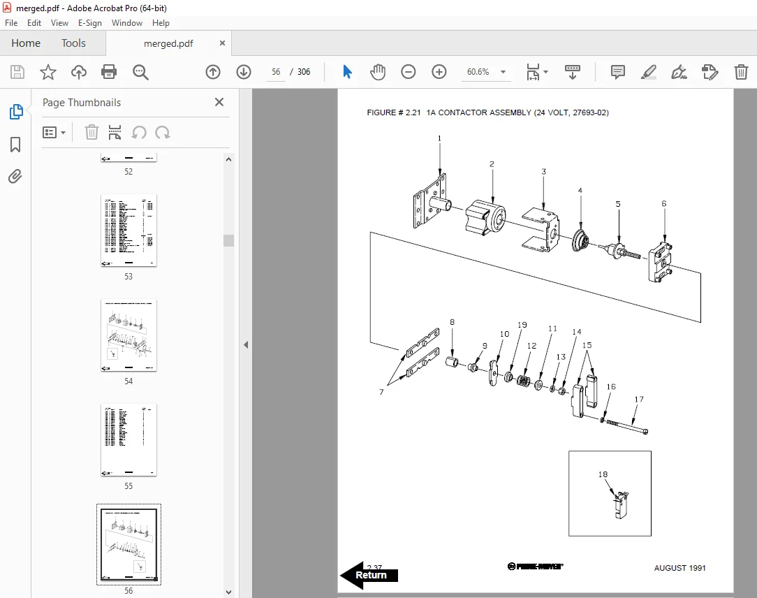
Figure # 2 21 1A Contactor Assembly 56
Figure # 2 22 High Speed Contactor Assembly 58
Figure # 2 23 Transistor Power Connector Assembly 60
Figure # 2 24 Hydraulic Pump Motor Assembly 62
Figure # 2 25 Drive Motor Assembly 64
Figure # 3 1 Hydraulic Schematic 66
Figure # 3 2 Hydraulic Schematic Symbols 67
Figure # 3 3 Resistor Hydraulic System 68
Figure # 3 4 Transistor Hydraulic System 70
Figure # 3 5 Pump and Motor Assembly 72
Figure # 3 6 Lift Cylinder Assembly 74
Figure # 4 1 Shielding Assembly 76
Figure # 4 2 Carrier Frame Assembly 78
Figure # 4 3 Caster Assembly 80
Figure # 4 4 HX-80 Lift Frame Assembly 82
Figure # 4 5 Pallet Entry Rollers 84
Figure # 4 6 Skid Adapter and Package Guard Assembly 86
Figure # 4 7 Removable Load Backrest 88
Figure # 7 1 Special Tools and Lubrications 90
Numerical Index 93
Front Cover 104
Parts Ordering Instructions 105
Field Modifications 105
General Information 106
Alphabetical Index 107
Figure # 0 1 Decals and Parts Assembly 109
Figure # 0 2 Parts List Index 111
Figure # 1 1 Transmission and Handle Assembly 113
Figure # 1 2 Twist Grip Resistor & Transistor Control Handle Assembly 115
Figure # 1 3 Thumb Control Resistor & Transistor Control Handle Assembly 117
Figure # 1 4 Part 1 Transmission Assembly 119
Figure # 1 5 Part 2 Transmission Assembly 121
Figure # 2 1 Resistor Electrical Schematic 123
Figure # 2 2 Resistor Electrical Schematic Symbols 124
Figure # 2 3 Resistor Control Wiring Harness Assembly 125
Figure # 2 4 Resistor Third Speed Control Wiring 127
Figure # 2 5 Resistor Third Speed Power Component Wiring 129
Figure # 2 6 Resistor Control Panel Assembly, 24 Volt 131
Figure # 2 7 Contactor Assembly, 24 Volt 133
Figure # 2 8 Forward & Rearward Contactor Assembly, 24 Volt 135
Figure # 2 9 Third Speed Contactor Panel Assembly 137
Figure # 2 10 Fourth Speed Control Wiring 139
Figure # 2 11 Fourth Speed Power Component Wiring 141
Figure # 2 12 Fourth Speed Contactor Panel Assembly 143
Figure # 2 13 Contactor Assembly 145
Figure # 2 14 Resistor Power Connector Assembly 147
Figure # 2 15 Transistor Electrical Schematic 149
Figure # 2 16 Transistor Electrical Schematic Symbols 150
Figure # 2 17 Transistor Control Wiring Harness Assembly 151
Figure # 2 18 Transistor Power Component Wiring 153
Figure # 2 19 Control Panel Assembly, 24 Volt 155
Figure # 2 20 Forward & Rearward Contactor Assembly, 24 Volt 157
Figure # 2 21 1A Contactor Assembly, 24 Volt 159
Figure # 2 22 High Speed Contactor Assembly, 24 Volt 161
Figure # 2 23 Transistor Power Connector Assembly 163
Figure # 2 24 Pump Motor Assembly, 24 Volt 165
Figure # 2 25 Drive Motor Assembly 167
Figure # 3 1 Hydraulic Schematic 169
Figure # 3 2 Hydraulic Schematic Symbols 170
Figure # 3 3 Resistor Hydraulic System 171
Figure # 3 4 Transistor Hydraulic System 173
Figure # 3 5 Pump and Motor Assembly 175
Figure # 3 6 Lift Cylinder Assembly 177
Figure # 4 1 Shielding Assembly 179
Figure # 4 2 Carrier Frame Assembly 181
Figure # 4 3 Caster Assembly 183
Figure # 4 4 Lift Frame Assembly 185
Figure # 4 5 Pallet Entry Rollers 187
Figure # 4 6 Skid Adapter and Package Guard Assembly 189
Figure # 4 7 Removable Load Backrest 191
Figure # 10 1 Special Tools and Lubrications 193
Numerical Index 196
Front Cover 205
Parts Ordering Instructions 206
General Information 207
Alphabetical Index 208
Section 0 0 210
Figure # 0 1 210
Figure # 0 2 212
Section 1 0 214
Figure # 1 1 214
Figure # 1 2 216
Figure # 1 3 218
Figure # 1 4 220
Figure # 1 5 222
Section 2 0 224
Figure # 2 1 224
Figure # 2 2 225
Figure # 2 3 226
Figure # 2 4 228
Figure # 2 5 230
Figure # 2 6 232
Figure # 2 7 234
Figure # 2 8 236
Figure # 2 9 238
Figure # 2 10 240
Figure # 2 11 242
Figure # 2 12 244
Figure # 2 13 246
Figure # 2 14 248
Figure # 2 15 250
Figure # 2 16 251
Figure # 2 17 252
Figure # 2 18 254
Figure # 2 19 256
Figure # 2 20 258
Figure # 2 21 260
Figure # 2 22 262
Figure # 2 23 264
Figure # 2 24 266
Figure # 2 25 268
Section 3 0 270
Figure # 3 1 270
Figure # 3 2 271
Figure # 3 3 272
Figure # 3 4 274
Figure # 3 5 276
Figure # 3 6 278
Section 4 0 280
Figure # 4 1 280
Figure # 4 2 282
Figure # 4 3 284
Figure # 4 4 286
Figure # 4 5 288
Figure # 4 6 290
Figure # 4 7 292
Section 10 0 294
Figure # 10 1 294
Numerical Index 297
DESCRIPTION:
BT Prime-Mover HX 80 Electric Low Lift Pallet Truck Parts Manual – PDF DOWNLOAD
Manual Number 9108
Manual Part Number 301441-000
PARTS ORDERING INSTRUCTIONS:
HOW TO ORDER:
- When you order, supply the part number, quantity, model and serial numbers of your machine. Supplying this information will assure prompt, efficient handling of your order. The pictorial reference number is not needed and including it can only add confusion.
- Since your dealer carries many parts in stock and maintains up-to-date prices on all parts, he will be able to process your order immediately. If, for some reason, the part is not in stock, he will order it from the factory. In either event, he maintains a current file of service manuals, which give all available parts ordering or technical information.
- All prices are FOB factory in Muscatine, Iowa. Shipping charges are added to the price of the part shipping from the factory.
WHERE TO ORDER:
Always order parts from the dealer who sold you your BT PRIME-MOVER. If it is necessary for the dealer to order parts from the factory, he is able to get prompt service for you. Parts are shipped in accordance with shipping instructions given on the order.
S.V 21/01/2025