BT Prime-Mover PE-60C HT-60C Center Control Low Lift Parts Manual PDF
$28.95
BT Prime-Mover PE-60C HT-60C Center Control Low Lift Parts Manual – PDF DOWNLOAD
Description
BT Prime-Mover PE-60C HT-60C Center Control Low Lift Parts Manual – PDF DOWNLOAD
FILE DETAILS:
BT Prime-Mover PE-60C HT-60C Center Control Low Lift Parts Manual – PDF DOWNLOAD
Language : English
Pages : 235
Downloadable : Yes
File Type : PDF
IMAGES PREVIEW OF THE MANUAL:
TABLE OF CONTENTS:
BT Prime-Mover PE-60C HT-60C Center Control Low Lift Parts Manual – PDF DOWNLOAD
Front Cover 2
Warranty 3
Parts Ordering Instructions 4
General Information 5
Figure # 1 Decal and Parts Assembly 7
Figure # 2 Parts List and Service Reference Index 9
Figure # 3 Shield Assembly 11
Figure # 4 Transmission and Handle Assembly 13
Figure # 5 Tee Handle Assembly 15
Figure # 6 3 Speed Master Control Switch Assembly 17
Figure # 7 4 Speed Master Control Handle Assembly 19
Figure # 8 PE-60C 22:1 Transmission Assembly 21
Figure # 9 PE-60C 22:1 Drive Motor Assembly 23
Figure # 10 Drive Motor 12 Volt 25
Figure # 11 Drive Motor 24 Volt 27
Figure # 12 HT-60C 14:1 Transmission Assembly 29
Figure # 13 Drive Motor 24 Volt 31
Figure # 14 PE-60C Electrical Schematic 33
Figure # 15 HT-60C Electrical Schematic 34
Figure # 16 Electrical Schematic Symbols 35
Figure # 17 PE-60C 3 Speed Control Wiring Harness 37
Figure # 18 12 Volt PE-60C 3 Speed Power Components 39
Figure # 19 24 Volt PE-60C 3 Speed Power Components 41
Figure # 20 PE-60C Control Panel Assembly 43
Figure # 21 GE Contactor Assembly 45
Figure # 22 GE Contactor Assembly 47
Figure # 23 PE-60C 3 Speed Panel Assembly 49
Figure # 24 HT-60C 3 Speed Control Wiring Harness 51
Figure # 25 HT-60C 3 Speed Power Components 53
Figure # 26 HT-60C Control Panel Assembly 55
Figure # 27 GE Contactor Assembly 57
Figure # 28 HT-60C 3 Speed Panel Assembly 59
Figure # 29 HT-60C 4 Speed Control Wiring Harness 61
Figure # 30 HT-60C 4 Speed Power Components 63
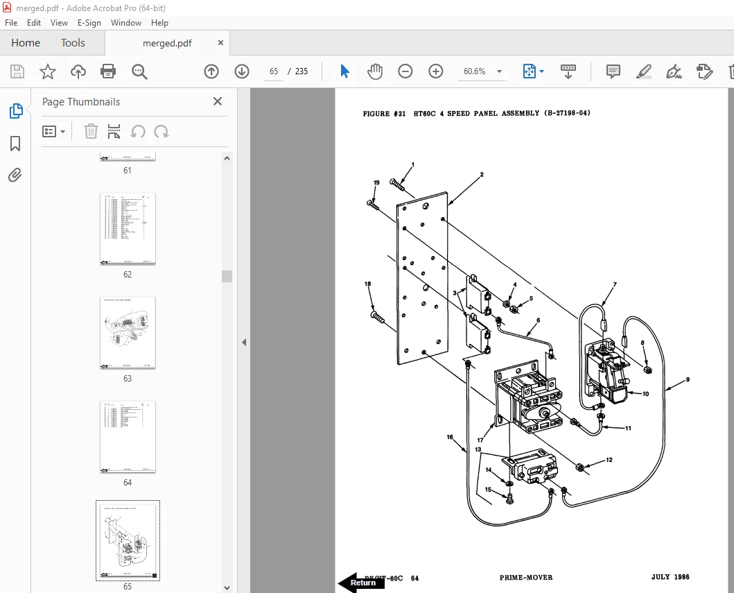
Figure # 31 HT-60C 4 Speed Panel Assembly 65
Figure # 32 Contactor Assembly 67
Figure # 33 Power Connector Assembly 69
Figure # 34 Wiring Assembly for Cold Storage 71
Figure # 35 Hydraulic Schematic 73
Figure # 36 Hydraulic Schematic Symbols 74
Figure # 37 Hydraulic System 75
Figure # 38 Hydraulic Pump and Motor Assembly 77
Figure # 39 Motor Assembly 79
Figure # 40 Cylinder Assembly 81
Figure # 41 Lift Frame Assembly 83
Figure # 42 Carrier Frame Assembly 85
Figure # 43 Spring Loaded Caster Assembly 87
Figure # 44 Pallet Entry Rollers 89
Numerical Index 91
Back Cover 101
Front Cover 102
Parts Ordering Instructions 103
General Information 104
Alphabetical Index 105
Figure # 0 1 Decals and Parts Assembly 107
Figure # 0 2 Parts List and Index 109
Figure # 1 1 PE-60C 22:1 Transmission and Handle Assembly 111
Figure # 1 2 HT-60C 14:1 Transmission and Handle Assembly 113
Figure # 1 3 Tee Handle Assembly 115
Figure # 1 4 PE-60C 22:1 Part # 1 Transmission Assembly 117
Figure # 1 5 PE-60C 22:1 Part # 2 Transmission Assembly 119
Figure # 1 6 22:1 Drive Motor Assembly 121
Figure # 1 7 HT-60C 14:1 Part #1 Transmission Assembly 123
Figure # 1 8 HT-60C 14:1 Part #2 Transmission Assembly 125
Figure # 2 1 Resistor Master Control Switch 127
Figure # 2 2 Resistor 4 Speed Master Control Switch 129
Figure # 2 3 EV-100/EV-1 SCR Master Control Switch 131
Figure # 2 4 PE-60C Resistor Electrical Schematic 133
Figure # 2 5 Resistor Electrical Schematic Symbols 134
Figure # 2 6 PE-60C Third Speed Control Wiring 135
Figure # 2 7 12 Volt PE-60C Third Speed Power Component Wiring 137
Figure # 2 8 24 Volt PE-60C Third Speed Power Component Wiring 139
Figure # 2 9 Control Panel Assembly 141
Figure # 2 10 Contactor Assembly 143
Figure # 2 11 Forward & Rearward Contactor Assembly 145
Figure # 2 12 Third Speed Contactor Panel Assembly 147
Figure # 2 13 PE-60C Third Speed Contactor Assembly 149
Figure # 2 14 HT-60C Resistor Electrical Schematic 151
Figure # 2 15 Resistor Electrical Schematic Symbols 152
Figure # 2 16 HT-60C Third Speed Control Wiring 153
Figure # 2 17 HT-60C Third Speed Power Component Wiring 155
Figure # 2 18 HT-60C Resistor Control Panel Assembly 157
Figure # 2 19 HT-60C Third Speed Contactor Panel Assembly 159
Figure # 2 20 HT-60C Fourth Speed Control Wiring 161
Figure # 2 21 HT-60C Fourth Speed Power Component Wiring 163
Figure # 2 22 HT-60C Fourth Speed Contactor Panel Assembly 165
Figure # 2 23 EV-100 SCR Trucks Electrical Schematic 167
Figure # 2 24 EV-100 SCR Truck Electrical Schematic Symbols 168
Figure # 2 25 EV-100 SCR Control Wiring 169
Figure # 2 26 HT-60C EV-100 SCR Two Speed Power Component Wiring 171
Figure # 2 27 EV-100 SCR Contactor Panel Assembly 173
Figure # 2 28 EV-100 SCR Forward & Rearward Contactor Assembly 175
Figure # 2 29 EV-100 1A Contactor Assembly 177
Figure # 2 30 HT-60C EV-100 SCR Two Speed Pump Contactor Panel Assembly 179
Figure # 2 31 EV-100 SCR Three Speed Power Component Wiring 181
Figure # 2 32 EV-100 SCR Three Speed Contactor Panel Assembly 183
Figure # 2 33 EV-100 SCR Two & Three Speed Control Panel 185
Figure # 2 34 Power Connector Assembly 187
Figure # 2 35 Hydraulic Pump Motor Assembly 189
Figure # 2 36 PE-60C Drive Motor Assembly 191
Figure # 2 37 HT-60C 14:1 Drive Motor Assembly 193
Figure # 2 38 Wiring Assembly for Cold Storage 195
Figure # 3 1 Hydraulic Schematic 197
Figure # 3 2 Hydraulic Schematic Symbols 198
Figure # 3 3 Hydraulic System 199
Figure # 3 4 Pump and Motor Assembly 201
Figure # 3 5 Lift Cylinder Assembly 203
Figure # 4 1 Shielding Assembly 205
Figure # 4 2 Carrier Frame Assembly 207
Figure # 4 3 Caster Assembly 209
Figure # 4 4 Lift Frame Assembly 211
Figure # 4 5 Pallet Entry Rollers 213
Figure # 4 6 Rider Compartment and Padding Assembly 215
Figure # 6 1 Special Tools and Lubrications 217
Numerical Index 220
Back Cover 235
DESCRIPTION:
BT Prime-Mover PE-60C HT-60C Center Control Low Lift Parts Manual – PDF DOWNLOAD
PARTS ORDERING INSTRUCTIONS:
HOW TO ORDER:
- When you order, supply the part number, quantity, model and serial numbers of your machine. Supplying this information will assure prompt, efficient handling of your order. The pictorial reference number is not needed and including it can only add confusion.
- Since your dealer carries many parts in stock and maintains up-to-date prices on all parts, he will be able to process your order immediately. If, for some reason, the part is not in stock, he will order it from the factory. In either event, he maintains a current file of service manuals, which give all available parts ordering or technical information.
- All prices are FOB factory in Muscatine, Iowa. Shipping charges are added to the price of the part shipping from the factory.
WHERE TO ORDER:
Always order parts from the dealer who sold you your Prime-Mover. If it is necessary for the dealer to order parts from the factory, he is able to get prompt service for you. Parts are shipped in accordance with shipping instructions given on the order.
S.V 02/02/2025