BT Prime-Mover PE45 PE45R PE45C PE60 PE60R PL45 HT45 HT60 Truck Operating & Parts Manual PDF
$28.95
BT Prime-Mover PE45 PE45R PE45C PE60 PE60R PL45 HT45 HT60 Truck Operating Maintenance & Parts Manual – PDF DOWNLOAD
Description
BT Prime-Mover PE45 PE45R PE45C PE60 PE60R PL45 HT45 HT60 Truck Operating Maintenance & Parts Manual – PDF DOWNLOAD
FILE DETAILS:
BT Prime-Mover PE45 PE45R PE45C PE60 PE60R PL45 HT45 HT60 Truck Operating Maintenance & Parts Manual – PDF DOWNLOAD
Language : English
Pages : 393
Downloadable : Yes
File Type : PDF
IMAGES PREVIEW OF THE MANUAL:
TABLE OF CONTENTS:
BT Prime-Mover PE45 PE45R PE45C PE60 PE60R PL45 HT45 HT60 Truck Operating Maintenance & Parts Manual – PDF DOWNLOAD
310508-000 1967_April
310504-000 1969_April
310505-000 1970_October
310506-000 1973_July
301481-000 After 1974_March
309829-000 Before 1984_August
301071-000 1984_August
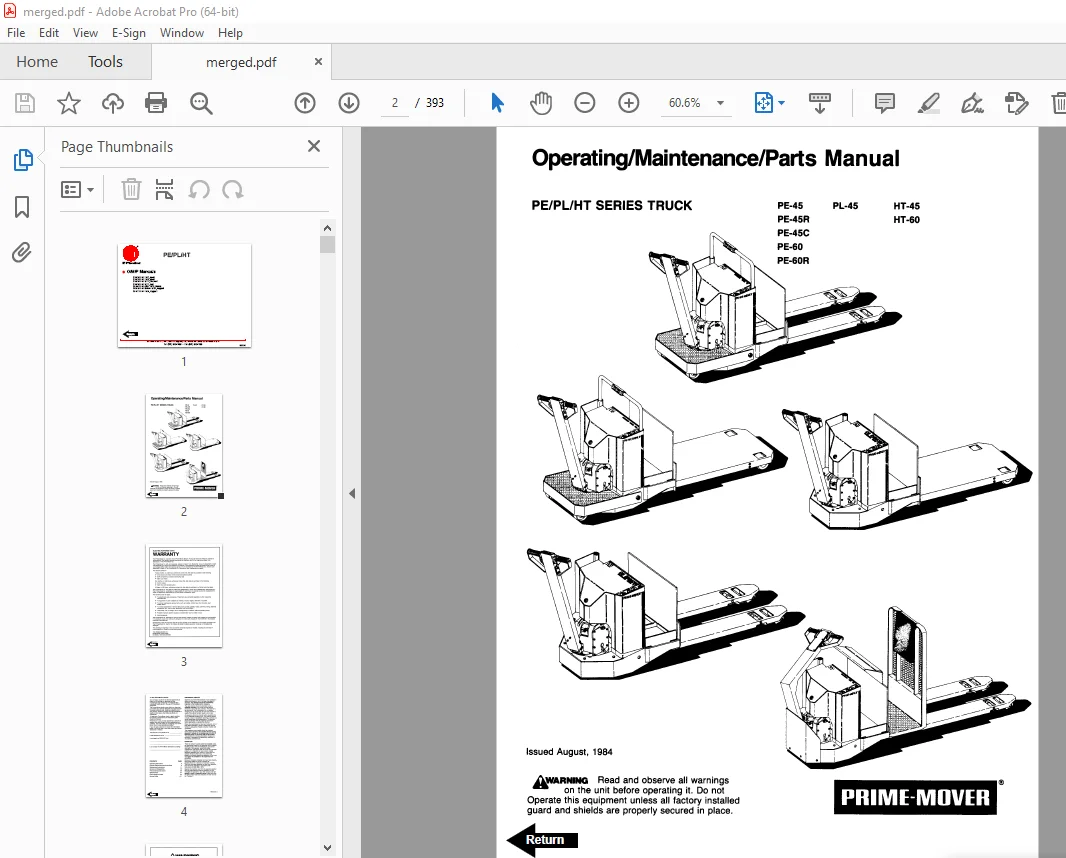
Front Cover 2
Warranty 3
To New Prime-Mover Owners 4
Preliminary Service 4
Operation 4
Warning 5
Operating Rules and Instructions 6
Operator Qualifications 6
Operator Training 6
Operator Responsibility 6
General Rules and Practices 6
Traveling 6
Loading 7
Operator Care of the Truck 7
Controls and Safety Equipment 8
Horn Switch 8
Raise Switch 8
Lower Switch 8
Third Speed Control Switch 8
Key Switch 8
Battery Discharge Indicator 8
Hourmeter 9
Safety Interlock Switch 9
Deadman Brake 9
Direction Control Handle 9
Direction Control 9
Resistor Control 9
SCR Control System 9
Periodic Maintenance Chart 10
Lubrication Chart 11
Maintenance Instructions 12
Battery 12
Theory of Electrical Operations 12
Control Switches 12
Power Wiring 12
Control Wiring 13
Lift Limit Switch 13
Mechanical Brake 13
Interlock Switch 14
Transmission Rollers 14
Contactor Points 14
Motor Commutator 14
60 Series Only Pull Rod Assembly/Adjustment 14
Hydraulic System 15
Hydraulic Pump/Motor 15
Hydraulic Filter 15
Pressure Relief Valve Adjustment 15
Service and Disassembly Instructions 16
Contactor Points 16
Flush Grease Fittings 16
Remove Handle and Transmission Assembly 16
Handle and Transmission Assembly 16
Disassembly 16
Assembly 17
Drive Wheel 17
Drive Motor 17
Assembly 17
Adjustment of Backlash for 22:1 Transmission 17
Gear Case Guide Ring 18
22:1 Transmission Assembly (Single Disc Brake Assembly) 18
Assembly of Drive Motor 18
22:1 Transmission Assembly (Multiple Disk Brake Assembly) 19
Assembly of Drive Motor 19
Mechanical Brake 20
Interlock Switch 21
Assembly of 14:1 Transmission 21
Directional Control Switch 23
Master Switch 23
Disassembly 23
Assembly 24
Electrical Panel Contactors 24
Disassembly 24
Assembly 24
Lift Frame 25
Hydraulic Pump 25
Release Valve and Solenoid 25
Hydraulic Cylinders 25
Contactor Assembly 25
Connections 25
Maintenance and Adjustment 25
Power Contacts 25
Disassembly 25
Inspection 26
Assembly 26
Parts Ordering Instructions 27
Field Modifications 27
PE-45 Electric Low Lift Pallet Truck Specifications 28
PE-45R Electric Low Lift Pallet Truck Specifications 29
PE-60 Electric Low Lift Pallet Truck Specifications 30
PE-60R Electric Low Lift Pallet Truck Specifications 31
HT-45 Electric End Controlled Low Lift Pallet Truck Specifications 32
HT-60 Electric End Controlled Low Lift Pallet Truck Specifications 33
Parts Information 34
Figure 1 Decal and Parts Assembly 34
Figure 2 Part List and Service Reference Index 35
Figure 3 Shield Assembly 37
Figure 4 PE45C Frame Components 38
Figure 5 PE45/60 Carrier Frame Assembly 39
Figure 6 PE45/60 22:1 Handle and Transmission Assembly 40
Figure 7 PE45C 22:1 Transmission and Handle Assembly 41
Figure 8 PE45/50 Handle Assembly 42
Figure 9 PE45C Handle Assembly 43
Figure 10 Master Control Switch Assembly 44
Figure 11 Master Control Switch Assembly 45
Figure 12 Master Control Switch Assembly 46
Figure 13 Master Control Switch Assembly 47
Figure 14 PE45/60 12 Volt 22:1 Transmission Assembly Part # 1 48
Figure 15 PE45/60 12 Volt 22:1 Transmission Assembly Part # 2 49
Figure 16 Drive Motor Assembly 50
Figure 17 12 Volt Drive Motor Assembly 51
Figure 18 24 Volt Drive Motor 52
Figure 19 PE45/60 24 Volt and PE45R/60R 12/24 Volt Multiple Disc Brake Transmission Assembly 53
Figure 20 Drive Motor Assembly 55
Figure 21 Drive Motor, 12 Volt 56
Figure 22 Drive Motor, 12 Volt 57
Figure 23 HT45/60 Transmission and Handle Assembly 58
Figure 24 HT45C 14:1 Transmission and Handle Assembly 59
Figure 25 HT45/80 14:1 Transmission Assembly with MEA-4023 Drive Motor 61
Figure 26 14:1 Motor Assembly 63
Figure 27 Spring Loaded Caster Assembly 64
Figure 28 Electrical Symbols 65
Figure 29 PE/PL Electrical Schematic 66
Figure 30 Control Wiring Harness Assembly 67
Figure 31 Riding Control Wiring Harness Assembly 68
Figure 32 PE/PL Power Component Assembly 69
Figure 33 Control Panel Assembly 70
Figure 34 G E Contactor Assembly 71
Figure 35 G E Contactor Assembly 72
Figure 36 3rd Speed Panel Assembly 73
Figure 37 Cableform 3rd Speed Panel Assembly 74
Figure 38 Contactor Assembly (Cableform) 75
Figure 39 HT45 & 60 Electrical Schematic 76
Figure 40 Control Wiring Harness Assembly 77
Figure 41 HT45/60 Riding Control Wiring 78
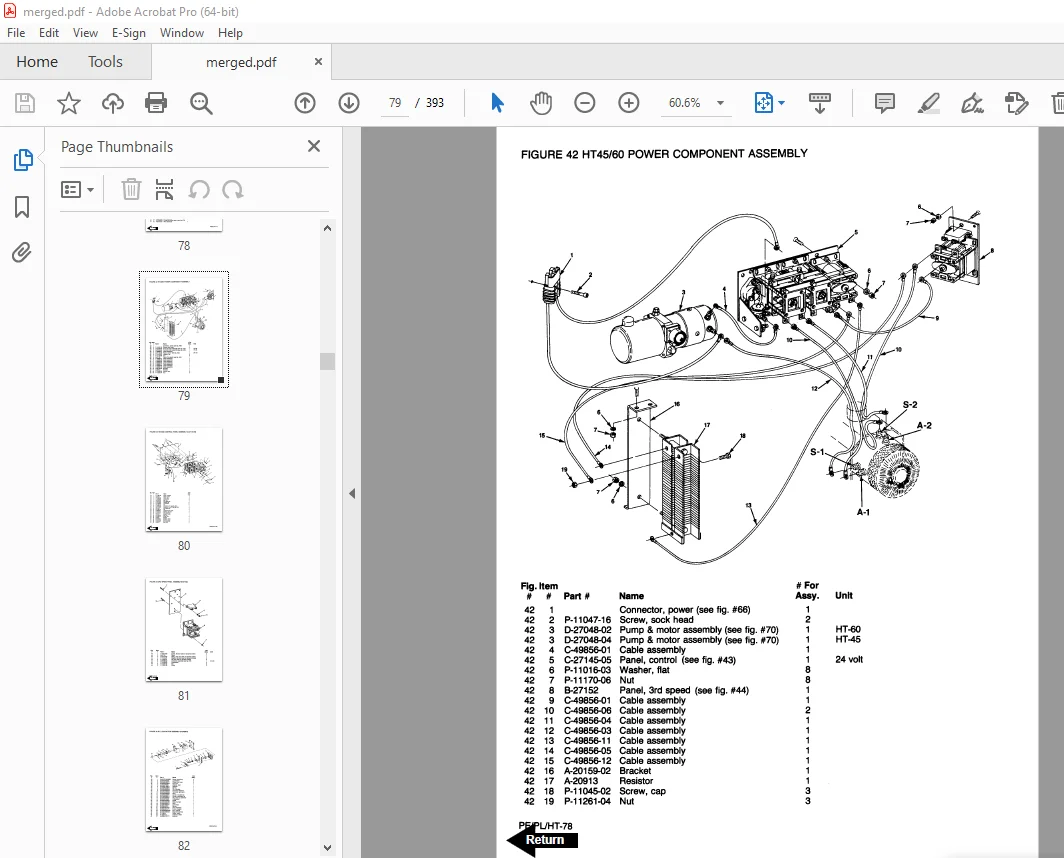
Figure 42 HT45/60 Power Component Assembly 79
Figure 43 HT45/60 Control Panel Assembly 80
Figure 44 3rd Speed Panel Assembly 81
Figure 45 G E Contactor Assembly 82
Figure 46 Dynamic Brake Control Wiring Assembly 83
Figure 47 Model 50 SCR, 24 Volt, Electrical Schematic 84
Figure 48 G E Model 50 SCR Contactor Panel Wiring Diagram 85
Figure 49 G E Model 50 SCR Panel Wiring Diagram 86
Figure 50 G E Model 50 SCR Control Wiring 87
Figure 51 Model 50 SCR Power Wiring (24 Volt) 88
Figure 52 Model 50 SCR Panel Assembly 89
Figure 53 Model SCR Contactor Panel 90
Figure 54 G E Model SCR Contactor – Forward/Reverse & 1A 91
Figure 55 Pump Cont Panel Assembly 92
Figure 56 EV-1 SCR Electrical Schematic 93
Figure 57 Model EV-1 Control Wiring Harness Assembly 94
Figure 58 EV-1 Power Component Assembly 95
Figure 59 EV-1 Contactor Panel Assembly 96
Figure 60 G E Contactor Assembly 97
Figure 61 G E Contactor Assembly 98
Figure 62 EV-1 Pump Contactor Panel 99
Figure 63 EV-1 SCR Control 100
Figure 64 Transformer Assembly 101
Figure 65 Rectifier Heat Sink Assembly 102
Figure 66 Power Connector Assembly 103
Figure 67 Hydraulic Schematic 104
Figure 68 Hydraulic Schematic Symbols 105
Figure 69 Hydraulic System 106
Figure 70 Hydraulic Pump and Motor Assembly 107
Figure 71 Motor Assembly 109
Figure 72 Cylinder Assembly 110
Figure 73 PE-45, PE-45C, PE-45R, HT-45 Lift Frame Assembly 111
Figure 74 PE-60, HT-60 Lift Frame Assembly 113
Figure 75 PL-45 Lift Frame Assembly 116
Figure 76 Foot Pedal Assembly 117
Figure 77 Pallet Entry Roller Assembly 118
Figure 78 PE/HT 45 & 60 Rider Platform 119
Figure 79 Skid Adapter and Package Guard Assembly 120
Figure 80 Removable Load Bucket Rest 121
Service Guide 122
Back Cover 125
Front Cover 126
Warranty 127
New Owners 128
Contents 128
Operating Instructions 129
Service References 130
Periodic Maintenance Chart 131
Lubrication Chart 131
Maintenance Instructions 132
Theory of Electrical Operations 132
Battery 132
Power Wiring 132
Control Wiring 132
Control Switches 133
Lift Limit Switch 133
Mechanical Brake 133
Interlock Switch 134
Transmission Rollers 134
Contactor Points 134
Motor Commutator 134
Theory of Operation Hydraulic System 135
Hydraulic Pump/motor 135
Release Valve and Solenoid 135
Hydraulic Filter 135
Pressure Relief Valve Adjustment 135
Service and Dissassembly Instructions 137
Handle 137
Direction Control Switches 137
Transmission 137
Drive Motor 137
Grive Gear Adjustment 137
Lift Frame 138
Electrical Control Panel 138
Hydraulic Pump 138
Hydraulic Cylinders 138
Gear Case Guide Ring 138
Parts Ordering Instructions 139
How to Order 139
Where to Order 139
Instructions for Returning Parts 139
Field Modifications 139
Major Components 141
Parts List Index 142
Carrier Frame Components for PE/PL 40 143
Carrier Frame Components for PE/PL 60 144
Lift Linkage for PE 40 145
Lift Linkage for PL 40 146
Lift Linkage for PE/PL 60 147
12 Volt Transmission 149
24 Volt Transmission 151
Drive Motor 12 and 24 Volt 153
Control Handle – Lower assembly for PE/PL 40/60 155
Control Handle – Lower assembly PE/PL 40/60C 156
Control Handle – Upper 157
Wiring Diagram 159
Electrical Control Panel 160
Power Wiring 161
Control Wiring 162
Hydraulic Piping 163
Hydraulic Cylinder PE/PL 40 164
Hydraulic Cylinder PE/PL 60 165
12 Volt Hydraulic Motor 167
24 Volt Hydraulic Motor 168
Stone Hydraulic Pump Parts 169
Skid Adapter 171
Center Control Wiring for PE\PL 40/60C 172
40 Series High Speed Rider for PE/PL 40R 173
60 Series High Speed Rider for PE/PL 60R 174
Service Guide 175
Back Cover 177
Front Cover 178
Warranty 179
New Owners 180
Contents 180
Specifications for Trucks 180
Operating Rules and Instructions 181
Maintenance Instructions 185
Service and Disassembly Instructions 189
Parts Ordering Instructions 191
Parts List and Service Reference Index 192
Shielding 193
Pe 40C Frame Components 194
PE/PL/HT 45 & 45C Carrier Frame 195
PE/PL/HT 60 Carrier Frame 197
PE45/C/R HT45 Lift Frame Assembly 199
PE/HT 60 Lift Frame Assembly 201
PL45/PL45R Platform Assembly 204
22:1 Spur Gear Transmission 205
24 Volt PE Drive Motor for P-22228 207
PE Drive Motor for P-20845 208
PE Drive Motor for D-20513 209
PE Drive Motor for P-20843 210
HT 45 & 60 14:1 Transmission 213
HT 45 & 60 24 Volt, Drive Motor for P-25901 215
PE 45C Control Handle Assembly 217
PE/HT 45 & 60 Control Handle Assembly 219
PE/PL Electrical Schematic 221
PE 45 & 60 Control Wiring 222
PE 45R & 60R Control Wiring 223
Power Wiring Assembly 224
HT 45 & 60 Electrical Schematic 225
HT 45 & 60 Control Wiring 226
HT 45 & 60 Power Wiring Diagram 227
Electrical Control Panel/3rd Speed Panel 228
Square “D” Forward/Reverse and 2nd/3rd Speed Contactors 229
Pe 45C 3rd Speed Foot Switch Assembly 231
PE 45C Control Wiring 232
Dynamic Brake 233
Control Switch Assembly for Resistor 234
Control Switch Assembly for SCR 235
Model 50 SCR, 24 Volt, Electrical Schematic 236
G E Model 50 SCR Control Wiring 237
G E Model 50 SCR Power Wiring 238
G E Model 50 SCR Contactor Panel 239
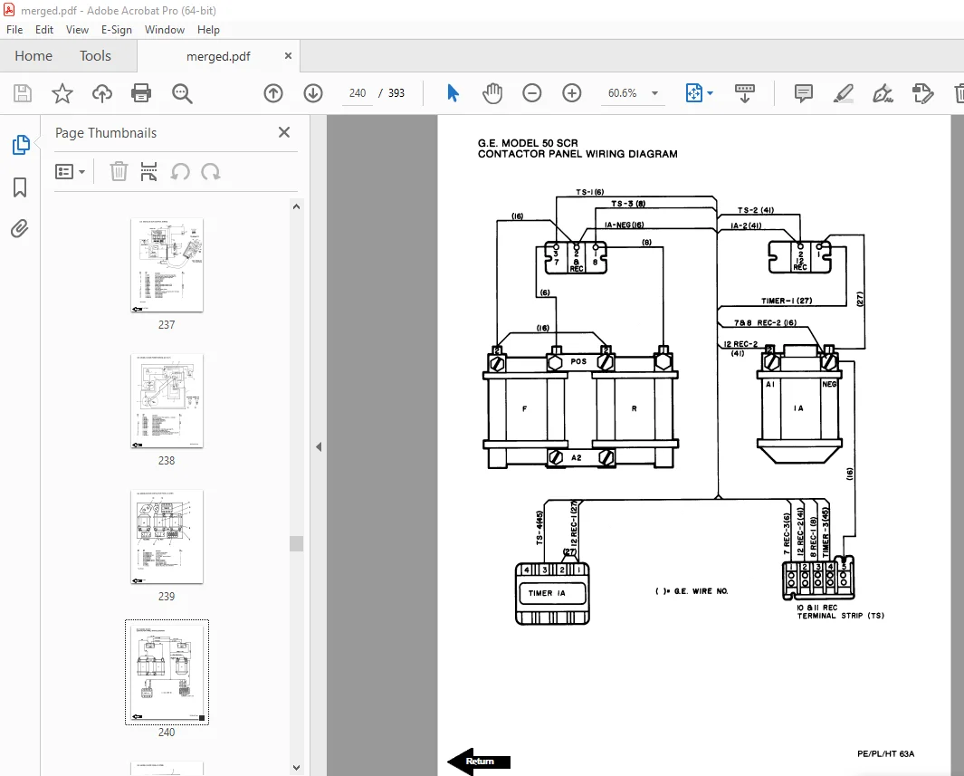
G E Model 50 SCR Contactor Panel Wiring Diagram 240
G E Model 50 SCR Panel 241
G E Model 50 SCR Panel Wiring Diagram 242
G E Model 50 SCR Contactor – Forward/Reverse & 1A 243
Pump Contactor Panel Assembly 244
Model EV-1 SCR Electrical Schematic 245
Model EV-1 Control Wiring 246
Model EV-1 Power Wiring 247
G E Model EV-1 SCR Control Panel 248
Model EV-1 Contactor Panel 249
HT EV-1 Pump Contactor Panel 250
EV-1 Forward/Reverse Contactor 251
EV-1 1A, Contactor 253
Hydraulic Diagram 255
PE/HT Hydraulic Pump & Motor Assembly 256
PE/HT Hydraulic Pump Motor 257
Lift Cylinder 258
Pallet Entry Pollers 259
PE/HT 45 & 60 Rider Platform 260
PE/HT Options 261
Service Guide 263
Back Cover 265
Front Cover 266
Warranty 267
Contents 268
To New Prime-Mover Owners 268
Operating Instructions 269
Preliminary Service 269
Controls 269
Safety Interlock 269
Lift/Lower 269
Direction Control 269
Deadman Brake 269
Key Switch (Optional) 269
Horn 270
Dynamic Brake (Optional) 270
Operator Maintenance 270
Battery Care 270
Maintenance Instructions 271
Battery 271
Power Wiring 271
Control Wiring 271
Control Switches (Handle) 272
Limit Switch Adjustment (Lift) 272
Mechanical Brake 272
Interlock Switch 273
Transmission Rollers 273
Contactor Points 274
Motor Commutator 274
Hydraulic System 274
Service Instructions 275
Parts Ordering Instructions 275
Parts List Index 276
Control Handle 277
Drive Motor and Transmission Mounting 278
Transmission Assembly 280
Carrier Frame 281
Lift Frame and Linkage 282
Electrical Control Panel 283
Power Wiring 284
Hydraulic Piping Diagram 285
Hydraulic Cylinder Assembly 285
Hydraulic Pump Parts List 286
Brake Linkage and Interlock Switch 287
Control Wiring 288
Control Switch Installation 289
Lift Platform and Linkage 290
High Speed Rider 291
Skid Adapter 292
Wiring Diagram, Horn 293
Wiring Diagram, Dyn Brake 293
Wiring Diagram, Hour Meter, and Key Switch (Optional) 294
Service Guide 295
Front Cover 298
Prime-Mover Warranty 299
Contents 300
To New Prime-Mover Owners 300
Operating Instructions 301
Preliminary Service 301
Controls 301
Safety Interlock 301
Lift/Lower 301
Direction Control 301
Deadman Brake 301
Key Switch (Optional) 301
Horn (Optional) 302
Dynamic Brake (Optional) 302
Operator Maintenance 302
Battery Care 302
Maintenance Instructions 303
Battery 303
Power Wiring 303
Control Wiring 303
Control Switches (Handle) 304
Limit Switch Adjustment (Lift) 304
Mechanical Brake 304
Interlock Switch 305
Transmission Rollers 305
Contactor Points 305
Motor Commutator 306
Hydraulic System 306
Service Instructions 307
Parts Ordering Instructions 307
Parts List Index 308
Control Handle 309
Drive Motor and Transmission Mounting 310
Motor Service Parts 310
Transmission Assembly 312
Carrier Frame 313
Lift Frame and Linkage 314
Electrical Control Panel 315
Power Wiring 316
Hydraulic Piping Diagram 317
Hydraulic Cylinder Assembly 317
Hydraulic Pump Parts List 318
Motor Service Parts 318
Brake Linkage and Interlock Switch 319
Control Wiring 320
Control Switch Installation 321
Lift Platform and Linkage 322
High Speed Rider 323
Skid Adapter 324
Wiring Diagram, Horn 325
Wiring Diagram, Dyn Brake 325
Wiring Diagram, Hour Meter, and Key Switch (Optional) 326
Service Guide 327
Front Cover 330
Prime-Mover Warranty 332
Contents 333
To New Prime-Mover Owners 333
Operating Instructions 334
Preliminary Service 334
Controls 334
Safety Interlock 334
Lift/Lower 334
Direction Control 334
Deadman Brake 334
Key Switch (Optional) 334
Horn 334
Dynamic Brake (Optional) 334
Field Weakening (Optional Over-Speed) 334
Operator Inspection and Maintenance Procedures 334
Maintenance Instructions 335
Battery 335
Power Wiring 335
Control Wiring 335
Control Switches (Handle) 336
Mechanical Brake 336
Interlock Switch 336
Transmission Rollers 336
Contactor Points 336
Motor Commutator 337
Hydraulic System 337
Service and Disassembly Instructions 337
Handle 337
Direction Control Switches 337
Transmission 337
Drive Motor 338
Drive Gear Adjustment 338
Lift Frame 338
Electric Control Panel 338
Hydraulic Pump 338
Hydraulic Cylinders 338
Gear Case Guide Ring 338
Parts Ordering Instructions 338
Parts List Index 339
Frame Fittings 341
Wheel Fork and Pull Rod 342
Control Handle 344
Transmission Assembly 12 Volt 348
Drive Motor Service Parts 348
Transmission Assembly 24 Volt 350
Drive Motor Service Parts 350
Electrical Control Panel 351
Power Wiring 352
Control Wiring 353
High Speed Rider 354
Hydraulic Piping Diagram 357
Hydraulic Cylinder Assembly 358
Hydraulic Pump Parts List 359
Motor Service Parts 12 Volt 360
Motor Service Parts 24 Volt 360
Skid Adapter 361
Service Guide 362
Back Cover 365
Front Cover 366
Prime-Mover Warranty 367
Contents 368
To New Prime-Mover Owners 368
Operating Instructions 369
Preliminary Service 369
Controls 369
Safety Interlock 369
Direction Control 369
Deadman Brake 369
Key Switch (Optional) 369
Horn (Optional) 370
Dynamic Brake (Optional) 370
Operator Maintenance 370
Battery Care 370
Maintenance Instructions 371
Battery 371
Power Wiring 371
Control Wiring 371
Control Switches (Handle) 372
Limit Switch Adjustment (Lift) 372
Mechanical Brake 372
Interlock Switch 373
Transmission Rollers 373
Contactor Points 374
Motor Commutator 374
Hydraulic System 374
Service Instructions 375
Parts Ordering Instructions 375
Parts List Index 376
Control Handle 377
Drive Motor and Transmission Mounting 378
Motor Service Parts 378
Transmission Assembly 380
Carrier Frame 381
Lift Frame and Linkage 382
Electrical Control Panel 383
Power Wiring 384
Hydraulic Piping Diagram 385
Hydraulic Cylinder Assembly 385
Hydraulic Pump Parts List 386
Brake Linkage and Interlock Switch 387
Control Wiring 388
Control Switch Installation 389
Service Guide 391
DESCRIPTION:
BT Prime-Mover PE45 PE45R PE45C PE60 PE60R PL45 HT45 HT60 Truck Operating Maintenance & Parts Manual – PDF DOWNLOAD
OPERATING RULES AND INSTRUCTIONS
OPERATOR QUALIFICATIONS
Only trained and authorized operators shall be permitted to operate a powered industrial truck. Operators of powered industrial trucks shall be qualified as to visual, auditory, physical, and mental ability to operate the equipment.
OPERATOR TRAINING
An effective operator training program should center around user company’s policies, operating conditions and trucks. The program should be presented completely to all new operators and not condensed for those claiming previous experience.
OPERATOR RESPONSIBILITY
Powered industrial truck operators shall abide by the following rules and practices.
GENERAL RULES AND PRACTICES
A. Safeguard the pedestrians at all times. Do not drive a truck up to anyone standing in front of a bench or other fixed object.
B. Do not allow anyone to stand or pass under the elevated portion of any truck, whether loaded or empty.
C. Unauthorized passengers shall not be permitted to ride.
D. Do not put any part of the body between the uprights of the mast or outside the running lines of the truck.
E. When the operator is dismounted and within 25 feet (7.60 m) of the truck which remains in his view the load engaging means shall be fully lowered, controls neutralized and brakes set to prevent movement.
F. A powered industrial truck is unattended when the operator is 25 feet (7.60 m) or more from the truck which remains in view, or whenever the operator leaves the truck and it is not in his view.
S.V 02/02/2025