BT Prime-Mover PMX-2 Low Lift Pallet Truck Spare Parts Manual PDF
$28.95
BT Prime-Mover PMX-2 ELECTRIC LOW LIFT PALLET TRUCK Parts Manual – PDF DOWNLOAD
Manual Number 9108
Manual Part Number 301468-000
301468-000 1991_August
1992_May Manual Update Pages
301468-001 1992_June
301468-002 1992_August
301468-003 1993_August
Description
BT Prime-Mover PMX-2 ELECTRIC LOW LIFT PALLET TRUCK Parts Manual – PDF DOWNLOAD
FILE DETAILS:
BT Prime-Mover PMX-2 ELECTRIC LOW LIFT PALLET TRUCK Parts Manual – PDF DOWNLOAD
Language : English
Pages : 312
Downloadable : Yes
File Type : PDF
IMAGES PREVIEW OF THE MANUAL:
TABLE OF CONTENTS:
BT Prime-Mover PMX-2 ELECTRIC LOW LIFT PALLET TRUCK Parts Manual – PDF DOWNLOAD
Manual Number 9108
Manual Part Number 301468-000
301468-000 1991_August
1992_May Manual Update Pages
301468-001 1992_June
301468-002 1992_August
301468-003 1993_August
Front Cover 8
Parts Ordering Instructions 9
General Information 10
Alphabetical Index 11
Section 0 0 13
Figure # 0 1 13
Figure # 0 2 15
Section 1 0 17
Figure # 1 1 17
Figure # 1 2 19
Figure # 1 3 21
Figure # 1 4 23
Section 2 0 25
Figure # 2 1 25
Figure # 2 2 26
Figure # 2 3 27
Figure # 2 4 29
Figure # 2 5 31
Figure # 2 6 33
Figure # 2 7 35
Figure # 2 8 37
Figure # 2 9 39
Figure # 2 10 41
Figure # 2 11 43
Figure # 2 12 45
Figure # 2 13 47
Section 3 0 49
Figure # 3 1 49
Figure # 3 2 50
Figure # 3 3 51
Figure # 3 4 53
Figure # 3 5 55
Section 4 0 57
Figure # 4 1 57
Figure # 4 2 59
Section 5 0 61
Figure # 5 1 61
Figure # 5 2 63
Figure # 5 3 65
Figure # 5 4 67
Section 7 1 69
Figure # 7 1 69
Numerical Index 72
Back Cover 79
Front Cover 80
Parts Ordering Instructions 81
Field Modifications 81
General Information 82
Alphabetical Index 83
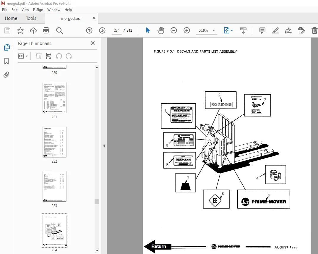
Figure # 0 1 Decals and Parts List Assembly 85
Figure # 0 2 Parts List Index 87
Figure # 1 1 Handle and Transmission Installation 89
Figure # 1 2 Twist Grip Control Handle Assembly 91
Figure # 1 3 Thumb Control Handle Assembly 93
Figure # 1 4 Transmission Assembly 95
Figure # 2 1 Electrical Schematic 97
Figure # 2 2 Electrical Schematic Symbols 98
Figure # 2 3 Control Wiring Assembly 99
Figure # 2 4 Power Component Assembly 101
Figure # 2 5 Control Panel Assembly 103
Figure # 2 6 Forward and Rearward Contactor Assembly 105
Figure # 2 7 High Speed Contactor Assembly 107
Figure # 2 8 Power Connector Assembly 109
Figure # 2 9 12 Volt, Drive Motor Assembly 111
Figure # 2 10 Drive Motor Assembly 113
Figure # 2 11 Pump Motor Assembly 115
Figure # 3 1 Hydraulic Schematic 117
Figure # 3 2 Hydraulic Schematic Symbols 118
Figure # 3 3 Hydraulic System Assembly 119
Figure # 3 4 Lift Cylinder Assembly & Cold Storage Lift Cylinder Assembly 121
Figure # 3 5 Hydraulic Pump and Motor Assembly 123
Figure # 4 1 Shielding Assembly 125
Figure # 4 2 Lift Frame and Carrier Frame Assembly 127
Figure # 5 1 Battery Pack 129
Figure # 5 2 Battery Pack Cable Assembly 131
Figure # 5 3 Battery Pack Connector Assembly 133
Figure # 5 4 Battery Blocks 135
Figure # 10 1 Special Tools and Lubrications 137
Numerical Index 140
Back Cover 146
Front Cover 147
Parts Ordering Instructions 148
General Information 149
Alphabetical Index 150
Section 0 0 152
Figure # 0 1 152
Figure # 0 2 154
Section 1 0 156
Figure # 1 1 156
Figure # 1 2 158
Figure # 1 3 160
Figure # 1 4 162
Figure # 1 5 164
Figure # 1 6 166
Section 2 0 168
Figure # 2 1 168
Figure # 2 2 169
Figure # 2 3 170
Figure # 2 4 172
Figure # 2 5 174
Figure # 2 6 176
Figure # 2 7 178
Figure # 2 8 180
Figure # 2 9 181
Figure # 2 10 182
Figure # 2 11 184
Figure # 2 12 186
Figure # 2 13 188
Figure # 2 14 190
Figure # 2 15 192
Figure # 2 16 194
Figure # 2 17 196
Section 3 0 198
Figure # 3 1 198
Figure # 3 2 199
Figure # 3 3 200
Figure # 3 4 202
Figure # 3 5 204
Section 4 0 206
Figure # 4 1 206
Figure # 4 2 208
Section 5 0 210
Figure # 5 1 210
Figure # 5 2 212
Figure # 5 3 214
Figure # 5 4 216
Numerical Index 219
Back Cover 228
Front Cover 229
Parts Ordering Instructions 230
Field Modifications 230
General Information 231
Alphabetical Index 232
Figure # 0 1 Decals and Parts List Assembly 234
Figure # 0 2 Parts List Index 236
Figure # 1 1 Handle and Transmission Installation 238
Figure # 1 2 Resistor Twist Control Handle Assembly 240
Figure # 1 3 Transistor Twist Control Handle Assembly 242
Figure # 1 4 Resistor Thumb Control Handle Assembly 244
Figure # 1 5 Transistor Thumb Control Handle Assembly 246
Figure # 1 6 Transmission Assembly 248
Figure # 2 1 Resistor Electrical Schematic 250
Figure # 2 2 Resistor Electrical Schematic Symbols 251
Figure # 2 3 Resistor Control Wiring Assembly 252
Figure # 2 4 Resistor Power Component Assembly 254
Figure # 2 5 Resistor Control Panel Assembly 256
Figure # 2 6 Resistor Forward and Rearward Contactor Assembly 258
Figure # 2 7 Resistor High Speed Contactor Assembly 260
Figure # 2 8 Transistor Electrical Schematic 262
Figure # 2 9 Transistor Electrical Schematic Symbols 263
Figure # 2 10 Transistor Control Wiring Assembly 264
Figure # 2 11 Transistor Power Component Assembly 266
Figure # 2 12 Transistor Control Panel Assembly 268
Figure # 2 13 Transistor Forward & Rearward Contactor Assembly 270
Figure # 2 14 Power Connector Assembly 272
Figure # 2 15 12 Volt, Drive Motor Assembly 274
Figure # 2 16 24 Volt, Drive Motor Assembly 276
Figure # 2 17 Pump Motor Assembly 278
Figure # 3 1 Hydraulic Schematic 280
Figure # 3 2 Hydraulic Schematic Symbols 281
Figure # 3 3 Hydraulic System Assembly 282
Figure # 3 4 Lift Cylinder Assembly & Cold Storage Lift Cylinder Assembly 284
Figure # 3 5 Hydraulic Pump and Motor Assembly 286
Figure # 4 1 Shielding Assembly 288
Figure # 4 2 Lift Frame and Carrier Frame Assembly 290
Figure # 5 1 Battery Pack 292
Figure # 5 2 Battery Pack Cable Assembly 294
Figure # 5 3 Battery Pack Connector Assembly 296
Figure # 5 4 Battery Blocks 298
Figure # 10 1 Special Tools and Lubrications 300
Numerical Index 303
Back Cover 312
DESCRIPTION:
BT Prime-Mover PMX-2 ELECTRIC LOW LIFT PALLET TRUCK Parts Manual – PDF DOWNLOAD
301468-000 1991_August
1992_May Manual Update Pages
301468-001 1992_June
301468-002 1992_August
301468-003 1993_August
Manual Number 9108
Manual Part Number 301468-000
PARTS ORDERING INSTRUCTIONS:
HOW TO ORDER:
- When you order, supply the part number, quantity, model and serial numbers of your machine. Supplying this information will assure prompt, efficient handling of your order. The pictorial reference number is not needed and including it can only add confusion.
- Since your dealer carries many parts in stock and maintains up-to-date prices on all parts, he will be able to process your order immediately. If, for some reason, the part is not in stock, he will order it from the factory. In either event, he maintains a current file of service manuals, which give all available parts ordering or technical information.
- All prices are FOB factory in Muscatine, Iowa. Shipping charges are added to the price of the part shipping from the factory.
WHERE TO ORDER:
Always order parts from the dealer who sold you your BT PRIME-MOVER. If it is necessary for the dealer to order parts from the factory, he is able to get prompt service for you. Parts are shipped in accordance with shipping instructions given on the order.
S.V 02/02/2025