BT Prime Mover PMX & PMX-1 Electrical Low Lift Truck Repair Manual PDF
$28.95
BT Prime Mover PMX & PMX-1 Electrical Low Lift Truck Repair Manual – PDF DOWNLOAD
Effective Serial Number PMX-1 182900
Description
BT Prime Mover PMX & PMX-1 Electrical Low Lift Truck Repair Manual – PDF DOWNLOAD
FILE DETAILS:
BT Prime Mover PMX & PMX-1 Electrical Low Lift Truck Repair Manual – PDF DOWNLOAD
Language : English
Pages : 218
Downloadable : Yes
File Type : PDF
IMAGES PREVIEW OF THE MANUAL:
TABLE OF CONTENTS:
BT Prime Mover PMX & PMX-1 Electrical Low Lift Truck Repair Manual – PDF DOWNLOAD
Effective Serial Number PMX-1 182900
Front Cover 1
Table of Contents 2
Parts Ordering Instructions 4
Field Modifications 4
Safety Messages 6
Warning 8
Owner Safe Maintenance Practices 9
Component Identification 10
Grease Point Identification 12
Fill Point Identification 13
Planned Maintenance Procedures 14
Daily Inspection 14
Monthly PM Service 14
Semi-Annual Service or 500 Hours 14
Annual Service or 1000 Hours 15
Planned Maintenance Schedule 16
Specifications 18
Hydraulic Schematic 18
Hydraulic Schematic Symbols 19
Electrical Schematic 20
Electrical Schematic Symbols 21
Specifications 22
Adjustments 24
Brake Theory of Operation 24
Brake Adjustment 24
Brake Interlock Switch 24
Lift Limit Switch 24
Transmission Pivot Bearing 25
Load Wheel Shimming 25
Special Tools 26
Disassembly and Repair 28
Frame 28
Load Wheel Replacement 28
Pull Rod Bushings 28
Lift Frame Linkage and Bushings 28
Drive Tire Removal and Installation 29
Control 30
Control Handle Removal and Installation 30
Control Handle Repair 30
Master Switch Removal and Installation 30
Brake Linkage 30
Brake Shoes Removal and Installation 31
Transmission 32
Transmission Removal and Installation 32
Axle Seal Removal and Installation 32
Transmission Repair 33
Electrical 34
Contactor Tip Removal and Installation 34
Pump Motor Removal and Installation 34
Pump Motor Brush Replacement 35
Drive Motor Removal and Installation 35
Drive Motor Brush Replacement 35
Drive Motor Repair 35
Hydraulic 36
Pump Assembly Removal and Installation 36
Pump Assembly Repair 36
Cylinder Assembly Removal and Installation 38
Cylinder Assembly Repair 39
Theory of Operation Index 41
Troubleshooting Index 67
Front Cover 77
Table of Contents 79
Alphabetical Table of Contents 80
Parts Ordering Instructions 81
Field Modifications 81
Safety Messages 83
Owner Safe Maintenance Practices 83
Warning 85
Component Identification 87
Grease Points 89
Fill Points 90
Planned Maintenance Procedures 91
Why a Planned Maintenance Program? 91
Inspection Form 91
PM Schedule and Procedure 91
Planned Maintenance Schedule 93
Hydraulic Schematic 95
Hydraulic Schematic Symbols 96
Electrical Schematic 97
Electrical Schematic Symbols 98
Specifications 99
Adjustments 101
Brake Linkage and Interlock Switch 101
Brake Theory of Operation 101
Brake Adjustment 101
Brake Interlock Switch 101
Lift Limit Switch 101
Transmission Pivot Bearing Adjustment 102
Load Wheel Shimming 102
Special Tools 103
Flush Grease Fitting 103
Battery Pak Lifter 103
Bearing Installing Tool 103
Disassembly and Repair 105
Load Wheel Repair and Replacement 105
Pull Rod Bushings Removal and Replacement 105
Drive Wheel Removal and Installation 106
Control Handle Removal and Installation 107
Brake Linkage Removal and Installation 107
Brake Shoe Removal and Installation 108
Transmission Removal and Installation 109
Axle Seal Removal and Installation 109
Transmission Disassembly and Assembly 110
Pump and Motor Removal and Installation 111
Drive Motor Removal and Installation 111
Removing and Installing Reservoir and Pump 114
Hydraulic Pump Removal and Repair 115
Cylinder Assembly Removal and Installation 115
PMX-1 Theory of Operation Index 118
1 0 Theory of Operation – Lift Mode 119
2 0 Theory of Operation – Lowering Mode 123
3 0 Theory of Operation – Travel – First Speed Forward 127
4 0 Theory of Operation – Travel – Second Speed Forward 129
5 0 Theory of Operation – Third Speed – Forward 131
6 0 Theory of Operation – Travel – First Speed Reverse 134
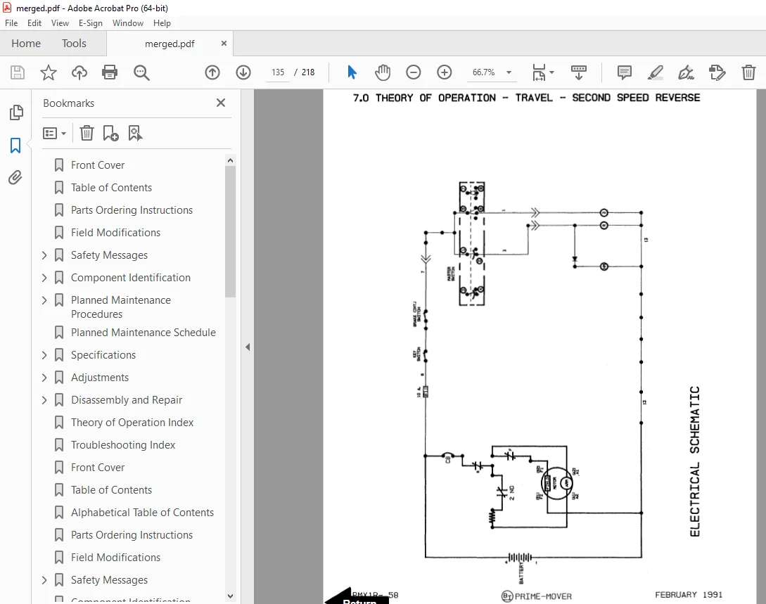
7 0 Theory of Operation – Travel – Second Speed Reverse 135
8 0 Theory of Operation – Third Speed – Reverse 137
9 0 Theory of Operation – Reverser Switch 139
10 0 Theory of Operation – Third Speed Cut-Out 141
PMX-1 Troubleshooting Index 144
1 0 Hydraulic 145
2 0 Electrical – Control Circuits 146
3 0 Electrical – Power Circuits 150
4 0 Miscellaneous Troubleshooting – Electrical 153
Charger PMX-1 Battery Pack 155
Troubleshooting the Charger Used in the BT Prime-Mover PMX-1 Battery Pack 156
Front Cover 160
Parts Ordering Instructions 161
Field Modifications 161
Safety Messages 162
Owner Safe Maintenance Practices 162
Safety Decals 163
Warning 165
Grease Points 167
Fill Points 168
Planned Maintenance Procedures 169
Inspection Form 169
PM Schedule and Procedure 169
BT Prime-Mover PMX Planned Maintenance Schedule 171
Specifications 172
Adjustments 175
Brake Linkage and Interlock Switch 175
Brake Theory of Operation 175
Brake Adjustment 175
Brake Interlock Switch 175
Lift Limit Switch 176
Transmission Pivot Bearing Adjustment 176
Load Wheel Shimming 176
Disassembly and Repair 176
Load Wheel Repair and Replacement 176
Pull Rod Bushings Removal and Replacement 176
Carrier Frame Linkage and Bushings 177
Drive Wheel Removal and Installation 177
Control Handle Removal and Installation 178
Brake Linkage Removal and Installation 179
Brake Shoe Removal and Installation 179
Transmission Removal and Installation 180
Axle Seal Removal and Installation 180
Transmission Disassembly and Assembly 181
Contactor Tip Removal and Installation 182
Pump and Motor Removal and Installation 183
Pump Motor Brush Removal and Installation 183
Drive Motor Removal and Installation 183
Drive Motor Brush Removal and Installation 184
Hydraulic Schematic 186
Hydraulic Schematic Symbols 187
Pump and Motor Removal and Installation 188
Hydraulic Pump Removal and Repair 190
Cylinder Assembly Removal Installation 191
1 0 Theory of Operation – Lift Mode 193
1 1 Hydraulics 193
1 2 Electrical 193
2 0 Theory of Operation – Lowering Mode 193
2 1 Hydraulics 193
2 2 Electrical 193
Control Wiring 194
Power Wiring 194
Control Switch 194
Electrical Schematic 195
Electrical Schematic Symbols 196
3 0 Theory of Operation – Travel – First Speed Forward 197
3 2 Electrical 197
4 0 Theory of Operation – Travel – Second Speed Forward 197
4 2 Electrical 197
5 0 Theory of Operation – Third Speed – Forward 198
5 2 Electrical 198
6 0 Theory of Operation – Travel – First Speed Reverse 199
6 2 Electrical 199
7 0 Theory of Operation – Travel – Second Speed Reverse 199
7 2 Electrical 199
8 0 Theory of Operation – Third Speed – Reverse 200
8 2 Electrical 200
9 0 Theory of Operation – Reverser Switch 201
9 2 Electrical 201
10 0 Theory of Operation – Third Speed Cut-Out 201
10 2 Electrical 201
PMX Trouble Shooting Index 202
1 0 Hydraulic 203
2 0 Electrical – Control Circuits 204
3 0 Electrical – Power Circuits 209
4 0 Miscellaneous Trouble Shooting – Electrical 212
Battery Pack Schematic 213
Troubleshooting the Charger Used in the PMX Battery Pack 214
S.V 20/01/2025