BT Prime-Mover PMX45 Electric Low Lift Pallet Truck Service Manual PDF
$28.95
BT Prime-Mover PMX45 Electric Low Lift Pallet Truck Service Manual – PDF DOWNLOAD
Description
BT Prime-Mover PMX45 Electric Low Lift Pallet Truck Service Manual – PDF DOWNLOAD
FILE DETAILS:
BT Prime-Mover PMX45 Electric Low Lift Pallet Truck Service Manual – PDF DOWNLOAD
Language : English
Pages : 282
Downloadable : Yes
File Type : PDF
IMAGES PREVIEW OF THE MANUAL:
TABLE OF CONTENTS:
BT Prime-Mover PMX45 Electric Low Lift Pallet Truck Service Manual – PDF DOWNLOAD
Standard Codes 3
Warning Symbols 13
1 Warning Levels 13
Prohibitory Symbols 14
1 Ordinance Symbols 14
Safety 15
1 General Safety 15
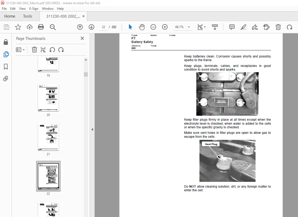
Battery Safety 19
Static Safety 24
Welding Safety 25
Introduction, Service Manual 27
Contents, Section M 29
1 Machine Information 29
General Product Information 31
1 Truck Presentation 31
1 1 Truck Side Views 31
1 1 Intended Truck Application 32
1 2 Prohibited Truck Application 32
1 3 Truck Data 32
1 4 Truck Dimensions 33
1 5 Data Plate 34
2 Main Components 35
Inch and Metric (SAE) Fasteners 37
1 Introduction 37
2 Nomenclature, Threads 38
3 Strength Identification 39
4 Conversion of English and Metric Units 46
Technical Service Data 49
Ordering Spare Parts 51
Contents, Section P 53
1 Planned Maintenance 53
Introduction, Maintenance 55
1 Jacking Truck Off The Floor 56
1 1 Elevate Rear of Truck 56
1 1 Elevate Either Side of Truck 56
2 Lubricants 57
2 1 Standard 57
2 2 Corrosion 57
2 3 Cold Storage 58
Service Schedule 61
1 Planned Maintenance Schedule 61
2 Planned Maintenance Procedures 65
2 1 Services Performed Daily or Every 8 Operating Hours 65
2 1 1 Battery Discharge Indicator with lift interrupt (optional) 65
2 1 2 Hydraulic System 65
2 1 3 Frame/Sheet Metal 66
2 1 4 Wheels/Tires 66
2 1 5 Functions/Operations 66
2 2 Services Performed Monthly or Every 120 Operating Hours 67
2 2 1 Inspection 67
2 2 2 Transmission 67
2 2 3 Brakes 67
2 2 4 Battery 67
2 2 5 Electrical Connections 68
2 2 6 Main Contactor 68
2 2 7 Motor Brushes 68
2 2 8 Drive Motor 68
2 2 9 Hydraulic Reservoir 68
2 2 10 Frame Lube 69
2 2 11 Pivot Points 69
2 3 Services Performed Every 480 or 960 Operating Hours 70
2 3 1 Drive Motor 70
2 4 Services Performed Annually or Every 1440 Operating Hours 71
2 4 1 Inspection 71
2 4 2 Transmission 71
2 4 3 Battery 71
2 4 4 Hydraulic System 72
2 4 5 Brakes 72
Lubrication Chart 73
Oil and Grease Specifications 74
1 Approved Oils and Grease 74
2 Grease Location Points 74
Contents, Section S 75
1 Service Instructions 75
Chassis/Lift Frame 77
1 Pull rod 78
1 1 Removal 78
1 2 Inspection 79
1 3 Installation 80
2 Carrier Frame Bushings 82
Inspection Covers 83
1 General Information 83
Driver Controls 87
Decals 89
1 Decal with Protective Sheet 89
2 Decal without Protective Sheet 89
Motor Maintenance Schedule/ Troubleshooting 91
1 General Information 91
2 Operating Conditions 91
3 Troubleshooting 92
Pump Motor 99
1 Mounting Points 99
1 1 Removal 99
1 2 Installation 99
2 Pump Repair 100
2 1 Disassembly 101
3 Inspection and Troubleshooting 102
3 1 Drive End Head 102
3 2 Commutator End Head 102
3 3 Bearings 102
4 Brush Inspection 103
4 1 Brush Replacement Determination 103
4 2 Replacement Procedures 104
Drive Motor 107
1 Mounting Points 107
1 1 Drive Motor Brush 108
1 2 Drive Motor Removal 108
1 3 Drive Motor Installation 110
2 Component Repair 112
2 1 Motor Disassembly 114
3 Motor Inspection 115
3 1 External Motor 115
3 2 Brush and Commutator 115
3 3 Bearings 118
3 4 Armature Electrical Check 118
3 5 Frame and Field Service Recommendation 118
3 6 Assembly/Testing 119
Transmission 121
1 System Description 121
2 Troubleshooting 121
3 Transmission Mounting 122
3 1 Wrap Around Bumper 123
3 2 Guards 124
3 3 Removal 125
3 4 Installation 126
4 Transmission Repair 127
4 1 Disassembly 128
4 2 Reassembly 129
5 Axle Seal 131
5 1 Removal 131
5 2 Installation 131
Parking Brake System 133
1 Brake Theory of Operation 134
2 Brake Adjustment 135
3 Brake Shoe Removal / Installation 136
Drive Wheel 137
1 Removal 137
2 Installation 138
3 Tire Pressing Procedure 139
Support/Swivel Wheel (Optional) 141
1 Maintenance and Adjustments 143
1 1 Caster Adjustment 143
2 Troubleshooting 143
2 1 Stabilizing Caster 143
2 1 1 Caster Replacement 143
Fork Wheels 145
1 Removal/Installation 145
Steering 147
1 Control Handle Head 148
1 1 Removal 148
1 2 Installation 148
2 Driver Protection (Reverser) Assembly Replacement 149
3 Direction Control Switches 151
3 1 Removal 151
3 2 Installation 151
4 Raise, Lower, and Horn Switches 153
4 1 Removal 153
4 2 Installation 154
5 Potentiometer 155
5 1 Removal 155
5 2 Installation 156
6 Steering Stem 160
6 1 Removal 160
6 2 Installation 160
Electrical Functions 161
1 General 161
1 1 Adjustable Settings: 161
1 2 References 161
1 3 Key Switch S17 in the ON Position 161
1 4 Operating Arm in Drive Position, S10, Brake Switch Closed 162
1 5 Travel Request, Fork First 162
1 6 Travel Request, Forks Trailing 162
1 7 Reversing/Motor Brake Forks First Direction to Forks Trailing Direction 162
1 8 Reversing/Motor Brake Forks Trailing Direction to Forks First Direction 163
1 9 Reverser switch 163
1 10 Lifting Forks 163
1 11 Lowering Forks 163
1 12 Horn 164
1 13 Lift Interrupt 164
Electrical Panel Components 165
Electrical Symbols 167
Electrical Schematics 171
Circuit Diagram 1(3) 171
Circuit Diagram 2(3) 172
Circuit Diagram 3(3) 173
Battery 175
1 Removal 175
2 Installation 175
3 Battery Maintenance 176
3 1 Battery Inspection and Care 176
3 2 Battery Exterior Cleaning 177
3 3 Charging 177
4 Storage 178
5 Battery History Record 178
Swing Out Battery Pack 179
1 Battery Cable Routing Diagram 181
2 Charger Diagram 183
3 Troubleshooting 184
3 1 Electrical Testing 184
3 1 1 Equipment required: 184
3 1 2 Instructions 184
Battery Connector 191
1 Location 191
2 Inspection 191
3 Installation 192
Battery Controller/Hourmeter/ Lift Interrupt (Optional) 193
1 General Information 193
2 Electrical 194
2 1 Voltage 194
3 Battery Controller (BC) 195
3 1 General Information 195
3 1 1 Discharge Adjustment 195
3 2 Reset 197
3 3 Key Switch 197
3 4 Hourmeter 198
4 Troubleshooting 198
4 1 Battery Discharge Indicator (BDI) 198
4 1 1 No Reset 198
4 1 2 Reset After Break in Power 198
4 1 3 No Discharge, Gauge Does Not Run Down 199
4 1 4 No Lockout 199
4 1 5 No Lift 200
4 1 6 Early Lockout 200
4 1 7 LEDs Do Not Light 200
4 2 Hourmeter 201
4 2 1 No Display 201
4 2 2 Hourmeter Glass Icon Does Not Flash 201
4 2 3 Hourmeter Glass Icon Always Flashes 201
Battery Discharge Indicator / Hourmeter 203
1 General Information 203
2 Electrical 204
2 1 Voltage 204
3 Battery Discharge Indicator (BDI) 204
3 1 General Information 204
3 2 Key Switch 204
3 3 Hourmeter 205
4 Troubleshooting 205
4 1 Battery Discharge Indicator (BDI) 205
4 1 1 No Reset 205
4 1 2 Reset After Break in Power 206
4 1 3 No Discharge, Gauge Does Not Run Down 206
4 1 4 LEDs Do Not Light 206
4 2 Hourmeter 207
4 2 1 No Display 207
4 2 2 Hourmeter Glass Icon Does Not Flash 207
4 2 3 Hourmeter Glass Icon Always Flashes 207
Start/Stop Switches 209
1 General 209
1 1 Test/Inspection 209
2 Master Control On/Off Switch (S21) 211
2 1 Inspection 211
2 2 Removal 211
2 3 Installation 211
Transistor Controller 213
1 Basics Of Circuit Operation 213
1 1 Control Features 215
2 Maintenance 216
2 1 Safety 216
2 2 Cleaning 216
3 Motor Circuit 217
4 Control Circuit 218
5 Troubleshooting Guidelines 219
5 1 General 221
6 Shorts to Frame Test 222
7 Definitions 226
8 Diagnostics and Troubleshooting 227
8 1 Handset Diagnostics 227
8 2 Troubleshooting 227
8 3 Troubleshooting Chart 229
8 4 Technical Specification 234
8 5 Troubleshooting Chart Using Handset 235
Transistor Controller Troubleshooting 237
1 Troubleshooting Chart Index 237
2 Troubleshooting Charts 238
Hydraulic System 249
1 General 249
2 Troubleshooting 249
3 Schematic 251
4 Description 252
4 1 Lift 252
4 2 Lower 252
4 3 Relief Pressure 252
5 Maintenance 253
6 Lift Limit Switch 253
Hydraulic Pump 255
1 Removal 257
2 Disassembly 258
3 Inspection 259
4 Reassembly 260
5 Installation 262
6 Adjustments 263
6 1 Relief valve 264
6 2 Solenoid Operated Valve 264
Lift Cylinder 265
1 Cylinder Repair 266
1 1 Removal 266
1 2 Disassembly 267
1 3 Inspection 267
1 4 Assembly 267
1 5 Installation 268
Battery Charger, Optima Pack 269
Handset Operation 271
1 Operating Modes 274
2 Revert to Previous Settings 277
3 Handset Self Test 277
A 279
B 279
C 279
D 279
E 279
F 279
G 279
H 279
I 279
L 279
M 280
O 280
P 280
S 280
T 280
W 280
S.V 01/02/2025