BT Prime Mover RR-30C Electric Reach Truck Parts Manual – PDF DOWNLOAD
$28.95
BT Prime Mover RR-30C Electric Reach Truck Parts Manual – PDF DOWNLOAD
Description
BT Prime Mover RR-30C Electric Reach Truck Parts Manual – PDF DOWNLOAD
FILE DETAILS:
BT Prime Mover RR-30C Electric Reach Truck Parts Manual – PDF DOWNLOAD
Language : English
Pages : 252
Downloadable : Yes
File Type : PDF
IMAGES PREVIEW OF THE MANUAL:
TABLE OF CONTENTS:
BT Prime Mover RR-30C Electric Reach Truck Parts Manual – PDF DOWNLOAD
Manual Part Number 300379-003
Effective Serial Number 224819
Front Cover 1
Parts Ordering Instructions 2
Field Modifications 2
General Information 3
Alphabetical Index 4
Section 0 0 8
Figure # 0 1 Decals and Parts Assembly 8
Section 1 0 10
Figure # 1 1 Transmission and Drive Motor Installation 10
Figure # 1 2 Drive Motor and Brake Assembly 12
Figure # 1 3 Transmission Assembly Part #1 14
Figure # 1 4 Transmission Assembly Part #2 16
Section 2 0 18
Figure # 2 1 “E” EV-100LX SCR Electrical Schematic 18
Figure # 2 2 “E” EV-100LX SCR Electrical Schematic Symbols 19
Figure # 2 3 “EE” EV-100LX SCR Electrical Schematic 20
Figure # 2 4 “EE” EV-100LX SCR Electrical Schematic Symbols 21
Figure # 2 5 Wiring Assembly for Cold Storage 22
Figure # 2 6 Wiring Harness Assembly 24
Figure # 2 7 Limit Switch Wiring Assembly 26
Figure # 2 8 Two Stage Mast Cable Assembly 28
Figure # 2 9 Three Stage Mast Cable Assembly 30
Figure # 2 10 Reach Cable Assembly 32
Figure # 2 11 EV-100LX Power Component Wiring 34
Figure # 2 12 EV-100LX TX & TT SCR Control Panel Assembly 36
Figure # 2 13 EV-100LX Contactor Panel Assembly & Related Parts for “E” and “EE” 38
Figure # 2 14 EV-100LX Contactor Panel Assembly 40
Figure # 2 15 EV-100LX SCR Forward & Rearward Contactor Assembly 42
Figure # 2 16 EV-100LX SCR 1A Contactor Assembly 44
Figure # 2 17 Lift Pump Contactor Assembly 46
Figure # 2 18 EV-100LX SCR Auxiliary Pump Contactor Assembly 48
Figure # 2 19 Power Connector Assembly 50
Figure # 2 20 Lift Pump Motor Assembly 52
Figure # 2 21 Lift Pump Motor Assembly, 36 Volt 54
Figure # 2 22 Drive Motor Assembly 56
Figure # 2 23 Auxiliary Pump Motor Assembly 58
Figure # 2 24 Warning Light Assembly 60
Figure # 2 25 “E” EV-100LX TT SCR Electrical Schematic 62
Figure # 2 26 “E” EV-100LX TT SCR Electrical Schematic Symbols 63
Figure # 2 27 “EE” EV-100LX TT SCR Electrical Schematic 64
Figure # 2 28 “EE” EV-100LX TT SCR Electrical Schematic Symbols 65
Figure # 2 29 EV-100LX Dash Display Installation 66
Figure # 2 30 EV-100LX SCR Electrical Schematic – 3 Function Control Handle 68
Figure # 2 31 EV-100LX SCR Electrical Schematic Symbols 69
Figure # 2 30A TX EV-100LX Electrical Schematic – 3 Function Control Handle 70
Figure # 2 31A EV-100LX SCR Electrical Schematic Symbols 71
Figure # 2 30B TT EV-100LX Electrical Schematic – 3 Function Control Handle 72
Figure # 2 31B EV-100LX SCR Electrical Schematic Symbols 73
Figure # 2 32 Wiring Harness Assembly for 3 Function Control Valve 74
Section 3 0 76
Figure # 3 1 Hydraulic Schematic 76
Figure # 3 2 Hydraulic Schematic Symbols 77
Figure # 3 3 Auxiliary Pump and Reservoir Assembly 78
Figure # 3 4 Auxiliary Control Valve Assembly 80
Figure # 3 5 Auxiliary Pump and Motor Assembly 82
Figure # 3 6 Auxiliary Pump Assembly 84
Figure # 3 7 Hydraulic Reservoir Assembly 86
Figure # 3 8 Torque Generator Assembly 88
Figure # 3 9 Two Stage Mast Hydraulic Assembly 90
Figure # 3 10 Three Stage Mast Hydraulic Assembly 92
Figure # 3 11 Reach Cylinder Hose Installation 94
Figure # 3 12 Reach Diverter Valve Assembly 96
Figure # 3 13 Reach Cylinder Assembly 98
Figure # 3 14 Tilt and Sideshift Hose Installation 100
Figure # 3 15 Tilt Cylinder Assembly 102
Figure # 3 16 Lift Pump and Reservoir Assembly 104
Figure # 3 17 Lift Pump Motor Assembly 106
Figure # 3 18 Lift Pump Assembly 108
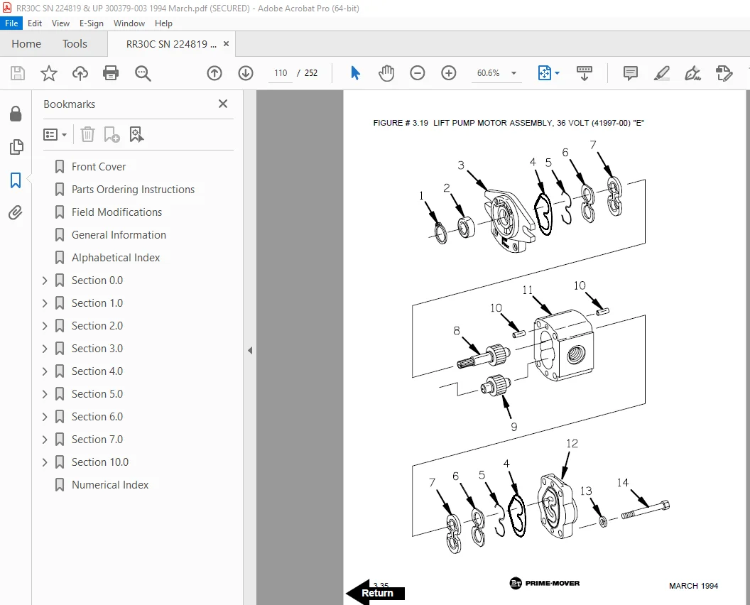
Figure # 3 19 Lift Pump Motor Assembly, 36 Volt 110
Figure # 3 20 Lift Control Valve Assembly 112
Figure # 3 21 Two Stage Cylinder and Reservoir Assembly 114
Figure # 3 22 Two Stage Cylinder Assembly 116
Figure # 3 23 Three Stage Cylinder and Reservoir Assembly 118
Figure # 3 24 Three Stage Staging Cylinder Assembly 120
Figure # 3 25 Three Stage Freelift Cylinder Assembly 122
Figure # 3 26 Hydraulic Schematic for 3 Function Control Handle 124
Figure # 3 27 Hydraulic Schematic Symbols 125
Figure # 3 28 Auxiliary Pump & Reservoir Assembly for 3 Function Control Handle 126
Figure # 3 29 Valve Assembly 128
Figure # 3 30 Two Stage Mast Hydraulic Assembly for 3 Function Control Handle 130
Figure # 3 31 Three Stage Mast Hydraulic Assembly for 3 Function Control Handle 132
Section 4 0 134
Figure # 4 1 Shielding Assembly 134
Figure # 4 2 Emergency Disconnect Assembly 136
Figure # 4 3 Auxiliary Control Assembly 138
Figure # 4 4 Hand Lift/Lower and Speed Control 140
Figure # 4 5 Forward Steering Control Assembly 142
Figure # 4 6 Rearward Steering Control Assembly 144
Figure # 4 7 Auxiliary Pump and Motor Installation 146
Figure # 4 8 Main Frame and Load Wheel Assembly 148
Figure # 4 9 Single Load Wheel Assembly 150
Figure # 4 9A Single Load Wheel Assembly 152
Figure # 4 10 5″ High Articulating Load Wheel Assembly 154
Figure # 4 10A 5″ High Articulating Load Wheel Assembly 156
Figure # 4 11 4″ High Articulating Load Wheel Assembly 158
Figure # 4 11A 4″ High Articulating Load Wheel Assembly 160
Figure # 4 12 Caster Assembly 162
Figure # 4 13 Hand Lift/Lower and Speed Control for 3 Function Control 164
Section 5 0 166
Figure # 5 1 Two Stage Mast Installation 166
Figure # 5 2 Two Stage Inner Column Assembly 168
Figure # 5 3 Two Stage Outer Column Assembly 170
Figure # 5 4 Two Stage Cylinder Assembly 172
Figure # 5 5 Two Stage Reach Assembly 174
Figure # 5 6 Two Stage Reach Front Frame 176
Figure # 5 7 Two Stage Sideshifter Assembly 178
Figure # 5 8 Two Stage Fork Assembly 180
Figure # 5 9 Three Stage Mast Installation 182
Figure # 5 10 Three Stage Inner Column Assembly 184
Figure # 5 11 Three Stage Freelift Cylinder Installation 186
Figure # 5 12 Three Stage Intermediate Column Assembly 188
Figure # 5 13 Three Stage Outer Column Assembly 190
Figure # 5 14 Three Stage Reach Assembly 192
Figure # 5 15 Three Stage Reach Front Frame 194
Figure # 5 16 Three Stage Sideshifter Assembly 196
Figure # 5 17 Three Stage Fork Assembly 198
Section 6 0 200
Figure # 6 1 Remote Lift/Lower EV-100 LX SCR Electrical Schematic 200
Figure # 6 2 Remote Lift/Lower EV-100 LX SCR Electrical Schematic Symbols 201
Figure # 6 3 Remote Lift/Lower Wiring Harness Assembly 202
Figure # 6 4 Remote Lift/Lower Three Stage Mast Cable Assembly 204
Figure # 6 5 Remote Lift/Lower Reach and Platform Cable Assembly 206
Figure # 6 6 Remote Lift/Lower Power Component Wiring 208
Figure # 6 7 Remote Lift/Lower Connector Assembly 210
Figure # 6 8 Remote Lift/Lower Hydraulic Schematic 212
Figure # 6 9 Remote Lift/Lower Manlift Hydraulic Schematic Symbols 213
Figure # 6 10 Remote Lift/Lower Hydraulic Diagram 214
Figure # 6 11 Blocking Remote Lift/Lower Valve Assembly 216
Figure # 6 12 Remote Lift/Lower Valve Assembly 218
Figure # 6 13 Remote Lift/Lower Load Backrest Installation 220
Figure # 6 14 Remote Lift/Lower Contactor Assembly 222
Section 7 0 224
Figure # 7 1 Battery Lift Interrupt “E” EV-100LX SCR Electrical Schematic 224
Figure # 7 2 Battery Lift Interrupt “E” EV-100LX SCR Electrical Schematic Symbols 225
Figure # 7 3 Battery Lift Interrupt “EE” EV-100LX SCR Electrical Schematic 226
Figure # 7 4 Battery Lift Interrupt “EE” EV-100LX SCR Electrical Schematic Symbols 227
Figure # 7 5 Battery Lift Interrupt Installation 228
Section 10 0 230
Figure # 10 1 Special Tools and Lubrications 230
Numerical Index 233
DESCRIPTION:
BT Prime Mover RR-30C Electric Reach Truck Parts Manual – PDF DOWNLOAD
Manual Part Number 300379-003
Effective Serial Number 224819
PARTS ORDERING INSTRUCTIONS:
HOW TO ORDER:
- When you order, supply the part number, quantity, model and serial numbers of your machine. Supplying this information will assure prompt, efficient handling of your order. The pictorial reference number is not needed and including it can only add confusion.
- Since your dealer carries many parts in stock and maintains up-to-date prices on all parts, he will be able to process your order immediately. If, for some reason, the part is not in stock, he will order it from the factory. In either event, he maintains a current file of service manuals, which give all available parts ordering or technical information.
- All prices are FOB factory in Muscatine, Iowa. Shipping charges are added to the price of the part shipping from the factory.
WHERE TO ORDER:
Always order parts from the dealer who sold you your BT PRIME-MOVER. If it is necessary for the dealer to order parts from the factory, he is able to get prompt service for you. Parts are shipped in accordance with shipping instructions given on the order.
S.V 10/01/2025