BT Prime Mover RR-30C Reach Truck Parts Manual – PDF DOWNLOAD
$35.95
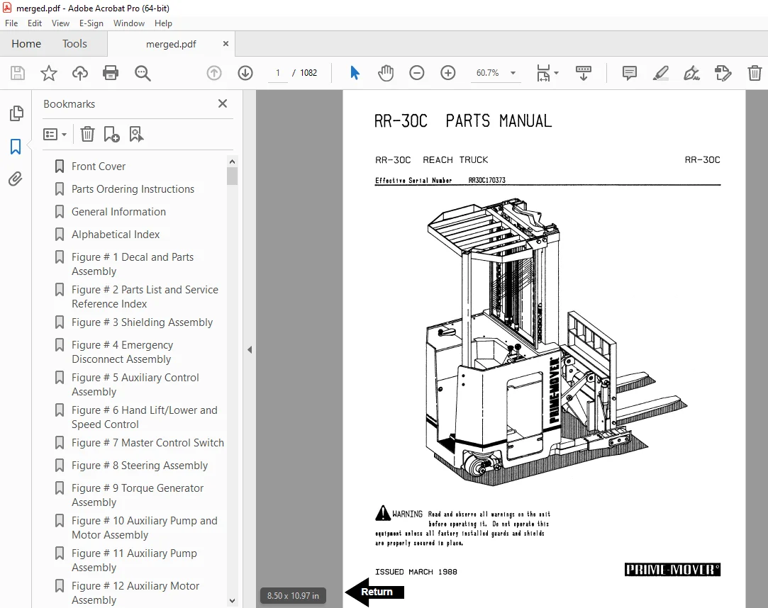
BT Prime Mover RR-30C Reach Truck Parts Manual – PDF DOWNLOAD
Effective Serial Number RR30C170373
Description
BT Prime Mover RR-30C Reach Truck Parts Manual – PDF DOWNLOAD
FILE DETAILS:
BT Prime Mover RR-30C Reach Truck Parts Manual – PDF DOWNLOAD
Language : English
Pages : 1082
Downloadable : Yes
File Type : PDF
IMAGES PREVIEW OF THE MANUAL:
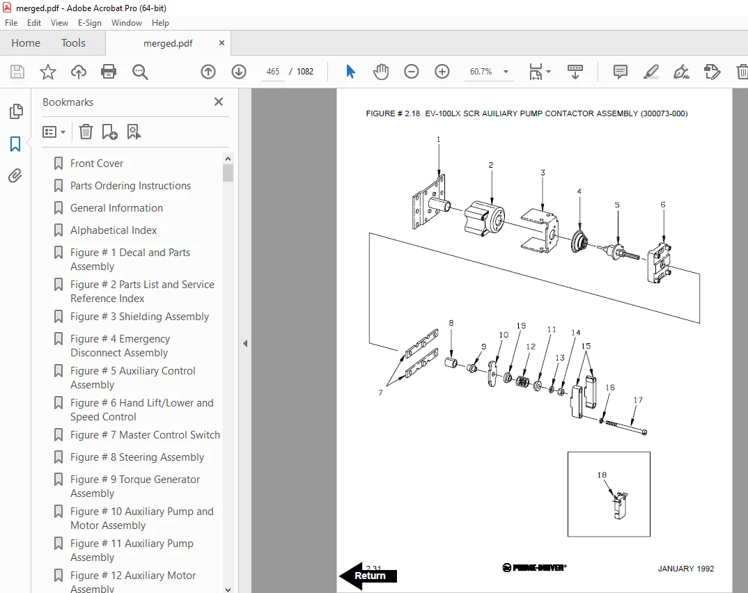
TABLE OF CONTENTS:
BT Prime Mover RR-30C Reach Truck Parts Manual – PDF DOWNLOAD
Effective Serial Number RR30C170373
Front Cover 1
Parts Ordering Instructions 2
General Information 3
Alphabetical Index 4
Figure # 1 Decal and Parts Assembly 6
Figure # 2 Parts List and Service Reference Index 8
Figure # 3 Shielding Assembly 10
Figure # 4 Emergency Disconnect Assembly 12
Figure # 5 Auxiliary Control Assembly 14
Figure # 6 Hand Lift/Lower and Speed Control 16
Figure # 7 Master Control Switch 18
Figure # 8 Steering Assembly 20
Figure # 9 Torque Generator Assembly 22
Figure # 10 Auxiliary Pump and Motor Assembly 24
Figure # 11 Auxiliary Pump Assembly 26
Figure # 12 Auxiliary Motor Assembly 28
Figure # 13 Transmission and Drive Motor Installation 30
Figure # 14 Brake Assembly 32
Figure # 15 Drive Motor Assembly 34
Figure # 16 Transmission Assembly Part # 1 36
Figure # 17 Transmission Assembly Part # 2 38
Figure # 18 EV-100 Electrical Schematic 40
Figure # 19 Electrical Schematic Symbols 41
Figure # 20 Wiring Assembly for Cold Storage 42
Figure # 21 Wiring Harness Assembly 44
Figure # 22 Limit Switch Wiring Harness Assembly 46
Figure # 23 Two Stage Mast Cable Assembly 48
Figure # 24 Three Stage Mast Cable Assembly 50
Figure # 25 Single Reach Cable Assembly 52
Figure # 26 Power Component Wiring 54
Figure # 27 EV-100 SCR Contactor Panel Assembly 56
Figure # 28 EV-100 SCR Control 58
Figure # 29 EV-100 Forward & Rearward Contactor Assembly 60
Figure # 30 EV-100 Lift Pump(s) and 1A Contactor Assembly 62
Figure # 31 EV-100 Steering Contactor Assembly 64
Figure # 32 Connector Assembly 66
Figure # 33 Warning Light Assembly 68
Figure # 34 Hydraulic Schematic 70
Figure # 35 Hydraulic Schematic Symbols 71
Figure # 36 Auxiliary Pump and Reservoir Assembly 72
Figure # 37 Auxiliary Control Valve Assembly 74
Figure # 38 Hydraulic Reservoir Assembly 76
Figure # 39 Two Stage Mast Hydraulic Assembly 78
Figure # 40 Three Stage Mast Hydraulic Assembly 80
Figure # 41 Single Reach, Reach Cylinder Hose Installation 82
Figure # 42 Single Reach Diverter Valve Assembly 84
Figure # 43 Single Reach, Reach Cylinder Assembly 86
Figure # 44 Single Reach, Tilt and Sideshift Hose Installation 88
Figure # 45 Tilt Cylinder Assembly 90
Figure # 46 Sideshifter Cylinder Assembly 92
Figure # 47 Lift Pump and Reservoir Assembly 94
Figure # 48 Lift Pump and Motor Assembly 96
Figure # 48 1 Lift Pump and Motor Assembly 98
Figure # 49 24 Volt Lift Pump Assembly 100
Figure # 50 36 Volt Lift Pump Assembly 102
Figure # 51 Lift Motor Assembly 104
Figure # 52 Lift Control Valve Assembly 106
Figure # 53 Two Stage Cylinder and Reservoir Assembly 108
Figure # 54 Two Stage Cylinder Assembly 110
Figure # 55 Three Stage Cylinder and Reservoir Assembly 112
Figure # 56 Three Stage Staging Cylinder Assembly 114
Figure # 57 Three Stage Freelift Cylinder Assembly 116
Figure # 58 Two Stage Mast Installation 118
Figure # 59 Two Stage Inner Column Assembly 120
Figure # 60 Two Stage Outer Column Assembly 122
Figure # 61 Two Stage Cylinder Installation 124
Figure # 62 Single Reach Assembly 126
Figure # 63 Single Reach with Tilt Front Frame 128
Figure # 64 Sideshifter Assembly 130
Figure # 65 Fork Assembly 132
Figure # 66 Three Stage Mast Installation 134
Figure # 67 Three Stage Outer Column Assembly 136
Figure # 68 Three Stage Intermediate Column Assembly 138
Figure # 69 Three Stage Inner Column Assembly 140
Figure # 70 Three Stage Freelift Cylinder Installation 142
Figure # 71 Main Frame and Load Wheel Assembly 144
Figure # 72 Single Load Wheel Assembly 146
Figure # 73 5″ High Articulating Load Wheel Assembly 148
Figure # 74 4″ High Articulating Load Wheel Assembly 150
Figure # 75 Caster Assembly 152
Figure # 76 Special Tools and Lubrications 154
Numerical Index 156
Appendix 1 for EV-1 SCR Electrical System 171
Figure # 1 EV-1 Electrical Schematic 172
Figure # 2 Electrical Schematic Symbols 173
Figure # 3 EV-1 Power Component Wiring 174
Figure # 4 EV-1 SCR and Contactor Panel Assembly 176
Figure # 5 EV-1 SCR Control 178
Figure # 6 EV-1 Transformer Assembly 180
Figure # 7 EV-1 Rectifier Heat Sink Assembly 182
Figure # 8 EV-1 Lift Pump and 1A Contactor Assembly 184
Figure # 9 EV-1 Steering Contactor Assembly 186
Figure # 10 EV-1 Forward and Rearward Contactor Assembly 188
Front Cover 190
Parts Ordering Instructions 191
General Information 192
Alphabetical Index 193
Figure # 0 1 Decals and Parts Assembly 197
Figure # 0 2 Parts List Index 199
Figure # 1 1 Transmission and Drive Motor Installation 203
Figure # 1 2 Drive Motor and Brake Assembly 205
Figure # 1 3 Transmission Assembly 207
Figure # 1 4 Transmission Assembly 209
Figure # 2 1 “E” EV-100LX SCR Electrical Schematic 211
Figure # 2 2 EV-100LX SCR Electrical Schematic Symbols 212
Figure # 2 3 “EE” EV-100LX SCR Electrical Schematic 213
Figure # 2 4 “EE” EV-100LX SCR Electrical Schematic Symbols 214
Figure # 2 5 Wiring Assembly for Cold Storage 215
Figure # 2 6 Wiring Harness Assembly 217
Figure # 2 7 Limit Switch Wiring Assembly 219
Figure # 2 8 Two Stage Mast Cable Assembly 221
Figure # 2 9 Three Stage Mast Cable Assembly 223
Figure # 2 10 Reach Cable Assembly 225
Figure # 2 11 EV-100LX Power Component Wiring 227
Figure # 2 12 EV-100LX TX and TT SCR Control Panel Assembly 229
Figure # 2 13 EV-100LX Contactor Panel Assembly & Related Parts for “E” and “EE” 231
Figure # 2 14 EV-100LX Contactor Panel Assembly 233
Figure # 2 15 EV-100LX SCR Forward & Rearward Contactor Assembly 235
Figure # 2 16 EV-100LX SCR 1A Contactor Assembly 237
Figure # 2 17 Lift Pump Contactor Assembly 239
Figure # 2 18 EV-100LX SCR Auxiliary Pump Contactor Assembly 241
Figure # 2 19 Power Connector Assembly 243
Figure # 2 20 Lift Pump Motor Assembly 245
Figure # 2 21 Drive Motor Assembly 247
Figure # 2 22 Auxiliary Pump Motor Assembly 249
Figure # 2 23 Warning Light Assembly 251
Figure # 2 24 “E” EV-100LX TT SCR Electrical Schematic 253
Figure # 2 25 “E” EV-100LX TT SCR Electrical Schematic Symbols 254
Figure # 2 26 “EE” EV-100LX TT SCR Electrical Schematic 255
Figure # 2 27 “EE” EV-100LX TT SCR Electrical Schematic Symbols 256
Figure # 2 28 EV-100LX Dash Display Installation 257
Figure # 3 1 Hydraulic Schematic 259
Figure # 3 2 Hydraulic Schematic Symbols 260
Figure # 3 3 Auxiliary Pump and Reservoir Assembly 261
Figure # 3 4 Auxiliary Control Valve Assembly 263
Figure # 3 5 Auxiliary Pump and Motor Assembly 265
Figure # 3 6 Auxiliary Pump Assembly 267
Figure # 3 7 Hydraulic Reservoir Assembly 269
Figure # 3 8 Torque Generator Assembly 271
Figure # 3 9 Two Stage Mast Hydraulic Assembly 273
Figure # 3 10 Three Stage Mast Hydraulic Assembly 275
Figure # 3 11 Reach Cylinder Hose Installation 277
Figure # 3 12 Reach Diverter Valve Assembly 279
Figure # 3 13 Reach Cylinder Assembly 281
Figure # 3 14 Tilt and Sideshift Hose Installation 283
Figure # 3 15 Tilt Cylinder Assembly 285
Figure # 3 16 Lift Pump and Reservoir Assembly 287
Figure # 3 17 Lift Pump Motor Assembly 289
Figure # 3 18 Lift Pump Motor Assembly, 24 Volt 291
Figure # 3 19 Lift Pump Motor Assembly, 36 Volt 293
Figure # 3 20 Lift Control Valve Assembly 295
Figure # 3 21 Two Stage Cylinder and Reservoir Assembly 297
Figure # 3 22 Two Stage Cylinder Assembly 299
Figure # 3 24 Three Stage Staging Cylinder Assembly 303
Figure # 3 25 Three Stage Freelift Cylinder Assembly 305
Figure # 4 1 Shielding Assembly 307
Figure # 4 2 Emergency Disconnect Assembly 309
Figure # 4 3 Auxiliary Control Assembly 311
Figure # 4 4 Hand Lift/Lower and Speed Control 313
Figure # 4 5 Forward Steering Control Assembly 315
Figure # 4 6 Rearward Steering Control Assembly 317
Figure # 4 7 Auxiliary Pump and Motor Installation 319
Figure # 4 8 Main Frame and Load Wheel Assembly 321
Figure # 4 9 Single Load Wheel Assembly 323
Figure # 4 10 5″ High Articulating Load Wheel Assembly 325
Figure # 4 11 4″ High Articulating Load Wheel Assembly 327
Figure # 4 12 Caster Assembly 329
Figure # 5 1 Two Stage Mast Installation 331
Figure # 5 2 Two Stage Inner Column Assembly 333
Figure # 5 3 Two Stage Outer Column Assembly 335
Figure # 5 4 Two Stage Cylinder Assembly 337
Figure # 5 5 Two Stage Reach Assembly 339
Figure # 5 6 Two Stage Reach Front Frame 341
Figure # 5 7 Two Stage Sideshifter Assembly 343
Figure # 5 8 Two Stage Fork Assembly 345
Figure # 5 9 Three Stage Mast Installation 347
Figure # 5 10 Three Stage Inner Column Assembly 349
Figure # 5 11 Three Stage Freelift Cylinder Installation 351
Figure # 5 12 Three Stage Intermediate Column Assembly 353
Figure # 5 13 Three Stage Outer Column Assembly 355
Figure # 5 14 Three Stage Reach Assembly 357
Figure # 5 15 Three Stage Reach Front Frame 359
Figure # 5 16 Three Stage Sideshifter Assembly 361
Figure # 5 17 Three Stage Fork Assembly 363
Figure # 6 1 Manlift EV-100 LX SCR Electrical Schematic 365
Figure # 6 2 Manlift EV-100 LX SCR Electrical Schematic Symbols 366
Figure # 6 3 Three Stage Fork Assembly 367
Figure # 6 4 Manlift Three Stage Mast Cable Assembly 369
Figure # 6 5 Manlift Reach and Platform Cable Assembly 371
Figure # 6 6 Manlift Power Component Wiring 373
Figure # 6 7 Manlift Connector Assembly 375
Figure # 6 8 Manlift Hydraulic Schematic 377
Figure # 6 9 Manlift Hydraulic Schematic Symbols 378
Figure # 6 10 Manlift Hydraulic Diagram 379
Figure # 6 11 Block Manlift Valve Assembly 381
Figure # 6 12 Manlift Valve Assembly 383
Figure # 6 13 Manlift Load Backrest Installation 385
Figure # 7 1 Battery Lift Interrupt “E” EV-100LX SCR Electrical Schematic 387
Figure # 7 2 Battery Lift Interrupt “E” EV-100LX SCR Electrical Schematic Symbols 388
Figure # 7 3 Battery Lift Interrupt “EE” EV-100LX SCR Electrical Schematic 389
Figure # 7 4 Battery Lift Interrupt “EE” EV-100LX SCR Electrical Schematic Symbols 390
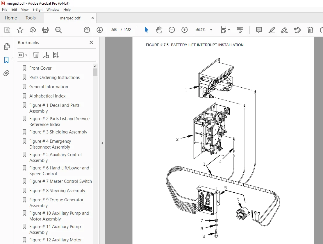
Figure # 7 5 Battery Lift Interrupt Installation 391
Figure # 10 1 Special Tools and Lubrications 393
Numerical Index 396
Front Cover 414
Parts Ordering Instructions 415
General Information 416
Alphabetical Index 417
Figure # 0 1 Decals and Parts Assembly 421
Figure # 0 2 Parts List Index 423
Figure # 1 1 Transmission and Drive Motor Installation 427
Figure # 1 2 Drive Motor and Brake Assembly 429
Figure # 1 3 Transmission Assembly 431
Figure # 1 4 Transmission Assembly 433
Figure # 2 1 “E” EV-100LX SCR Electrical Schematic 435
Figure # 2 2 “E” EV-100LX SCR Electrical Schematic Symbols 436
Figure # 2 3 “EE” EV-100LX SCR Electrical Schematic 437
Figure # 2 4 “EE” EV-100LX SCR Electrical Schematic Symbols 438
Figure # 2 5 Wiring Assembly for Cold Storage 439
Figure # 2 6 Wiring Harness Assembly 441
Figure # 2 7 Limit Switch Wiring Assembly 443
Figure # 2 8 Two Stage Mast Cable Assembly 445
Figure # 2 9 Three Stage Mast Cable Assembly 447
Figure # 2 10 Reach Cable Assembly 449
Figure # 2 11 EV-100LX Power Component Wiring 451
Figure # 2 12 EV-100LX TX & TT SCR Control Panel Assembly 453
Figure # 2 13 EV-100LX Contactor Panel Assembly & Related Parts for “E” and “EE” 455
Figure # 2 14 EV-100LX Contactor Panel Assembly 457
Figure # 2 15 EV-100LX SCR Forward & Rearward Contactor Assembly 459
Figure # 2 16 EV-100LX SCR 1A Contactor Assembly 461
Figure # 2 17 Lift Pump Contactor Assembly 463
Figure # 2 18 EV-100LX SCR Auxiliary Pump Contactor Assembly 465
Figure # 2 19 Power Connector Assembly 467
Figure # 2 20 Lift Pump Motor Assembly, 24 & 36 Volt 469
Figure # 2 21 Drive Motor Assembly, 24 & 36 Volt 471
Figure # 2 22 Auxiliary Pump Motor Assembly 473
Figure # 2 23 Warning Light Assembly 475
Figure # 2 24 “E” EV-100LX TT SCR Electrical Schematic 477
Figure # 2 25 “E” EV-100LX TT SCR Electrical Schematic Symbols 478
Figure # 2 26 “EE” EV-100LX TT SCR Electrical Schematic 479
Figure # 2 27 “EE” EV-100LX TT SCR Electrical Schematic Symbols 480
Figure # 2 28 EV-100LX Dash Display Installation 481
Figure # 3 1 Hydraulic Schematic 483
Figure # 3 2 Hydraulic Schematic Symbols 484
Figure # 3 3 Auxiliary Pump and Reservoir Assembly 485
Figure # 3 4 Auxiliary Control Valve Assembly 487
Figure # 3 5 Auxiliary Pump and Motor Assembly 489
Figure # 3 6 Auxiliary Pump Assembly 491
Figure # 3 7 Hydraulic Reservoir Assembly 493
Figure # 3 8 Torque Generator Assembly 495
Figure # 3 9 Two Stage Mast Hydraulic Assembly 497
Figure # 3 10 Three Stage Mast Hydraulic Assembly 499
Figure # 3 11 Reach Cylinder Hose Installation 501
Figure # 3 12 Reach Diverter Valve Assembly 503
Figure # 3 13 Reach Cylinder Assembly 505
Figure # 3 14 Tilt and Sideshift Hose Installation 507
Figure # 3 15 Tilt Cylinder Assembly 509
Figure # 3 16 Lift Pump and Reservoir Assembly 511
Figure # 3 17 Lift Pump Motor Assembly 513
Figure # 3 18 Lift Pump Motor Assembly, 24 Volt 515
Figure # 3 19 Lift Pump Motor Assembly, 36 Volt 517
Figure # 3 20 Lift Control Valve Assembly 519
Figure # 3 21 Two Stage Cylinder and Reservoir Assembly 521
Figure # 3 22 Two Stage Cylinder Assembly 523
Figure # 3 23 Three Stage Cylinder and Reservoir Assembly 525
Figure # 3 24 Three Stage Staging Cylinder Assembly 527
Figure # 3 25 Three Stage Freelift Cylinder Assembly 529
Figure # 4 1 Shielding Assembly 531
Figure # 4 2 Emergency Disconnect Assembly 533
Figure # 4 3 Auxiliary Control Assembly 535
Figure # 4 4 Hand Lift/Lower and Speed Control 537
Figure # 4 5 Forward Steering Control Assembly 539
Figure # 4 6 Rearward Steering Control Assembly 541
Figure # 4 7 Auxiliary Pump and Motor Installation 543
Figure # 4 8 Main Frame and Load Wheel Assembly 545
Figure # 4 9 Single Load Wheel Assembly 547
Figure # 4 10 5″ High Articulating Load Wheel Assembly 549
Figure # 4 11 4″ High Articulating Load Wheel Assembly 551
Figure # 4 12 Caster Assembly 553
Figure # 4 13 Hand Lift/Lower and Speed Control for 3 Function Control 555
Figure # 5 1 Two Stage Mast Installation 557
Figure # 5 2 Two Stage Inner Column Assembly 559
Figure # 5 3 Two Stage Outer Column Assembly 561
Figure # 5 4 Two Stage Cylinder Assembly 563
Figure # 5 5 Two Stage Reach Assembly 565
Figure # 5 6 Two Stage Reach Front Frame 567
Figure # 5 7 Two Stage Sideshifter Assembly 569
Figure # 5 8 Two Stage Fork Assembly 571
Figure # 5 9 Three Stage Mast Installation 573
Figure # 5 10 Three Stage Inner Column Assembly 575
Figure # 5 11 Three Stage Freelift Cylinder Installation 577
Figure # 5 12 Three Stage Intermediate Column Assembly 579
Figure # 5 13 Three Stage Outer Column Assembly 581
Figure # 5 14 Three Stage Reach Assembly 583
Figure # 5 15 Three Stage Reach Front Frame 585
Figure # 5 16 Three Stage Sideshifter Assembly 587
Figure # 5 17 Three Stage Fork Assembly 589
Figure # 6 1 Manlift EV-100 LX SCR Electrical Schematic 591
Figure # 6 2 Manlift EV-100 LX SCR Electrical Schematic Symbols 592
Figure # 6 3 Three Stage Fork Assembly 593
Figure # 6 4 Manlift Three Stage Mast Cable Assembly 595
Figure # 6 5 Manlift Reach and Platform Cable Assembly 597
Figure # 6 6 Manlift Power Component Wiring 599
Figure # 6 7 Manlift Connector Assembly 601
Figure # 6 8 Manlift Hydraulic Schematic 603
Figure # 6 9 Manlift Hydraulic Schematic Symbols 604
Figure # 6 10 Manlift Hydraulic Diagram 605
Figure # 6 11 Block Manlift Valve Assembly, 24 & 36 Volt 607
Figure # 6 12 Manlift Valve Assembly, 24 & 36 Volt 609
Figure # 6 13 Manlift Load Backrest Installation 611
Figure # 7 1 Battery Lift Interrupt “E” EV-100LX SCR Electrical Schematic 613
Figure # 7 2 Battery Lift Interrupt “E” EV-100LX SCR Electrical Schematic Symbols 614
Figure # 7 3 Battery Lift Interrupt “EE” EV-100LX SCR Electrical Schematic 615
Figure # 7 4 Battery Lift Interrupt “EE” EV-100LX SCR Electrical Schematic Symbols 616
Figure # 7 5 Battery Lift Interrupt Installation 617
Figure # 10 1 Special Tools and Lubrications 619
Numerical Index 622
Front Cover 639
Parts Ordering Instructions 640
Field Modifications 640
General Information 641
Alphabetical Index 642
Section 0 0 646
Figure # 0 1 Decals and Parts Assembly 646
Section 1 0 648
Figure # 1 1 Transmission and Drive Motor Installation 648
Figure # 1 2 Drive Motor and Brake Assembly 650
Figure # 1 3 Transmission Assembly Part #1 652
Figure # 1 4 Transmission Assembly Part #2 654
Section 2 0 656
Figure # 2 1 “E” EV-100LX SCR Electrical Schematic 656
Figure # 2 2 “E” EV-100LX SCR Electrical Schematic Symbols 657
Figure # 2 3 “EE” EV-100LX SCR Electrical Schematic 658
Figure # 2 4 “EE” EV-100LX SCR Electrical Schematic Symbols 659
Figure # 2 5 Wiring Assembly for Cold Storage 660
Figure # 2 6 Wiring Harness Assembly 662
Figure # 2 7 Limit Switch Wiring Assembly 664
Figure # 2 8 Two Stage Mast Cable Assembly 666
Figure # 2 9 Three Stage Mast Cable Assembly 668
Figure # 2 10 Reach Cable Assembly 670
Figure # 2 11 EV-100LX Power Component Wiring 672
Figure # 2 12 EV-100LX TX & TT SCR Control Panel Assembly 674
Figure # 2 13 EV-100LX Contactor Panel Assembly & Related Parts for “E” and “EE” 676
Figure # 2 14 EV-100LX Contactor Panel Assembly 678
Figure # 2 15 EV-100LX SCR Forward & Rearward Contactor Assembly 680
Figure # 2 16 EV-100LX SCR 1A Contactor Assembly 682
Figure # 2 17 Lift Pump Contactor Assembly 684
Figure # 2 18 EV-100LX SCR Auxiliary Pump Contactor Assembly 686
Figure # 2 19 Power Connector Assembly 688
Figure # 2 20 Lift Pump Motor Assembly 690
Figure # 2 21 Lift Pump Motor Assembly, 36 Volt 692
Figure # 2 22 Drive Motor Assembly 694
Figure # 2 23 Auxiliary Pump Motor Assembly 696
Figure # 2 24 Warning Light Assembly 698
Figure # 2 25 “E” EV-100LX TT SCR Electrical Schematic 700
Figure # 2 26 “E” EV-100LX TT SCR Electrical Schematic Symbols 701
Figure # 2 27 “EE” EV-100LX TT SCR Electrical Schematic 702
Figure # 2 28 “EE” EV-100LX TT SCR Electrical Schematic Symbols 703
Figure # 2 29 EV-100LX Dash Display Installation 704
Figure # 2 30 EV-100LX SCR Electrical Schematic – 3 Function Control Handle 706
Figure # 2 31 EV-100LX SCR Electrical Schematic Symbols 707
Figure # 2 30A TX EV-100LX Electrical Schematic – 3 Function Control Handle 708
Figure # 2 31A EV-100LX SCR Electrical Schematic Symbols 709
Figure # 2 30B TT EV-100LX Electrical Schematic – 3 Function Control Handle 710
Figure # 2 31B EV-100LX SCR Electrical Schematic Symbols 711
Figure # 2 32 Wiring Harness Assembly for 3 Function Control Valve 712
Section 3 0 714
Figure # 3 1 Hydraulic Schematic 714
Figure # 3 2 Hydraulic Schematic Symbols 715
Figure # 3 3 Auxiliary Pump and Reservoir Assembly 716
Figure # 3 4 Auxiliary Control Valve Assembly 718
Figure # 3 5 Auxiliary Pump and Motor Assembly 720
Figure # 3 6 Auxiliary Pump Assembly 722
Figure # 3 7 Hydraulic Reservoir Assembly 724
Figure # 3 8 Torque Generator Assembly 726
Figure # 3 9 Two Stage Mast Hydraulic Assembly 728
Figure # 3 10 Three Stage Mast Hydraulic Assembly 730
Figure # 3 11 Reach Cylinder Hose Installation 732
Figure # 3 12 Reach Diverter Valve Assembly 734
Figure # 3 13 Reach Cylinder Assembly 736
Figure # 3 14 Tilt and Sideshift Hose Installation 738
Figure # 3 15 Tilt Cylinder Assembly 740
Figure # 3 16 Lift Pump and Reservoir Assembly 742
Figure # 3 17 Lift Pump Motor Assembly 744
Figure # 3 18 Lift Pump Assembly 746
Figure # 3 19 Lift Pump Motor Assembly, 36 Volt 748
Figure # 3 20 Lift Control Valve Assembly 750
Figure # 3 21 Two Stage Cylinder and Reservoir Assembly 752
Figure # 3 22 Two Stage Cylinder Assembly 754
Figure # 3 23 Three Stage Cylinder and Reservoir Assembly 756
Figure # 3 24 Three Stage Staging Cylinder Assembly 758
Figure # 3 25 Three Stage Freelift Cylinder Assembly 760
Figure # 3 26 Hydraulic Schematic for 3 Function Control Handle 762
Figure # 3 27 Hydraulic Schematic Symbols 763
Figure # 3 28 Auxiliary Pump & Reservoir Assembly for 3 Function Control Handle 764
Figure # 3 29 Valve Assembly 766
Figure # 3 30 Two Stage Mast Hydraulic Assembly for 3 Function Control Handle 768
Figure # 3 31 Three Stage Mast Hydraulic Assembly for 3 Function Control Handle 770
Section 4 0 772
Figure # 4 1 Shielding Assembly 772
Figure # 4 2 Emergency Disconnect Assembly 774
Figure # 4 3 Auxiliary Control Assembly 776
Figure # 4 4 Hand Lift/Lower and Speed Control 778
Figure # 4 5 Forward Steering Control Assembly 780
Figure # 4 6 Rearward Steering Control Assembly 782
Figure # 4 7 Auxiliary Pump and Motor Installation 784
Figure # 4 8 Main Frame and Load Wheel Assembly 786
Figure # 4 9 Single Load Wheel Assembly 788
Figure # 4 9A Single Load Wheel Assembly 790
Figure # 4 10 5″ High Articulating Load Wheel Assembly 792
Figure # 4 10A 5″ High Articulating Load Wheel Assembly 794
Figure # 4 11 4″ High Articulating Load Wheel Assembly 796
Figure # 4 11A 4″ High Articulating Load Wheel Assembly 798
Figure # 4 12 Caster Assembly 800
Figure # 4 13 Hand Lift/Lower and Speed Control for 3 Function Control 802
Section 5 0 804
Figure # 5 1 Two Stage Mast Installation 804
Figure # 5 2 Two Stage Inner Column Assembly 806
Figure # 5 3 Two Stage Outer Column Assembly 808
Figure # 5 4 Two Stage Cylinder Assembly 810
Figure # 5 5 Two Stage Reach Assembly 812
Figure # 5 6 Two Stage Reach Front Frame 814
Figure # 5 7 Two Stage Sideshifter Assembly 816
Figure # 5 8 Two Stage Fork Assembly 818
Figure # 5 9 Three Stage Mast Installation 820
Figure # 5 10 Three Stage Inner Column Assembly 822
Figure # 5 11 Three Stage Freelift Cylinder Installation 824
Figure # 5 12 Three Stage Intermediate Column Assembly 826
Figure # 5 13 Three Stage Outer Column Assembly 828
Figure # 5 14 Three Stage Reach Assembly 830
Figure # 5 15 Three Stage Reach Front Frame 832
Figure # 5 16 Three Stage Sideshifter Assembly 834
Figure # 5 17 Three Stage Fork Assembly 836
Section 6 0 838
Figure # 6 1 Remote Lift/Lower EV-100 LX SCR Electrical Schematic 838
Figure # 6 2 Remote Lift/Lower EV-100 LX SCR Electrical Schematic Symbols 839
Figure # 6 3 Remote Lift/Lower Wiring Harness Assembly 840
Figure # 6 4 Remote Lift/Lower Three Stage Mast Cable Assembly 842
Figure # 6 5 Remote Lift/Lower Reach and Platform Cable Assembly 844
Figure # 6 6 Remote Lift/Lower Power Component Wiring 846
Figure # 6 7 Remote Lift/Lower Connector Assembly 848
Figure # 6 8 Remote Lift/Lower Hydraulic Schematic 850
Figure # 6 9 Remote Lift/Lower Manlift Hydraulic Schematic Symbols 851
Figure # 6 10 Remote Lift/Lower Hydraulic Diagram 852
Figure # 6 11 Blocking Remote Lift/Lower Valve Assembly 854
Figure # 6 12 Remote Lift/Lower Valve Assembly 856
Figure # 6 13 Remote Lift/Lower Load Backrest Installation 858
Figure # 6 14 Remote Lift/Lower Contactor Assembly 860
Section 7 0 862
Figure # 7 1 Battery Lift Interrupt “E” EV-100LX SCR Electrical Schematic 862
Figure # 7 2 Battery Lift Interrupt “E” EV-100LX SCR Electrical Schematic Symbols 863
Figure # 7 3 Battery Lift Interrupt “EE” EV-100LX SCR Electrical Schematic 864
Figure # 7 4 Battery Lift Interrupt “EE” EV-100LX SCR Electrical Schematic Symbols 865
Figure # 7 5 Battery Lift Interrupt Installation 866
Section 10 0 868
Figure # 10 1 Special Tools and Lubrications 868
Numerical Index 871
Front Cover 891
Parts Ordering Instructions 892
General Information 893
Alphabetical Index 894
Section 0 0 898
Figure # 0 1 Decals and Parts Assembly 898
Section 1 0 900
Figure # 1 1 Transmission and Drive Motor Installation 900
Figure # 1 2 Drive Motor and Brake Assembly 902
Figure # 1 3 Transmission Assembly Part # I 904
Figure # 1 4 Transmission Assembly Part # II 906
Section 2 0 908
Figure # 2 1 TX Electrical Schematic – Multi-Function Control 908
Figure # 2 2 Electrical Schematic Symbols 909
Figure # 2 3 TT Electrical Schematic – Multi-Function Control 910
Figure # 2 4 Electrical Schematic Symbols 911
Figure # 2 5 Wiring Assembly for Cold Storage 912
Figure # 2 6 Lift Control Wiring Harness – Multi-Function Control 914
Figure # 2 7 Limit Switch Wiring Assembly 916
Figure # 2 8 Two Stage Mast Cable Assembly 918
Figure # 2 9 Three Stage Mast Cable Assembly 920
Figure # 2 10 Reach Cable Assembly 922
Figure # 2 11 Power Component Wiring 924
Figure # 2 12 SCR Control Panel 926
Figure # 2 13 Contactor Panel Assembly & Related Parts for “E” and “EE” 928
Figure # 2 14 Contactor Panel Assembly 930
Figure # 2 15 Forward & Rearward Contactor Assembly 932
Figure # 2 16 Contactor Assembly 934
Figure # 2 17 Power Connector Assembly 936
Figure # 2 18 Lift Pump Motor Assembly 938
Figure # 2 19 Drive Motor Assembly 940
Figure # 2 20 Auxiliary Pump Motor Assembly 942
Figure # 2 21 Warning Light and Work Light Assembly 944
Figure # 2 22 EV-100LX Dash Display Installation 946
Figure # 2 23 “E” Electrical Schematic – Single Function Control 948
Figure # 2 24 Electrical Schematic Symbols 949
Figure # 2 25 “EE” Electrical Schematic – Single Function Control 950
Figure # 2 26 Electrical Schematic Symbols 951
Figure # 2 27 Lift Control Wiring Harness – Single Function Control 952
Figure # 2 28 Battery Lift Interrupt Installation 954
Section 3 0 956
Figure # 3 1 Hydraulic Schematic 956
Figure # 3 2 Hydraulic Schematic Symbols 957
Figure # 3 3 Auxiliary Pump & Reservoir Assembly 958
Figure # 3 4 Auxiliary Control Valve & Related Parts 960
Figure # 3 5 Two Stage Mast Hydraulic Assembly 962
Figure # 3 6 Three Stage Mast Hydraulic Assembly 964
Figure # 3 7 Reach Cylinder Hose Installation 966
Figure # 3 8 Tilt and Sideshift Hose Installation 968
Figure # 3 9 Lift Pump and Reservoir Assembly 970
Figure # 3 10 Two Stage Cylinder and Reservoir Assembly 972
Figure # 3 11 Two Stage Cylinder Assembly 974
Figure # 3 12 Three Stage Cylinder & Reservoir Assembly – RR-30 976
Figure # 3 13 Three Stage Cylinder & Reservoir Assembly – RR-34 978
Figure # 3 14 Three Stage Staging Cylinder Assembly 980
Figure # 3 15 Three Stage Freelift Cylinder Assembly 982
Figure # 3 16 Hydraulic Reservoir Assembly 984
Figure # 3 17 Auxiliary Control Valve Assembly – Single Function Control 986
Figure # 3 18 Lift Control Valve Assembly 988
Figure # 3 19 Valve Assembly – Multi-Function Control 990
Figure # 3 20 Reach Diverter Valve Assembly 992
Figure # 3 21 Torque Generator Assembly 994
Figure # 3 22 Lift Pump & Motor Assembly 996
Figure # 3 23 Lift Pump Assembly 998
Figure # 3 24 Lift Pump Assembly, 36 Volt “E” 1000
Figure # 3 25 Auxiliary Pump and Motor Assembly 1002
Figure # 3 26 Auxiliary Pump Assembly 1004
Figure # 3 27 Reach Cylinder Assembly 1006
Figure # 3 28 Tilt Cylinder Assembly 1008
Section 4 0 1010
Figure # 4 1 Shielding Assembly 1010
Figure # 4 2 Emergency Disconnect Assembly 1012
Figure # 4 3 Auxiliary Control Assembly – Single Function Control 1014
Figure # 4 4 Hand Lift/Lower and Speed Control – Multi-Function Control 1016
Figure # 4 5 Hand Lift/Lower and Speed Control – Single Function Control 1018
Figure # 4 6 Forward Steering Control Assembly 1020
Figure # 4 7 Rearward Steering Control Assembly 1022
Figure # 4 8 Auxiliary Pump and Motor Installation 1024
Figure # 4 9 Main Frame and Load Wheel Assembly 1026
Figure # 4 10 5″ High Articulating Load Wheel Assembly 1028
Figure # 4 11 Single Load Wheel Assembly 1030
Figure # 4 12 4″ High Articulating Load Wheel Assembly 1032
Figure # 4 13 Caster Assembly 1034
Section 5 0 1036
Figure # 5 1 Two Stage Mast Installation 1036
Figure # 5 2 Two Stage Inner Column Assembly 1038
Figure # 5 3 Two Stage Outer Column Assembly 1040
Figure # 5 4 Two Stage Cylinder Installation 1042
Figure # 5 5 Three Stage Mast Installation 1044
Figure # 5 6 Three Stage Inner Column Assembly 1046
Figure # 5 7 Three Stage Freelift Cylinder Installation 1048
Figure # 5 8 Three Stage Intermediate Column Assembly 1050
Figure # 5 9 Three Stage Outer Column Assembly 1052
Figure # 5 10 Reach Assembly 1054
Figure # 5 11 Reach Front Frame Assembly 1056
Figure # 5 12 Sideshifter Assembly 1058
Figure # 5 13 Fork Assembly 1060
Section 10 0 1062
Figure # 10 1 Special Tools and Lubrications 1062
Numerical Index 1065
S.V 20/01/2025