BT Prime-Mover RR-34B Reach Truck Parts Manual – PDF DOWNLOAD
$34.95
BT Prime-Mover RR-34B Reach Truck Parts Manual – PDF DOWNLOAD
Effective Serial Number RR34B181728
Description
BT Prime-Mover RR-34B Reach Truck Parts Manual – PDF DOWNLOAD
FILE DETAILS:
BT Prime-Mover RR-34B Reach Truck Parts Manual – PDF DOWNLOAD
Language : English
Pages : 928
Downloadable : Yes
File Type : PDF
IMAGES PREVIEW OF THE MANUAL:
TABLE OF CONTENTS:
BT Prime-Mover RR-34B Reach Truck Parts Manual – PDF DOWNLOAD
Effective Serial Number RR34B181728
Front Cover 1
Parts Ordering Instructions 2
Field Modifications 2
General Information 3
Alphabetical Index 4
Figure # 1 Decal and Parts Assembly 6
Figure # 2 Parts List and Service Reference Index 8
Figure # 3 Shielding Assembly 10
Figure # 4 Emergency Disconnect Assembly 12
Figure # 5 Auxiliary Control Assembly 14
Figure # 6 Hand Lift/Lower and Speed Control 16
Figure # 7 Master Control Switch 18
Figure # 8 Steering Assembly 20
Figure # 9 Torque Generator Assembly 22
Figure # 10 Auxiliary Pump and Motor Assembly 24
Figure # 11 Auxiliary Pump Assembly 26
Figure # 12 Auxiliary Motor Assembly 28
Figure # 13 Transmission and Drive Motor Installation 30
Figure # 14 Brake Assembly 32
Figure # 15 Drive Motor Assembly 34
Figure # 16 Transmission Assembly Part # 1 36
Figure # 17 Transmission Assembly Part # 2 38
Figure # 18 EV-100 Electrical Schematic 40
Figure # 19 Electrical Schematic Symbols 41
Figure # 20 Wiring Assembly for Cold Storage 42
Figure # 21 Wiring Harness Assembly 44
Figure # 22 Limit Switch Wiring Harness Assembly 46
Figure # 23 Two Stage Mast Cable Assembly 48
Figure # 24 Three Stage Mast Cable Assembly 50
Figure # 25 Single Reach Cable Assembly 52
Figure # 26 Double Reach Cable Assembly 54
Figure # 27 Power Component Wiring 56
Figure # 28 EV-100 SCR Contactor Panel Assembly 58
Figure # 29 EV-100 SCR Control 60
Figure # 30 EV-100 Forward & Rearward Contactor Assembly 62
Figure # 31 EV-100 Lift Pump and 1A Contactor Assembly 64
Figure # 32 EV-100 Steering Contactor Assembly 66
Figure # 33 Connector Assembly 68
Figure # 34 Warning Light Assembly 70
Figure # 35 Hydraulic Schematic 72
Figure # 36 Hydraulic Schematic Symbols 73
Figure # 37 Auxiliary Pump and Reservoir Assembly 74
Figure # 38 Auxiliary Control Valve Assembly 76
Figure # 39 Hydraulic Reservoir Assembly 78
Figure # 40 Two Stage Mast Hydraulic Assembly 80
Figure # 41 Three Stage Mast Hydraulic Assembly 82
Figure # 42 Single Reach, Reach Cylinder Hose Installation 84
Figure # 43 Single Reach Diverter Valve Assembly 86
Figure # 44 Single Reach, Reach Cylinder Assembly 88
Figure # 45 Single Reach, Tilt and Sideshift Hose Installation 90
Figure # 46 Tilt Cylinder Assembly 92
Figure # 47 Sideshifter Cylinder Assembly 94
Figure # 48 Double Reach with Tilt and Sideshifter 96
Figure # 49 Double Reach Diverter Valve Assembly 98
Figure # 50 Double Reach, Reach Cylinder Assembly 100
Figure # 51 Lift Pump and Reservoir Assembly 102
Figure # 52 Lift Pump and Motor Assembly 104
Figure # 52 1 Lift Pump and Motor Assembly 106
Figure # 53 24 Volt Lift Pump Assembly 108
Figure # 54 36 Volt Lift Pump Assembly 110
Figure # 55 Lift Motor Assembly 112
Figure # 56 Lift Control Valve Assembly 114
Figure # 57 Two Stage Cylinder and Reservoir Assembly 116
Figure # 58 Two Stage Cylinder Assembly 118
Figure # 59 Three Stage Cylinder and Reservoir Assembly 120
Figure # 60 Three Stage Staging Cylinder Assembly 122
Figure # 61 Three Stage Freelift Cylinder Assembly 124
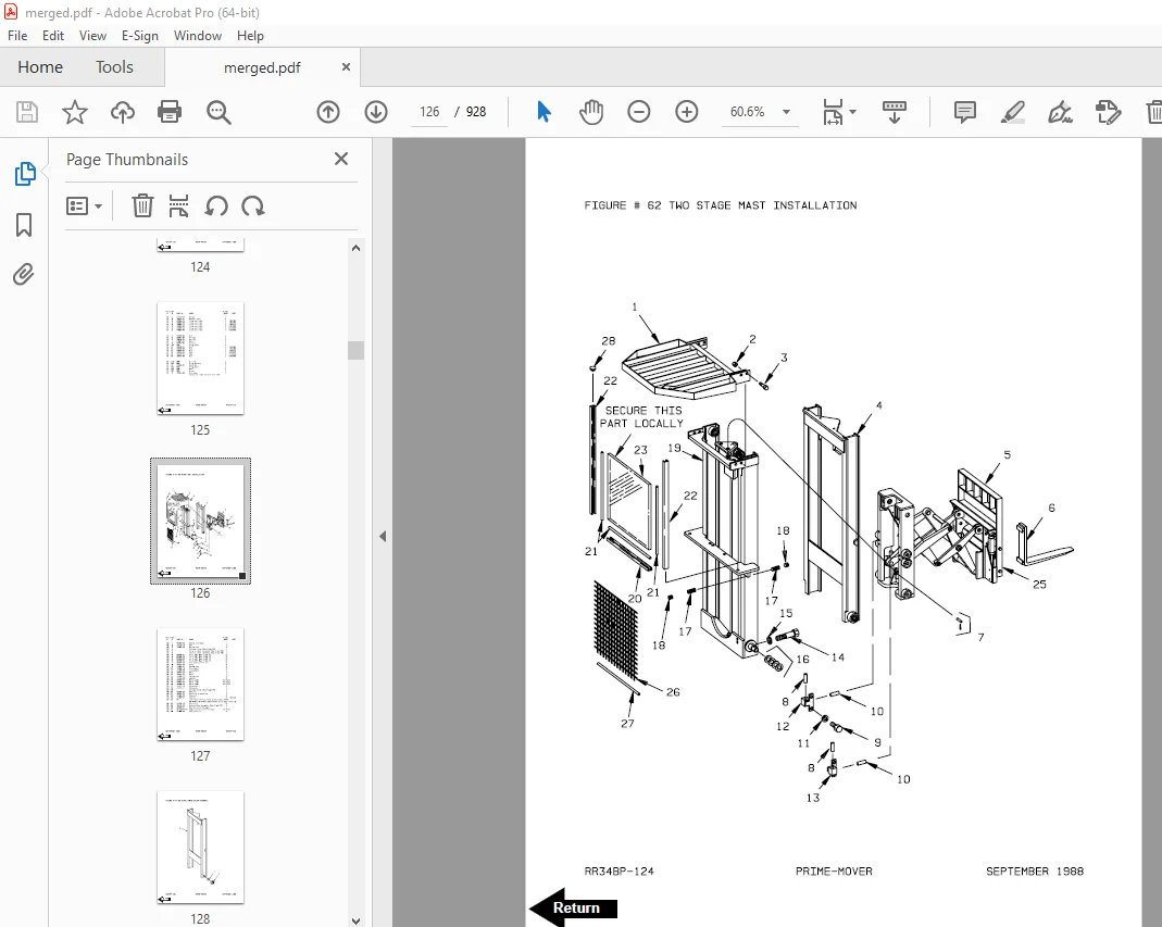
Figure # 62 Two Stage Mast Installation 126
Figure # 63 Two Stage Inner Column Assembly 128
Figure # 64 Two Stage Outer Column Assembly 130
Figure # 65 Two Stage Cylinder Installation 132
Figure # 66 Single Reach Assembly 134
Figure # 67 Single Reach Front Frame 136
Figure # 68 Double Reach Assembly 138
Figure # 69 Double Reach Front Frame 140
Figure # 70 Sideshifter Assembly 142
Figure # 71 Fork Assembly 144
Figure # 72 Three Stage Mast Installation 146
Figure # 73 Three Stage Outer Column Assembly 148
Figure # 74 Three Stage Intermediate Column Assembly 150
Figure # 75 Three Stage Inner Column Assembly 152
Figure # 76 Three Stage Freelift Cylinder Installation 154
Figure # 77 Main Frame and Load Wheel Assembly 156
Figure # 78 Single Load Wheel Assembly 158
Figure # 79 5″ High Articulating Load Wheel Assembly 160
Figure # 80 4″ High Articulating Load Wheel Assembly 162
Figure # 81 Caster Assembly 164
Figure # 82 Special Tools and Lubrications 166
Numerical Index 168
Appendix 1 187
Figure # 1 EV-1 Electrical Schematic 188
Figure # 2 Electrical Schematic Symbols 189
Figure # 3 EV-1 Power Component Wiring 190
Figure # 4 EV-1 SCR and Contactor Panel Assembly 192
Figure # 5 EV-1 SCR Control 194
Figure # 6 EV-1 Transformer Assembly 196
Figure # 7 EV-1 Rectifier Heat Sink Assembly 198
Figure # 8 EV-1 Lift Pump and 1A Contactor Assembly 200
Figure # 9 EV-1 Steering Contactor Assembly 202
Figure # 10 Forward and Rearward Contactor Assembly 204
Back Cover 208
Front Cover 209
Parts Ordering Instructions 210
General Information 211
Alphabetical Index 212
Figure # 0 1 Decals and Parts Assembly 216
Figure # 0 2 Parts List Index 218
Figure # 1 1 Transmission and Drive Motor Installation 222
Figure # 1 2 Drive Motor and Brake Assembly 224
Figure # 1 3 Transmission Assembly (40011-01) Part # I) 226
Figure # 1 4 Transmission Assembly (40011-00) Part # II) 228
Figure # 2 1 “E” EV-100LX SCR Electrical Schematic 230
Figure # 2 2 “E” EV-100LX SCR Electrical Schematic Symbols 231
Figure # 2 3 “EE” EV-100LX SCR Electrical Schematic 232
Figure # 2 4 “EE” EV-100LX SCR Electrical Schematic Symbols 233
Figure # 2 5 Wiring Assembly for Cold Storage 234
Figure # 2 6 Wiring Harness Assembly 236
Figure # 2 7 Limit Switch Wiring Assembly 238
Figure # 2 8 Two Stage Mast Cable Assembly 240
Figure # 2 9 Three Stage Mast Cable Assembly 242
Figure # 2 10 Single Reach Cable Assembly 244
Figure # 2 11 Double Reach Cable Assembly 246
Figure # 2 12 EV-100LX Power Component Wiring 248
Figure # 2 13 EV-100LX TX SCR Control Panel Assembly (49399-00) & EV-100LX TT SCR Control Panel Assembly (49399-01) 250
Figure # 2 14 EV-100LX Contactor Panel Assembly & Related Parts for “E” and “EE” 252
Figure # 2 15 EV-100LX Contactor Panel Assembly (24 Volt, 41757-01) (36 Volt, 41757-02) 254
Figure # 2 16 EV-100LX SCR Forward & Rearward Contactor Assembly (27692-00) 256
Figure # 2 17 EV-100LX SCR 1A Contactor Assembly (27693-02) 258
Figure # 2 18 Lift Pump Contactor Assembly (24 Volt, 27693-02) (36 Volt, 202169) 260
Figure # 2 19 EV-100LX SCR Auxiliary Pump Contactor Assembly (300073-000) 262
Figure # 2 20 Power Connector Assembly (24 Volt, 49855-24) (36 Volt, 49855-22) 264
Figure # 2 21 Lift Pump Motor Assembly, 24 Volt (27900-00, 5BT1324B54) G E & Lift Pump Motor Assembly, 36 Volt (27899-00, 5B 266
Figure # 2 22 Drive Motor Assembly, 24 Volt (27901-00, 5BT1326B235) G E & Drive Motor Assembly, 36 Volt (27902-00, 5BT1326B2 268
Figure # 2 23 Auxiliary Pump Motor Assembly 270
Figure # 2 24 Warning Light Assembly 272
Figure # 2 25 “E” EV-100LX TT SCR Electrical Schematic 274
Figure # 2 26 “E” EV-100LX TT SCR Electrical Schematic Symbols 275
Figure # 2 27 “EE” EV-100LX TT SCR Electrical Schematic 276
Figure # 2 28 “EE” EV-100LX TT SCR Electrical Schematic Symbols 277
Figure # 2 29 EV-100LX Dash Display Installation 278
Figure # 3 1 Hydraulic Schematic 280
Figure # 3 2 Hydraulic Schematic Symbols 281
Figure # 3 3 Auxiliary Pump and Reservoir Assembly 282
Figure # 3 4 Auxiliary Control Valve Assembly 284
Figure # 3 5 Auxiliary Pump and Motor Assembly 286
Figure # 3 6 Auxiliary Pump Assembly 288
Figure # 3 7 Hydraulic Reservoir Assembly 290
Figure # 3 8 Torque Generator Assembly 292
Figure # 3 9 Two Stage Mast Hydraulic Assembly 294
Figure # 3 10 Three Stage Mast Hydraulic Assembly 296
Figure # 3 11 Single Reach Reach Cylinder Hose Installation 298
Figure # 3 12 Single Reach Diverter Valve Assembly 300
Figure # 3 13 Single Reach Reach Cylinder Assembly 302
Figure # 3 14 Single Reach, Tilt and Sideshift Hose Installation 304
Figure # 3 15 Single Reach Tilt Cylinder Assembly 306
Figure # 3 16 Double Reach with Tilt and Sideshifter 308
Figure # 3 17 Double Reach Diverter Valve Assembly 310
Figure # 3 18 Double Reach Reach Cylinder Assembly 312
Figure # 3 19 Double Reach Tilt Cylinder Assembly 314
Figure # 3 20 Lift Pump and Reservoir Assembly 316
Figure # 3 21 Lift Pump Motor Assembly 318
Figure # 3 22 Lift Pump Motor Assembly, 24 Volt 320
Figure # 3 23 Lift Pump Motor Assembly, 36 Volt 322
Figure # 3 24 Lift Control Valve Assembly 324
Figure # 3 25 Two Stage Cylinder and Reservoir Assembly 326
Figure # 3 26 Two Stage Cylinder Assembly 328
Figure # 3 27 Three Stage Cylinder and Reservoir Assembly 330
Figure # 3 28 Three Stage Staging Cylinder Assembly 332
Figure # 3 29 Three Stage Freelift Cylinder Assembly 334
Figure # 4 1 Shielding Assembly 336
Figure # 4 2 Emergency Disconnect Assembly 338
Figure # 4 3 Auxiliary Control Assembly 340
Figure # 4 4 Hand Lift/Lower and Speed Control 342
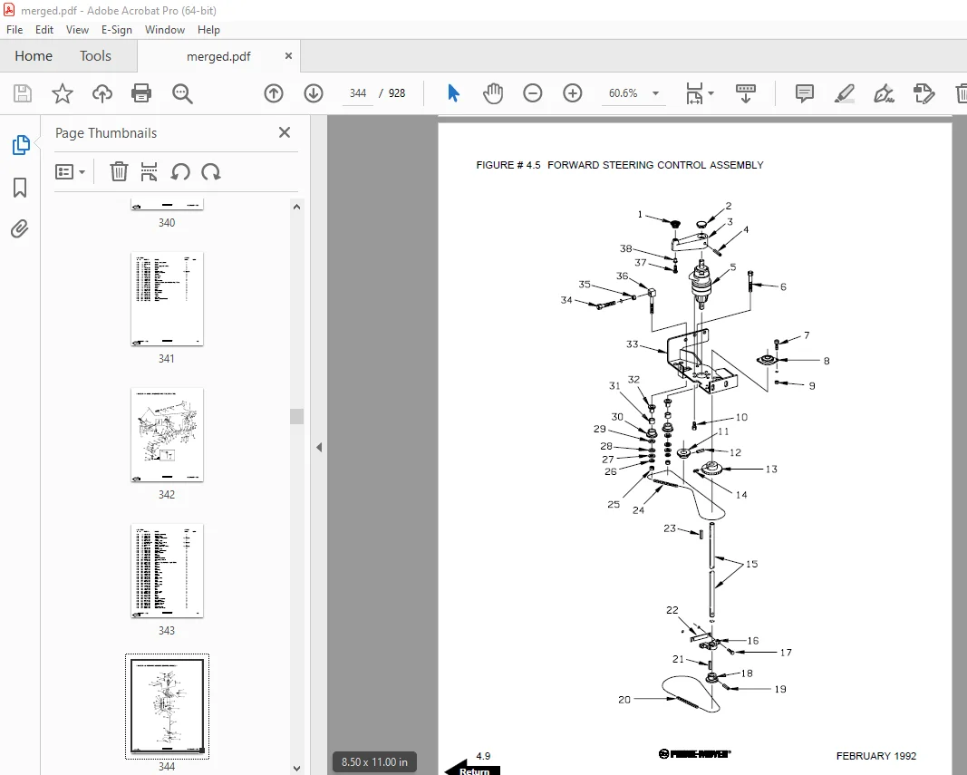
Figure # 4 5 Forward Steering Control Assembly 344
Figure # 4 6 Rearward Steering Control Assembly 346
Figure # 4 7 Auxiliary Pump and Motor Installation 348
Figure # 4 8 Main Frame and Load Wheel Assembly 350
Figure # 4 9 Single Load Wheel Assembly 352
Figure # 4 10 5″ High Articulating Load Wheel Assembly 354
Figure # 4 11 4″ High Articulating Load Wheel Assembly 356
Figure # 4 12 Caster Assembly 358
Figure # 5 1 Two Stage Mast Installation 360
Figure # 5 2 Two Stage Inner Column Assembly 362
Figure # 5 3 Two Stage Outer Column Assembly 364
Figure # 5 4 Two Stage Cylinder Installation 366
Figure # 5 5 Two Stage Single Reach Assembly 368
Figure # 5 6 Two Stage Single Reach Front Frame Assembly 370
Figure # 5 7 Two Stage Double Reach Assembly 372
Figure # 5 8 Two Stage Double Reach Front Frame Assembly 374
Figure # 5 9 Two Stage Sideshifter Assembly 376
Figure # 5 10 Two Stage Fork Assembly 378
Figure # 5 11 Three Stage Mast Installation 380
Figure # 5 12 Three Stage Inner Column Assembly 382
Figure # 5 13 Three Stage Freelift Cylinder Installation 384
Figure # 5 14 Three Stage Intermediate Column Assembly 386
Figure # 5 15 Three Stage Outer Column Assembly 388
Figure # 5 16 Three Stage Single Reach Assembly 390
Figure # 5 17 Three Stage Single Reach Front Frame Assembly 392
Figure # 5 18 Three Stage Double Reach Assembly 394
Figure # 5 19 Three Stage Double Reach Front Frame Assembly 396
Figure # 5 20 Three Stage Sideshifter Assembly 398
Figure # 5 21 Three Stage Fork Assembly 400
Figure # 6 1 Manlift EV-100 LX SCR Electrrical Schematic 402
Figure # 6 2 Manlift EV-100 LX SCR Electrical Schematic Symbols 403
Figure # 6 3 Three Stage Fork Assembly 404
Figure # 6 4 Manlift Three Stage Mast Cable Assembly 406
Figure # 6 5 Manlift Reach and Platform Cable Assembly 408
Figure # 6 6 Manlift Power Component Wiring 410
Figure # 6 7 Manlift Connector Assembly 412
Figure # 6 8 Manlift Hydraulic Schematic 414
Figure # 6 9 Manlift Hydraulic Schematic Symbols 415
Figure # 6 10 Manlift Hydraulic Diagram 416
Figure # 6 11 Block Manlift Valve Assembly 418
Figure # 6 12 Manlift Valve Assembly 420
Figure # 6 13 Manlift Load Backrest Installation 422
Figure # 7 1 Battery Lift Interrupt “E” EV-100LX SCR Electrical Schematic 424
Figure # 7 2 Battery Lift Interrupt “E” EV-100LX SCR Electrical Schematic Symbols 425
Figure # 7 3 Battery Lift Interrupt “EE” EV-100LX SCR Electrical Schematic 426
Figure # 7 4 Battery Lift Interrupt “EE” EV-100LX SCR Electrical Schematic Symbols 427
Figure # 7 5 Battery Lift Interrupt Installation 428
Figure # 10 1 Special Tools and Lubrications 430
Numerical Index 433
Back Cover 454
Front Cover 455
Parts Ordering Instructions 456
Field Modifications 456
General Information 457
Alphabetical Index 458
Section 0 0 462
Figure # 0 1 Decals and Parts Assembly 462
Section 1 0 464
Figure # 1 1 Transmission and Drive Motor Installation 464
Figure # 1 2 Drive Motor and Brake Assembly 466
Figure # 1 3 Transmission Assembly Part # 1 468
Figure # 1 4 Transmission Assembly Part # 2 470
Section 2 0 472
Figure # 2 1 “E” EV-100LX SCR Electrical Schematic 472
Figure # 2 2 “E” EV-100LX SCR Electrical Schematic Symbols 473
Figure # 2 3 “EE” EV-100LX SCR Electrical Schematic 474
Figure # 2 4 “EE” EV-100LX SCR Electrical Schematic Symbols 475
Figure # 2 5 Wiring Assembly for Cold Storage 476
Figure # 2 6 Wiring Harness Assembly 478
Figure # 2 7 Limit Switch Wiring Assembly 480
Figure # 2 8 Two Stage Mast Cable Assembly 482
Figure # 2 9 Three Stage Mast Cable Assembly 484
Figure # 2 10 Reach Cable Assembly 486
Figure # 2 11 EV-100LX Power Component Wiring 488
Figure # 2 12 EV-100LX TX & TT SCR Control Panel Assembly 490
Figure # 2 13 EV-100LX Contactor Panel Assembly & Related Parts for “E” and “EE” 492
Figure # 2 14 EV-100LX Contactor Panel Assembly 494
Figure # 2 15 EV-100LX SCR Forward & Rearward Contactor Assembly 496
Figure # 2 16 EV-100LX SCR 1A Contactor Assembly 498
Figure # 2 17 Lift Pump Contactor Assembly 500
Figure # 2 18 EV-100LX SCR Auxiliary Pump Contactor Assembly 502
Figure # 2 19 Power Connector Assembly 504
Figure # 2 20 “E” & “EE” 24 Volt Lift Pump Motor Assy 506
Figure # 2 21 “E” 36 Volt Lift Pump Motor Assy 508
Figure # 2 22 “EE” 36 Volt Lift Pump Motor Assembly 510
Figure # 2 23 Drive Motor Assembly 512
Figure # 2 24 Auxiliary Pump Motor Assembly 514
Figure # 2 25 Warning Light Assembly 516
Figure # 2 26 “E” EV-100LX TT SCR Electrical Schematic 518
Figure # 2 27 “E” EV-100LX TT SCR Electrical Schematic Symbols 519
Figure # 2 28 “EE” EV-100LX TT SCR Electrical Schematic 520
Figure # 2 29 “EE” EV-100LX TT SCR Electrical Schematic Symbols 521
Figure # 2 30 EV-100LX Dash Display Installation 522
Figure # 2 31 EV-100LX SCR Electrical Schematic – 3 Function Control Handle 524
Figure # 2 32 EV-100LX SCR Electrical Schematic Symbols 525
Figure # 2 33 Wiring Harness Assembly for 3 Function Control Valve 526
Section 3 0 528
Figure # 3 1 Hydraulic Schematic 528
Figure # 3 2 Hydraulic Schematic Symbols 529
Figure # 3 3 Auxiliary Pump and Reservoir Assembly 530
Figure # 3 4 Auxiliary control Valve Assembly 532
Figure # 3 5 Auxiliary Pump and Motor Assembly 534
Figure # 3 6 Auxiliary Pump Assembly 536
Figure # 3 7 Hydraulic Reservoir Assembly 538
Figure # 3 8 Torque Generator Assembly 540
Figure # 3 9 Two Stage Mast Hydraulic Assembly 542
Figure # 3 10 Three Stage Mast Hydraulic Assembly 544
Figure # 3 11 Single Reach, Reach Cylinder Hose Installation 546
Figure # 3 12 Reach Diverter Valve Assembly 548
Figure # 3 13 Reach Cylinder Assembly 550
Figure # 3 14 Tilt and Sideshift Hose Installation 552
Figure # 3 15 Tilt Cylinder Assembly 554
Figure # 3 16 Lift Pump and Reservoir Assembly 556
Figure # 3 17 Lift Pump Motor Assembly 558
Figure # 3 18 Lift Pump Motor Assembly, 24 Volt 560
Figure # 3 19 Lift Pump Motor Assembly, 36 Volt 562
Figure # 3 20 Lift Control Valve Assembly 564
Figure # 3 21 Two Stage Cylinder and Reservoir Assembly 566
Figure # 3 22 Two Stage Cylinder Assembly 568
Figure # 3 23 Three Stage Cylinder and Reservoir Assembly 570
Figure # 3 24 Three Stage Staging Cylinder Assembly 572
Figure # 3 25 Three Stage Freelift Cylinder Assembly 574
Figure # 3 26 Hydraulic Schematic for 3 Function Control Handle 576
Figure # 3 27 Hydraulic Schematic Symbols 577
Figure # 3 28 Auxiliary Pump & Reservoir Assy for 3 Function Control Handle 578
Figure # 3 29 Valve Assembly 580
Figure # 3 30 Two Stage Mast Hydraulic Assy for 3 Function Control Handle 582
Figure # 3 31 Three Stage Mast Hydraulic Assy for 3 Function Control Handle 584
Section 4 0 586
Figure # 4 1 Shielding Assembly 586
Figure # 4 2 Emergency Disconnect Assembly 588
Figure # 4 3 Auxiliary Control Assembly 590
Figure # 4 4 Hand Lift/Lower and Speed Control 592
Figure # 4 5 Forward Steering Control Assembly 594
Figure # 4 6 Rearward Steering Control Assembly 596
Figure # 4 7 Auxiliary Pump and Motor Installation 598
Figure # 4 8 Main Frame and Load Wheel Assembly 600
Figure # 4 9 Single Load Wheel Assembly 602
Figure # 4 10 5″ High Articulating Load Wheel Assembly 604
Figure # 4 11 4″ High Articulating Load Wheel Assembly 606
Figure # 4 12 Caster Assembly 608
Figure # 4 13 Hand Lift/Lower and Speed Control for 3 Function Control 610
Section 5 0 612
Figure # 5 1 Two Stage Mast Installation 612
Figure # 5 2 Two Stage Inner Column Assembly 614
Figure # 5 3 Two Stage Outer Column Assembly 616
Figure # 5 4 Two Stage Cylinder Assembly 618
Figure # 5 5 Two Stage Reach Assembly 620
Figure # 5 6 Two Stage Reach Front Frame 622
Figure # 5 7 Two Stage Sideshifter Assembly 624
Figure # 5 8 Two Stage Fork Assembly 626
Figure # 5 9 Three Stage Mast Installation 628
Figure # 5 10 Three Stage Inner Column Assembly 630
Figure # 5 11 Three Stage Freelift Cylinder Installation 632
Figure # 5 12 Three Stage Intermediate Column Assembly 634
Figure # 5 13 Three Stage Outer Column Assembly 636
Figure # 5 14 Three Stage Single Reach Assembly 638
Figure # 5 15 Three Stage Single Reach Front Frame Assembly 640
Figure # 5 16 Three Stage Sideshifter Assy 642
Figure # 5 17 Three Stage Fork Assembly 643
Section 7 0 645
Figure # 7 1 Battery Lift Interrupt “E” EV-100LX SCR Electrical Schematic 645
Figure # 7 2 Battery Lift Interrupt “E” EV-100LX SCR Electrical Schematic Symbols 646
Figure # 7 3 Battery Lift Interrupt “EE” EV-100LX SCR Electrical Schematic 647
Figure # 7 4 Battery Lift Interrupt “EE” EV-100LX SCR Electrical Schematic Symbols 648
Figure # 7 5 Battery Lift Interrupt Installation 649
Section 10 0 651
Figure # 10 1 Special Tools and Lubrications 651
Numerical Index 654
Back Cover 674
Front Cover 675
Parts Ordering Instructions 676
General Information 677
Alphabetical Index 678
Figure # 0 1 Decals and Parts Assembly 682
Figure # 1 1 Transmission and Drive Motor Installation 684
Figure # 1 2 Drive Motor and Brake Assembly 686
Figure # 1 3 Transmission Assembly 688
Figure # 1 4 Transmission Assembly 690
Figure # 2 1 “E” EV-100LX SCR Electrical Schematic 692
Figure # 2 2 “E” EV-100LX SCR Electrical Schematic Symbols 693
Figure # 2 3 “EE” EV-100LX SCR Electrical Schematic 694
Figure # 2 4 “EE” EV-100LX SCR Electrical Schematic Symbols 695
Figure # 2 5 Wiring Assembly for Cold Storage 696
Figure # 2 6 Wiring Harness Assembly 698
Figure # 2 7 Limit Switch Wiring Assembly 700
Figure # 2 8 Two Stage Mast Cable Assembly 702
Figure # 2 9 Three Stage Mast Cable Assembly 704
Figure # 2 10 Reach Cable Assembly 706
Figure # 2 11 EV-100LX Power Component Wiring 708
Figure # 2 12 EV-100LX TX & TT SCR Control Panel Assembly 710
Figure # 2 13 EV-100LX Contactor Panel Assembly & Related Parts for “E” and “EE” 712
Figure # 2 14 EV-100LX Contactor Panel Assembly, 24 & 36 Volt 714
Figure # 2 15 EV-100LX SCR Forward & Rearward Contactor Assembly 716
Figure # 2 16 EV-100LX SCR 1A Contactor Assembly 718
Figure # 2 17 Lift Pump Contactor Assembly, 24 & 36 Volt 720
Figure # 2 18 EV-100LX SCR Auxiliary Pump Contactor Assembly 722
Figure # 2 19 Power Connector Assembly, 24 & 36 Volt 724
Figure # 2 20 Lift Pump Motor Assembly, 24 & 36 Volt 726
Figure # 2 20A Lift Pump Motor Assembly, 36 Volt 728
Figure # 2 21 Drive Motor Assembly, 24 & 36 Volt 730
Figure # 2 22 Auxiliary Pump Motor Assembly, 24 & 36 Volt 732
Figure # 2 23 Warning Light Assembly, 24 & 36 Volt 734
Figure # 2 24 “E” EV-100LX TT SCR Electrical Schematic 736
Figure # 2 25 “E” EV-100LX TT SCR Electrical Schematic Symbols 737
Figure # 2 26 “EE” EV-100LX TT SCR Electrical Schematic 738
Figure # 2 27 “EE” EV-100LX TT SCR Electrical Schematic Symbols 739
Figure # 2 28 EV-100LX Dash Display Installation 740
Figure # 2 29A TX EV-100LX Electrical Schematic – 3 Function Control Handle 742
Figure # 2 30A EV-100LX SCR Electrical Schematic Symbols 743
Figure # 2 29B TT EV-100LX Electrical Schematic – 3 Function Control Handle 744
Figure # 2 30B EV-100LX SCR Electrical Schematic Symbols 745
Figure # 2 31 Wiring Harness Assembly for 3 Function Control Valve 746
Figure # 3 1 Hydraulic Schematic 748
Figure # 3 2 Hydraulic Schematic Symbols 749
Figure # 3 3 Auxiliary Pump and Reservoir Assembly 750
Figure # 3 4 Auxiliary Control Valve Assembly 752
Figure # 3 5 Auxiliary Pump and Motor Assembly, 24 & 36 Volt 754
Figure # 3 6 Auxiliary Pump Assembly 756
Figure # 3 7 Hydraulic Reservoir Assembly 758
Figure # 3 8 Torque Generator Assembly 760
Figure # 3 9 Two Stage Mast Hydraulic Assembly 762
Figure # 3 10 Three Stage Mast Hydraulic Assembly 764
Figure # 3 11 Single Reach, Reach Cylinder Hose Installation 766
Figure # 3 12 Reach Diverter Valve Assembly 768
Figure # 3 13 Reach Cylinder Assembly 770
Figure # 3 14 Tilt and Sideshift Hose Installation 772
Figure # 3 15 Tilt Cylinder Assembly 774
Figure # 3 16 Lift Pump and Reservoir Assembly 776
Figure # 3 17 Lift Pump Motor Assembly 778
Figure # 3 18 Lift Pump Assembly 780
Figure # 3 19 Lift Pump Motor Assembly, 36 Volt 782
Figure # 3 20 Lift Control Valve Assembly 784
Figure # 3 21 Two Stage Cylinder and Reservoir Assembly 786
Figure # 3 22 Two Stage Cylinder Assembly 788
Figure # 3 23 Three Stage Cylinder and Reservoir Assembly 790
Figure # 3 24 Three Stage Staging Cylinder Assembly 792
Figure # 3 25 Three Stage Freelift Cylinder Assembly 794
Figure # 3 26 Hydraulic Schematic for 3 Function Control Handle 796
Figure # 3 27 Hydraulic Schematic Symbols 797
Figure # 3 28 Auxiliary Pump & Reservoir Assy for 3 Function Control Handle 798
Figure # 3 29 Valve Assembly 800
Figure # 3 30 Two Stage Mast Hydraulic Assy for 3 Function Control Handle 802
Figure # 3 31 Three Stage Mast Hydraulic Assy for 3 Function Control Handle 804
Figure # 4 1 Shielding Assembly 806
Figure # 4 2 Emergency Disconnect Assembly 808
Figure # 4 3 Auxiliary Control Assembly 810
Figure # 4 4 Hand Lift/Lower and Speed Control 812
Figure # 4 5 Forward Steering Control Assembly 814
Figure # 4 6 Rearward Steering Control Assembly 816
Figure # 4 7 Auxiliary Pump and Motor Installation 818
Figure # 4 8 Main Frame and Load Wheel Assembly 820
Figure # 4 9 Single Load Wheel Assembly 822
Figure # 4 9A Single Load Wheel Assembly 824
Figure # 4 10 5″ High Articulating Load Wheel Assembly 826
Figure # 4 10A 5″ High Articulating Load Wheel Assembly 828
Figure # 4 11 4″ High Articulating Load Wheel Assembly 830
Figure # 4 11A 4″ High Articulating Load Wheel Assembly 832
Figure # 4 12 Caster Assembly 834
Figure # 4 13 Hand Lift/Lower and Speed Control for 3 Function Control 836
Figure # 5 1 Two Stage Mast Installation 838
Figure # 5 2 Two Stage Inner Column Assembly 840
Figure # 5 3 Two Stage Outer Column Assembly 842
Figure # 5 4 Two Stage Cylinder Assembly 844
Figure # 5 5 Two Stage Reach Assembly 846
Figure # 5 6 Two Stage Reach Front Frame 848
Figure # 5 7 Two Stage Sideshifter Assembly 850
Figure # 5 8 Two Stage Fork Assembly 852
Figure # 5 9 Three Stage Mast Installation 854
Figure # 5 10 Three Stage Inner Column Assembly 856
Figure # 5 11 Three Stage Freelift Cylinder Installation 858
Figure # 5 12 Three Stage Intermediate Column Assembly 860
Figure # 5 13 Three Stage Outer Column Assembly 862
Figure # 5 14 Three Stage Reach Assembly 864
Figure # 5 15 Three Stage Reach Front Frame Assembly 866
Figure # 5 16 Three Stage Sideshifter Assy 868
Figure # 5 17 Three Stage Fork Assembly 870
Figure # 6 1 Remote Lift/Lower EV-100 LX SCR Electrical Schematic 872
Figure # 6 2 Remote Lift/Lower EV-100 LX SCR Electrical Schematic Symbols 873
Figure # 6 3 Remote Lift/Lower Wiring Harness Assembly 874
Figure # 6 4 Remote Lift/Lower Three Stage Mast Cable Assembly 876
Figure # 6 5 Remote Lift/Lower Reach and Platform Cable Assembly 878
Figure # 6 6 Remote Lift/Lower Power Component Wiring 880
Figure # 6 7 Remote Lift/Lower Connector Assembly 882
Figure # 6 8 Remote Lift/Lower Hydraulic Schematic 884
Figure # 6 9 Remote Lift/Lower Manlift Hydraulic Schematic Symbols 885
Figure # 6 10 Remote Lift/Lower Hydraulic Diagram 886
Figure # 6 11 Blocking Remote Lift/Lower Valve Assembly 888
Figure # 6 12 Remote Lift/Lower Valve Assembly 890
Figure # 6 13 Remote Lift/Lower Load Backrest Installation 892
Figure # 6 14 Remote Lift/Lower Contactor Assembly 894
Figure # 7 1 Battery Lift Interrupt “E” EV-100LX SCR Electrical Schematic 896
Figure # 7 2 Battery Lift Interrupt “E” EV-100LX SCR Electrical Schematic Symbols 897
Figure # 7 3 Battery Lift Interrupt “EE” EV-100LX SCR Electrical Schematic 898
Figure # 7 4 Battery Lift Interrupt “EE” EV-100LX SCR Electric Schematic Symbols 899
Figure # 7 5 Battery Lift Interrupt Installation 900
Figure # 10 1 Special Tools and Lubrications 902
Numerical Index 905
Back Cover 928
DESCRIPTION:
BT Prime-Mover RR-34B Reach Truck Parts Manual – PDF DOWNLOAD
Effective Serial Number RR34B181728
PARTS ORDERING INSTRUCTIONS:
HOW TO ORDER:
- When you order, supply the part number, quantity, model and serial numbers of your machine. Supplying this information will assure prompt, efficient handling of your order. The pictorial reference number is not needed and including it can only add confusion.
- Since your dealer carries many parts in stock and maintains up-to-date prices on all parts, he will be able to process your order immediately. If, for some reason, the part is not in stock, he will order it from the factory. In either event, he maintains a current file of service manuals, which give all available parts ordering or technical information.
- All prices are FOB factory in Muscatine, Iowa. Shipping charges are added to the price of the part shipping from the factory.
WHERE TO ORDER:
Always order parts from the dealer who sold you your Prime-Mover. If it is necessary for the dealer to order parts from the factory, he is able to get prompt service for you. Parts are shipped in accordance with shipping instructions given on the order.
S.V 31/01/2025