BT Prime-Mover RR-45Z Reach Truck Parts Manual – PDF DOWNLOAD
$29.95
BT Prime-Mover RR-45Z Reach Truck Parts Manual – PDF DOWNLOAD
Manual Number 9101
Manual Part Number 301185-000
Effective Serial Number RR45Z0207217
Description
BT Prime-Mover RR-45Z Reach Truck Parts Manual – PDF DOWNLOAD
FILE DETAILS:
BT Prime-Mover RR-45Z Reach Truck Parts Manual – PDF DOWNLOAD
Language : English
Pages : 409
Downloadable : Yes
File Type : PDF
IMAGES PREVIEW OF THE MANUAL:
TABLE OF CONTENTS:
BT Prime-Mover RR-45Z Reach Truck Parts Manual – PDF DOWNLOAD
Manual Number 9101
Manual Part Number 301185-000
Effective Serial Number RR45Z0207217
Front Cover 1
Parts Ordering Instructions 2
General Information 3
Figure # 0 1 Decal and Parts Assembly 4
Figure # 0 2 Parts List and Figure Number Index 6
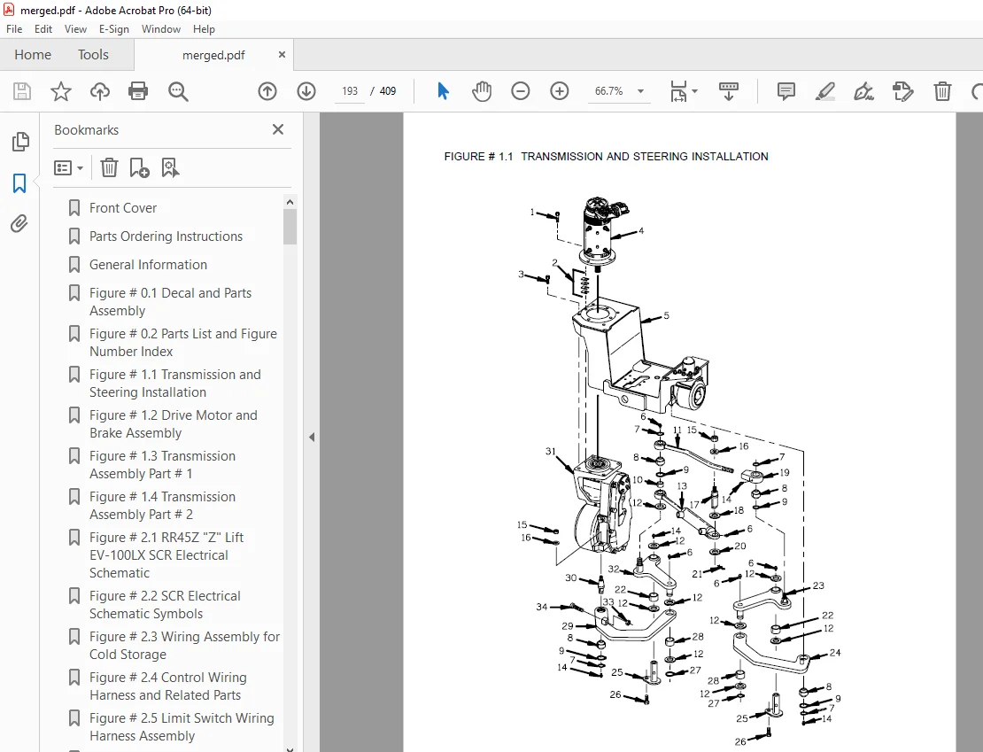
Figure # 1 1 Transmission and Steering Installation 8
Figure # 1 2 Drive Motor and Brake Assembly 10
Figure # 1 3 Transmission Assembly Part # 1 12
Figure # 1 4 Transmission Assembly Part # 2 14
Figure # 2 1 RR45Z “Z” Lift EV-100LX SCR Electrical Schematic 16
Figure # 2 2 SCR Electrical Schematic Symbols 17
Figure # 2 3 Wiring Assembly for Cold Storage 18
Figure # 2 4 Control Wiring Harness and Related Parts 20
Figure # 2 5 Limit Switch Wiring Harness Assembly 22
Figure # 2 6 Three Stage Mast Cable Assembly 24
Figure # 2 7 Single Reach Cable Assembly 26
Figure # 2 8 Double Reach Cable Assembly 28
Figure # 2 9 EV-100LX Power Component Wiring 30
Figure # 2 10 EV-100LX TX & TT SCR Control Panel 32
Figure # 2 11 Contactor Panel Assembly & Related Parts 34
Figure # 2 12 EV-100LX Contactor Panel Assembly 36
Figure # 2 13 Forward & Rearward Contactor Assembly 38
Figure # 2 14 1A Contactor Assembly 40
Figure # 2 15 Lift Pump Contactor Assembly 42
Figure # 2 16 Auxiliary Pump Contactor Assembly 44
Figure # 2 17 Power Connector Assembly 46
Figure # 2 18 Lift Pump Motor Assembly 48
Figure # 2 19 Drive Motor Assembly 50
Figure # 2 20 Auxiliary Pump Motor Assembly 52
Figure # 2 21 Warning Light Assembly 54
Figure # 2 22 EV-100LX TT Electrical Schematic 56
Figure # 2 23 EV-100LX TT Electrical Schematic Symbols 57
Figure # 2 24 EV-100LX Dash Display Installation 58
Figure # 3 1 RR45Z “Z” Lift EV-100LX Hydraulic Schematic 60
Figure # 3 2 Hydraulic Schematic Symbols 61
Figure # 3 3 Auxiliary Pump and Reservoir Assembly 62
Figure # 3 4 Auxiliary Control Valve Assembly 64
Figure # 3 5 Auxiliary Pump Assembly 66
Figure # 3 6 Hydraulic Reservoir Assembly 68
Figure # 3 7 Steering Control Valve Assembly 70
Figure # 3 8 Steering Control Valve and Hose Assembly 72
Figure # 3 9 Steering Cylinder Assembly 74
Figure # 3 10 “Z” Lift EV-100LX Three Stage Mast Hydraulic Assembly 76
Figure # 3 11 Single Reach, Reach Cylinder Hose Installation 78
Figure # 3 12 Single Reach Diverter Valve Assembly 80
Figure # 3 13 Single Reach, Reach Cylinder Assembly 82
Figure # 3 14 Single Reach, Tilt and Sideshifter 84
Figure # 3 15 Single Reach, Tilt Cylinder Assembly 86
Figure # 3 16 Double Reach with Tilt and Sideshifter 88
Figure # 3 17 Double Reach Diverter Valve Assembly 90
Figure # 3 18 Double Reach, Reach Cylinder Assembly 92
Figure # 3 19 Double Reach, Tilt Cylinder Assembly 94
Figure # 3 20 Lift Pump and Reservoir Assembly 96
Figure # 3 21 Lift Pump and Motor Assembly 98
Figure # 3 22 Lift Pump Assembly 100
Figure # 3 23 Lift Control Valve Assembly 102
Figure # 3 24 Three Stage Cylinder and Reservoir Assembly 104
Figure # 3 25 Three Stage Staging Cylinder Assembly 106
Figure # 3 26 Three Stage Freelift Cylinder Assembly 108
Figure # 3 27 Brake Master Cylinder 110
Figure # 3 28 Drive Motor Brake Cylinder 112
Figure # 3 29 Idler Wheel Brake Cylinder 114
Figure # 4 1 Shielding Assembly 116
Figure # 4 2 Emergency Disconnect Assembly 118
Figure # 4 3 Auxiliary Control Assembly 120
Figure # 4 4 Hand Lift/Lower and Speed Control 122
Figure # 4 5 Brake Linkage and Cylinder Assembly 124
Figure # 4 6 Steering Control Assembly 126
Figure # 4 7 Idler Wheel Installation 128
Figure # 4 8 Idler Wheel Assembly 130
Figure # 4 9 Main Frame and Load Wheel 132
Figure # 4 10 Single Load Wheel Assembly 134
Figure # 4 11 5″ High Articulating Load Wheel Assembly 136
Figure # 4 12 4″ High Articulating Load Wheel 138
Figure # 5 1 Three Stage Mast Installation 140
Figure # 5 2 Three Stage Inner Column Assembly 142
Figure # 5 3 Three Stage Freelift Cylinder Installation 144
Figure # 5 4 Three Stage Intermediate Column Assembly 146
Figure # 5 5 Three Stage Outer Column Assembly 148
Figure # 5 6 Single Reach Assembly 150
Figure # 5 7 Single Reach with Front Frame 152
Figure # 5 8 Double Reach Assembly 154
Figure # 5 9 Double Reach with Front Frame 156
Figure # 5 10 Sideshifter Assembly 158
Figure # 5 11 Fork Assembly 160
Figure # 7 1 Special Tools and Lubrications 162
Numerical Index 165
Front Cover 184
Parts Ordering Instructions 185
Field Modifications 185
General Information 186
Alphabetical Index 187
Figure # 0 1 Decals and Parts Assembly 191
Figure # 1 1 Transmission and Steering Installation 193
Figure # 1 2 Drive Motor Brake Assembly 195
Figure # 1 3 Transmission Assembly Part # 1 197
Figure # 1 4 Transmission Assembly Part # 2 199
Figure # 2 1 RR45Z “Z” Lift EV-100LX SCR Electrical Schematic 201
Figure # 2 2 RR45Z “Z” Lift EV-100LX SCR Electrical Schematic Symbols 202
Figure # 2 3 Wiring Assembly for Cold Storage 203
Figure # 2 4 RR45Z “Z” Lift Control Wiring Harness 205
Figure # 2 5 Limit Switch Wiring Assembly 207
Figure # 2 6 Three Stage Mast Cable Assembly 209
Figure # 2 7 Single Reach Cable Assembly 211
Figure # 2 8 Double Reach Cable Assembly 213
Figure # 2 9 EV-100LX Power Component Wiring 215
Figure # 2 10 EV-100LX TX & TT SCR Control Panel Assembly 217
Figure # 2 11 Contactor Panel Assembly & Related Parts 219
Figure # 2 12 EV-100LX Contactor Panel Assembly 221
Figure # 2 13 EV-100LX SCR Forward & Rearward Contactor Assembly 223
Figure # 2 14 EV-100LX SCR 1A Contactor Assembly 225
Figure # 2 15 Lift Pump Contactor Assembly 227
Figure # 2 16 EV-100LX SCR Auxiliary Pump Contactor Assembly 229
Figure # 2 17 Power Connector Assembly, 36 Volt 231
Figure # 2 18 Lift Pump Motor Assembly 233
Figure # 2 19 Drive Motor Assembly 235
Figure # 2 20 Auxiliary Pump Motor Assembly 237
Figure # 2 21 Warning Light Assembly 239
Figure # 2 22 EV-100LX TT Electrical Schematic 241
Figure # 2 23 EV-100LX TT Electrical Schematic Symbols 242
Figure # 2 24 EV-100LX Dash Display Installation 243
Figure # 2 25 EV-100LX SCR Electrical Schematic – 3 Function Control Handle 245
Figure # 2 26 EV-100LX SCR Electrical Schematic Symbols 246
Figure # 2 27 Wiring Harness Assembly for 3 Function Control Valve 247
Figure # 2 30 RR45 “Z” EV-100LX TT SCR Electrical Schematic – Three Function Control Handle 249
Figure # 2 31 EV-100LX SCR Electrical Schematic Symbols 250
Figure # 3 1 Hydraulic Schematic for 3 Function Control Handle 251
Figure # 3 2 Hydraulic Schematic Symbols 252
Figure # 3 3 Auxiliary Pump and Reservoir Assembly 253
Figure # 3 4 Auxiliary Control Valve Assembly (not used with multi-function handle) 255
Figure # 3 5 Auxiliary Pump and Motor Assembly 257
Figure # 3 6 Auxiliary Pump Assembly 259
Figure # 3 7 Hydraulic Reservoir Assembly 261
Figure # 3 8 Steering Control Valve Assembly 263
Figure # 3 9 Steering Control Valve and Hose Assembly 265
Figure # 3 10 Steering Cylinder Assembly 267
Figure # 3 11 Three Stage Mast Hydraulic Assembly 269
Figure # 3 12 Single Reach, Reach Cylinder Hose Installation 271
Figure # 3 13 Single Reach Diverter Valve Assembly 273
Figure # 3 14 Single Reach, Cushion Reach Cylinder Assembly 275
Figure # 3 15 Single Reach, Tilt and Sideshift Hose Installation 277
Figure # 3 16 Double Reach with Tilt and Sideshifter 279
Figure # 3 17 Double Reach, Reach Cylinder Assembly 281
Figure # 3 18 Double Reach Diverter Valve Assembly 283
Figure # 3 19 Double Reach, Tilt Cylinder Assembly 285
Figure # 3 20 Double Reach, Reach Cylinder Assembly 287
Figure # 3 21 Double Reach, Tilt Cylinder Assembly 289
Figure # 3 22 Lift Pump Motor and Reservoir Assembly 291
Figure # 3 23 Lift Pump Motor Assembly 293
Figure # 3 24 Lift Pump Motor Assembly, 24 Volt 295
Figure # 3 25 Lift Pump Motor Assembly, 36 Volt 297
Figure # 3 26 Lift Control Valve Assembly 299
Figure # 3 27 Three Stage Cylinder and Reservoir Assembly 301
Figure # 3 28 Three Stage Staging Cylinder Assembly 303
Figure # 3 29 Three Stage Freelift Cylinder Assembly 305
Figure # 3 30 Brake Linkage and Cylinder Assembly 307
Figure # 3 31 Brake Master Cylinder 309
Figure # 3 32 Drive Motor Brake Cylinder 311
Figure # 3 33 Idler Wheel Brake Cylinder 313
Figure # 3 36 Auxiliary Pump & Reservoir Assembly for 3 Function Control Handle 315
Figure # 3 37 Valve Assembly 317
Figure # 3 38 Three Stage Mast Hydraulic Assembly for 3 Function Control Handle 319
Figure # 4 1 Shielding Assembly 321
Figure # 4 2 Emergency Disconnect Assembly 323
Figure # 4 3 Auxiliary Control Assembly 325
Figure # 4 4 Hand Lift/Lower and Speed Control 327
Figure # 4 5 Steering Control Assembly 329
Figure # 4 6 Idler Wheel Installation 331
Figure # 4 7 Idler Wheel Assembly 333
Figure # 4 8 Main Frame and Load Wheel Assembly 335
Figure # 4 9 Single Load Wheel Assembly 337
Figure # 4 10 5″ High Articulating Load Wheel Assembly 339
Figure # 4 11 4″ High Articulating Load Wheel Assembly 341
Figure # 4 13 Hand Lift/Lower and Speed Control for 3 Function Control 343
Figure # 5 1 Three Stage Mast Installation 345
Figure # 5 2 Three Stage Inner Column Assembly 347
Figure # 5 3 Three Stage Freelift Cylinder Installation 349
Figure # 5 4 Three Stage Intermediate Column Assembly 351
Figure # 5 5 Three Stage Outer Column Assembly 353
Figure # 5 6 Single Reach Assembly 355
Figure # 5 7 Single Reach with Front Frame 357
Figure # 5 8 Double Reach Assembly 359
Figure # 5 9 Double Reach with Front Frame 361
Figure # 5 10 Sideshifter Assembly 363
Figure # 5 11 Fork Assembly 365
Figure # 6 1 Manlift EV-100 LX SCR Electrical Schematic 367
Figure # 6 2 Manlift EV-100 LX SCR Electrical Schematic Symbols 368
Figure # 6 3 Manlift Wiring Harness Assembly 369
Figure # 6 4 Manlift Three Stage Mast Cable Assembly 371
Figure # 6 5 Manlift Reach and Platform Cable Assembly 373
Figure # 6 6 Manlift Power Component Wiring 375
Figure # 6 7 Manlift Connector Assembly 377
Figure # 6 8 Manlift Hydraulic Schematic 379
Figure # 6 9 Manlift Hydraulic Schematic Symbols 380
Figure # 6 10 Manlift Hydraulic Diagram 381
Figure # 6 11 Blocking Manlift Valve Assembly 383
Figure # 6 12 Manlift Valve Assembly 385
Figure # 6 13 Manlift Load Backrest Installation 387
Figure # 10 1 Special Tools and Lubrications 389
Numerical Index 392
DESCRIPTION:
BT Prime-Mover RR-45Z Reach Truck Parts Manual – PDF DOWNLOAD
Manual Number 9101
Manual Part Number 301185-000
Effective Serial Number RR45Z0207217
PARTS ORDERING INSTRUCTIONS:
HOW TO ORDER:
- When you order, supply the part number, quantity, model and serial numbers of your machine. Supplying this information will assure prompt, efficient handling of your order. The pictorial reference number is not needed and including it can only add confusion.
- Since your dealer carries many parts in stock and maintains up-to-date prices on all parts, he will be able to process your order immediately. If, for some reason, the part is not in stock, he will order it from the factory. In either event, he maintains a current file of service manuals, which give all available parts ordering or technical information.
- All prices are FOB factory in Muscatine, Iowa. Shipping charges are added to the price of the part shipping from the factory.
WHERE TO ORDER
Always order parts from the dealer who sold you your PRIME-MOVER. If it is necessary for the dealer to order parts from the factory, he is able to get prompt service for you. Parts are shipped in accordance with shipping instructions given on the order.
S.V 21/01/2025