BT Prime-Mover SN-20 SN-30 SN-40 Electric Walkie Straddle Stacker Parts Manual PDF
$33.95
BT Prime-Mover SN-20 SN-30 SN-40 Electric Walkie Straddle Stacker Parts Manual – PDF DOWNLOAD
300380-000 1986_December
300380-001 1991_February
300380-002 1993_August
300380-003 1994_October
Description
BT Prime-Mover SN-20 SN-30 SN-40 Electric Walkie Straddle Stacker Parts Manual – PDF DOWNLOAD
FILE DETAILS:
BT Prime-Mover SN-20 SN-30 SN-40 Electric Walkie Straddle Stacker Parts Manual – PDF DOWNLOAD
Language : English
Pages : 874
Downloadable : Yes
File Type : PDF
IMAGES PREVIEW OF THE MANUAL:
TABLE OF CONTENTS:
BT Prime-Mover SN-20 SN-30 SN-40 Electric Walkie Straddle Stacker Parts Manual – PDF DOWNLOAD
Front Cover 2
Warranty 3
Parts Ordering Instructions 4
General Information 5
Figure # 1 Decal and Parts Assembly 7
Figure # 2 Parts List and Service Reference Index 9
Figure # 3 Shielding Assembly 11
Figure # 4 Carrier Frame Assembly 13
Figure # 5 Handle and Transmission Assembly 15
Figure # 6 Handle Assembly 17
Figure # 7 Master Control Switch Assembly 19
Figure # 8 22:1 Transmission Assembly Part # 1 21
Figure # 9 22:1 Transmission Assembly Part # 2 23
Figure # 10 22:1 Drive Motor Assembly 25
Figure # 11 Drive Motor 12 Volt 27
Figure # 12 Drive Motor 24 Volt 29
Figure # 13 Electrical Schematic 31
Figure # 14 Electrical Schematic Symbols 32
Figure # 15 Control Wiring Harness 33
Figure # 16 12 Volt Power Component Wiring 35
Figure # 17 24 Volt Power Component Wiring 37
Figure # 18 Control Panel Assembly 39
Figure # 19 GE Contactor Assembly 41
Figure # 20 GE Contactor Assembly 43
Figure # 21 Power Connector Assembly 45
Figure # 22 Hydraulic Schematic 47
Figure # 23 Hydraulic Schematic Symbols 48
Figure # 24 12/24 Volt Hydraulic Assembly 49
Figure # 25 12/24 Volt Reservoir Pump and Motor 51
Figure # 26 12/24 Volt Pump and Motor Assembly 53
Figure # 27 Pump Motor Assembly 12 Volt and 24 Volt 55
Figure # 28 24 Volt Hydraulic Assembly 57
Figure # 29 24 Volt Reservoir Assembly 59
Figure # 30 24 Volt Pump and Motor Assembly 61
Figure # 31 Pump Assembly 63
Figure # 32 24 Volt Pump Assembly 65
Figure # 33 24 Volt Pump Motor Assembly 67
Figure # 34 24 Volt Pump Motor Assembly 69
Figure # 35 Lift Cylinder Assembly 71
Figure # 36 Manual Hydraulic Assembly 73
Figure # 37 Valve Mounting Assembly 75
Figure # 38 2 and 3 Spool Valve Assembly 77
Figure # 39 2 Stage Mast Installation Assembly 79
Figure # 40 2 Stage Inner Column Assembly 81
Figure # 41 2 Stage Cylinder Assembly and Related Parts 83
Figure # 42 2 Stage Standard Lift Frame and Load Backrest 85
Figure # 43 2 Stage ITA Lift Frame and Load Backrest 87
Figure # 44 Fork Assembly 89
Figure # 45 3 Stage Mast Installation Assembly 91
Figure # 46 3 Stage Outer Column Assembly 93
Figure # 47 3 Stage Intermediate Column Assembly 95
Figure # 48 3 Stage Inner Column Assembly 97
Figure # 49 3 Stage Cylinder Assembly and Related Parts 99
Figure # 50 3 Stage Cylinder Assembly 101
Figure # 51 3 Stage Lift Frame and Load Backrest 103
Figure # 52 Load Wheel Assembly 105
Figure # 53 Spring Loaded Caster Assembly 107
Figure # 54 Special Tools and Lubrications 109
Numerical Index 111
Back Cover 121
Front Cover 122
Parts Ordering Instructions 123
General Information 124
Figure # 0 1 Decals and Parts Assembly 125
Figure # 0 2 Parts List Index 127
Figure # 1 1 Transmission and Handle Assembly 131
Figure # 1 2 Standard Control Handle Assembly 133
Figure # 1 3 Thumb Control Handle Assembly 135
Figure # 1 4 Transmission Assembly, Part # 1 137
Figure # 1 5 Single Disc Brake Transmission Assembly 139
Figure # 1 6 Drive Motor Assembly 141
Figure # 2 1 Resistor Electrical Schematic 142
Figure # 2 2 Resistor Electrical Schematic Symbols 144
Figure # 2 3 Resistor Control Wiring Harness Assembly 145
Figure # 2 4 Resistor Power Component Wiring 147
Figure # 2 5 Control Panel Assembly 149
Figure # 2 6 Second Speed Contactor Assembly 151
Figure # 2 7 Forward & Rearward Contactor Assembly 153
Figure # 2 8 Power Connector Assembly 155
Figure # 2 9 Bosch Hydraulic Pump Motor Assembly 157
Figure # 2 10 12 Volt Drive Motor Assembly 159
Figure # 2 11 24 Volt Drive Motor Assembly 161
Figure # 2 12 Pump Motor Assembly 163
Figure # 2 13 Warning Light Assembly 165
SN-20 Hydraulic Section 168
Figure # 3 1 SN-20 Two Stage Hydraulic Schematic 169
Figure # 3 2 SN-20 Two Stage Hydraulic Schematic Symbols 170
Figure # 3 3 SN-20 12/24 Volt Two Stage Mast Hydraulic System 171
Figure # 3 4 SN-20 12/24 Volt Reservoir and Pump Assembly 173
Figure # 3 5 SN-20 Bosch Pump and Motor Assembly 175
Figure # 3 6 SN-20 Lift Cylinder Assembly 177
Figure # 3 7 SN-20 Three Stage Hydraulic Schematic 179
Figure # 3 8 SN-20 Three Stage Hydraulic Schematic Symbols 180
Figure # 3 9 SN-20 12/24 Volt Three Stage Mast Hydraulic System 181
Figure # 3 10 SN-20 12/24 Volt Reservoir and Pump Assembly 183
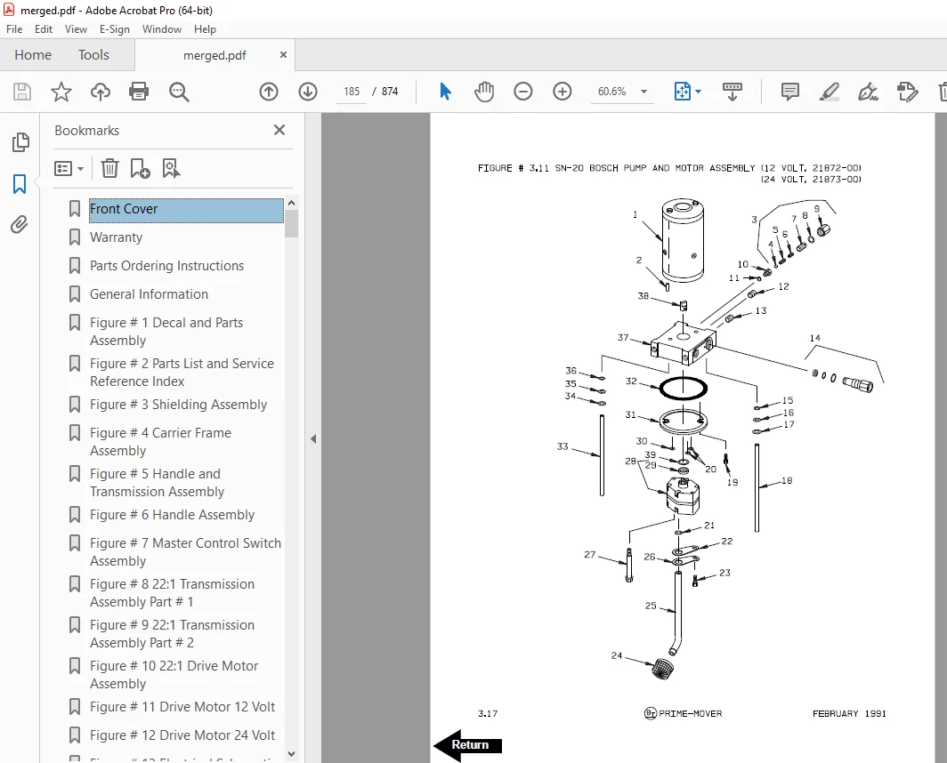
Figure # 3 11 SN-20 Bosch Pump and Motor Assembly 185
Figure # 3 12 SN-20 Three Stage Freelift Cylinder Assembly 187
Figure # 3 13 SN-20 Three Stage Freelift Cylinder Assembly 189
SN-30 Hydraulic Section 192
Figure # 3 14 SN-30 Two Stage Hydraulic Schematic 193
Figure # 3 15 SN-30 Two Stage Hydraulic Schematic Symbols 194
Figure # 3 16 SN-30 12 Volt Two Stage Mast Hydraulic System 195
Figure # 3 17 SN-30 Hydraulic Pump and Valve Installation, 24 Volt 197
Figure # 3 18 SN-30 12 Volt Reservoir and Pump Assembly 199
Figure # 3 19 SN-30 Two Stage Mast Bosch Pump and Motor Assembly 201
Figure # 3 20 SN-30 Two Stage Lift Cylinder Assembly 203
Figure # 3 21 SN-30 Two Stage Hydraulic Reservoir Assembly 205
Figure # 3 22 SN-30 24 Volt Lift Pump and Motor Assembly 207
Figure # 3 23 SN-30 24 Volt Lift Pump Assembly 209
Figure # 3 24 SN-30 Three Stage Hydraulic Schematic 211
Figure # 3 26 SN-30 12 Volt Three Stage Mast Hydraulic System 213
Figure # 3 27 SN-30 24 Volt Three Stage Hydraulic System, Part # 1 215
Figure # 3 28 SN-30 24 Volt Three Stage Mast Hydraulic System, Part # 2 217
Figure # 3 29 SN-30 12 Volt Reservoir and Pump Assembly 219
Figure # 3 30 SN-30 Bosch Pump and Motor Assembly 221
Figure # 3 31 SN-30 Three Stage Freelift Cylinder Assembly 223
Figure # 3 32 SN-30 Three Stage Freelift Cylinder Assembly 225
Figure # 3 33 SN-30 24 Volt Three Stage Hydraulic Reservoir Assembly 227
Figure # 3 34 SN-30 24 Volt Lift Pump and Motor Assembly 229
Figure # 3 35 SN-30 Lift Pump Assembly 231
Figure # 3 36 SN-30 Manual Hydraulic Schematic 233
Figure # 3 37 SN-30 Manual Hydraulic Schematic Symbols 234
Figure # 3 38 SN-30 Manual Hydraulic System – Part # 1 235
Figure # 3 39 SN-30 Manual Hydraulic System – Part # 2 237
Figure # 3 40 SN-30 Manual Lift Two Stage Lift Cylinder and Related Parts 239
Figure # 3 41 SN-30 Manual Lift Three Stage Lift Cylinders and Related Parts 241
Figure # 3 42 SN-30 Manual Two/Three Spool Control Valve Assembly 243
Figure # 3 43 SN-30 Manual Lift Pump and Motor Assembly 245
Figure # 3 44 SN-30 Manual Lift Pump Assembly 247
Figure # 3 45 SN-30 Manual Lift Hydraulic Reservoir Assembly 249
Figure # 3 46 SN-30 Manual Lift Two Stage Cylinder Assembly 251
Figure # 3 48 SN-30 Manual Lift Three Stage Freelift Cylinder Assembly 255
Figure # 3 47 SN-30 Manual Lift Three Stage Freelift Cylinder Assembly 253
SN-40 Hydraulic Section 258
Figure # 3 49 SN-40 Two Stage Hydraulic Schematic 259
Figure # 3 50 SN-40 Two Stage Hydraulic Schematic Symbols 260
Figure # 3 51 SN-40 Two Stage Hydraulic System – Part # 1 261
Figure # 3 52 SN-40 Two Stage Hydraulic System – Part # 2 263
Figure # 3 53 SN-40 Two Stage Lift Cylinder and Related Parts 265
Figure # 3 54 SN-40 Two/Three Spool Control Valve Assembly 267
Figure # 3 55 SN-40 Lift Pump and Motor Assembly 269
Figure # 3 56 SN-40 Lift Pump Assembly 271
Figure # 3 57 SN-40 Hydraulic Reservoir Assembly 273
Figure # 3 58 SN-40 Two Stage Lift Cylinder Assembly 275
Figure # 3 59 SN-40 Three Stage Hydraulic Schematic 277
Figure # 3 60 SN-40 Three Stage Hydraulic Schematic Symbols 278
Figure # 3 61 SN-40 Three Stage Hydraulic System – Part # 1 279
Figure # 3 62 SN-40 Three Stage Hydraulic System – Part # 2 281
Figure # 3 63 SN-40 Three Stage Lift Cylinders and Related Parts 283
Figure # 3 64 SN-40 Two/Three Spool Control Valve Assembly 285
Figure # 3 65 SN-40 Lift Pump and Motor Assembly 287
Figure # 3 66 SN-40 Lift Pump Assembly 289
Figure # 3 67 SN-40 Hydraulic Reservoir Assembly 291
Figure # 3 68 SN-40 Three Stage Staging Cylinder Assembly 293
Figure # 3 69 SN-40 Three Stage Freelift Cylinder Assembly 295
Figure # 4 1 Shielding Assembly 297
Figure # 4 2 Main Frame and Load Wheel Installation 299
Figure # 4 3 Caster Assembly 301
Figure # 4 4 Two/Three Spool Control Valve Mounting Assembly 303
Figure # 4 5 Pallet Centering Device 305
Figure # 5 1 SN-20/30 Two Stage Mast Installation 307
Figure # 5 2 SN-20/30 Two Stage Outer Column Assembly (Frame) 309
Figure # 5 3 SN-20/30 Two Stage Inner Column Assembly 311
Figure # 5 4 SN-20/30 Two Stage Mast Cylinder and Related Parts 313
Figure # 5 5 SN-20/30 Two Stage Mast Lift Frame and Load Backrest Assembly 315
Figure # 5 6 SN-20/30 Two Stage Fork Assembly 317
Figure # 5 7 SN-20/30 Three Stage Mast Installation 319
Figure # 5 8 SN-20/30 Three Stage Mast Outer Column Assembly 321
Figure # 5 9 SN-20/30 Three Stage Mast Intermediate Column Assembly 323
Figure # 5 10 SN-20/30 Three Stage Mast Inner Column Assembly 325
Figure # 5 11 SN-20/30 Three Stage Mast Freelift Cylinder and Related Parts 327
Figure # 5 12 SN-20/30 Three Stage Mast Lift Frame and Backrest Assembly 329
Figure # 5 13 SN-20/30 Three Stage Fork Assembly 331
Figure # 5 14 SN-40 Two Stage Mast Installation 333
Figure # 5 15 SN-40 Two Stage Mast Outer Column Assembly 335
Figure # 5 16 SN-40 Two Stage Mast Inner Column Assembly 337
Figure # 5 17 SN-40 Two Stage Mast Cylinder and Related Parts 339
Figure # 5 18 SN-40 Two Stage Mast Lift Frame and Load Backrest Assembly 341
Figure # 5 19 SN-40 Two Stage Fork Assembly 343
Figure # 5 20 SN-40 Three Stage Mast Installation 345
Figure # 5 21 SN-40 Three Stage Mast Outer Column Assembly 347
Figure # 5 22 SN-40 Three Stage Mast Intermediate Column Assembly 349
Figure # 5 23 SN-40 Three Stage Mast Inner Column Assembly 351
Figure # 5 24 SN-40 Three Stage Mast Freelift Cylinder Installation 353
Figure # 5 25 SN-40 Three Stage Mast Lift Frame and Load Backrest Assembly 355
Figure # 5 26 SN-40 Three Stage Fork Assembly 357
Figure # 7 1 Special Tools and Lubrications 359
Back Cover 361
Front Cover 362
Parts Ordering Instructions 363
General Information 364
Alphabetical Index 365
Figure # 0 1 Decals and Parts Assembly 369
Figure # 1 1 Transmission and Handle Assembly 371
Figure # 1 2 Twist Grip Resistor & Transistor Control Handle Assembly 373
Figure # 1 3 Thumb Control Resistor & Transistor Control Handle Assembly 375
Figure # 1 4 Transmission Assembly, Part # 1 377
Figure # 1 5 Transmission Assembly, Part # 2 379
Figure # 1 6 Drive Motor Assembly 381
Figure # 2 1 Resistor Electrical Schematic 383
Figure # 2 2 Resistor Electrical Schematic Symbols 384
Figure # 2 3 Resistor Control Wiring Harness Assembly 385
Figure # 2 4 Resistor Power Component Wiring 387
Figure # 2 5 Control Panel Assembly 389
Figure # 2 6 Second Speed Contactor Assembly 391
Figure # 2 7 Forward & Rearward Contactor Assembly 393
Figure # 2 8 Power Connector Assembly 395
Figure # 2 9 Bosch Hydraulic Pump Motor Assembly 397
Figure # 2 10 12 Volt Drive Motor Assembly 399
Figure # 2 11 24 Volt Drive Motor Assembly 401
Figure # 2 12 Pump Motor Assembly 403
Figure # 2 13 Warning Light Assembly 405
Figure # 2 14 Transistor Electrical Schematic 407
Figure # 2 15 Transistor Electrical Schematic Symbols 408
Figure # 2 16 Transistor Control Wiring Harness Assembly 409
Figure # 2 17 Control Wiring Harness 411
Figure # 2 18 Control Panel Assembly 413
SN-20 Hydraulic Section 416
Figure # 3 1 SN-20 Two Stage Hydraulic Schematic 417
Figure # 3 2 SN-20 Two Stage Hydraulic Schematic Symbols 418
Figure # 3 3 SN-20 12/24 Volt Two Stage Mast Hydraulic System 419
Figure # 3 4 SN-20 12/24 Volt Reservoir and Pump Assembly 421
Figure # 3 5 SN-20 Bosch Pump and Motor Assembly 423
Figure # 3 6 SN-20 Lift Cylinder Assembly 425
Figure # 3 7 SN-20 Three Stage Hydraulic Schematic 427
Figure # 3 8 SN-20 Three Stage Hydraulic Schematic Symbols 428
Figure # 3 9 SN-20 12/24 Volt Three Stage Mast Hydraulic System 429
Figure # 3 10 SN-20 12/24 Volt Reservoir and Pump Assembly 431
Figure # 3 11 SN-20 Bosch Pump and Motor Assembly 433
Figure # 3 12 SN-20 Three Stage Freelift Cylinder Assembly 435
Figure # 3 13 SN-20 Three Stage Freelift Cylinder Assembly 437
SN-30 Hydraulic Section 440
Figure # 3 14 SN-30 Two Stage Hydraulic Schematic 441
Figure # 3 15 SN-30 Two Stage Hydraulic Schematic Symbols 442
Figure # 3 16 SN-30 12 Volt Two Stage Mast Hydraulic System 443
Figure # 3 17 SN-30 Hydraulic Pump and Valve Installation, 24 Volt 445
Figure # 3 18 SN-30 12 Volt Reservoir and Pump Assembly 447
Figure # 3 19 SN-30 Two Stage Mast Bosch Pump and Motor Assembly 449
Figure # 3 20 SN-30 Two Stage Lift Cylinder Assembly 451
Figure # 3 21 SN-30 Two Stage Hydraulic Reservoir Assembly 453
Figure # 3 22 SN-30 24 Volt Lift Pump and Motor Assembly 455
Figure # 3 23 SN-30 24 Volt Lift Pump Assembly 457
Figure # 3 24 SN-30 Three Stage Hydraulic Schematic 459
Figure # 3 25 SN-30 Three Stage Hydraulic Schematic Symbols 460
Figure # 3 26 SN-30 12 Volt Three Stage Mast Hydraulic System 461
Figure # 3 27 SN-30 24 Volt Three Stage Hydraulic System, Part # 1 463
Figure # 3 28 SN-30 24 Volt Three Stage Mast Hydraulic System, Part # 2 465
Figure # 3 29 SN-30 12 Volt Reservoir and Pump Assembly 467
Figure # 3 30 SN-30 Bosch Pump and Motor Assembly 469
Figure # 3 31 SN-30 Three Stage Freelift Cylinder Assembly 471
Figure # 3 32 SN-30 Three Stage Freelift Cylinder Assembly 473
Figure # 3 33 SN-30 24 Volt Three Stage Hydraulic Reservoir Assembly 475
Figure # 3 34 SN-30 24 Volt Lift Pump and Motor Assembly 477
Figure # 3 35 SN-30 Lift Pump Assembly 479
Figure # 3 36 SN-30 Manual Hydraulic Schematic 481
Figure # 3 37 SN-30 Manual Hydraulic Schematic Symbols 482
Figure # 3 38 SN-30 Manual Hydraulic System – Part # 1 483
Figure # 3 39 SN-30 Manual Hydraulic System – Part # 2 485
Figure # 3 40 SN-30 Manual Lift, Two Stage Lift Cylinder and Related Parts 487
Figure # 3 41 SN-30 Manual Lift, Three Stage Lift Cylinders and Related Parts 489
Figure # 3 42 SN-30 Manual Two/Three Spool Control Valve Assembly 491
Figure # 3 43 SN-30 Manual Lift Pump and Motor Assembly 493
Figure # 3 44 SN-30 Manual Lift Pump Assembly 495
Figure # 3 45 SN-30 Manual Lift Hydraulic Reservoir Assembly 497
Figure # 3 46 SN-30 Manual Lift, Two Stage Cylinder Assembly 499
Figure # 3 47 SN-30 Manual Lift Three Stage Freelift Cylinder Assembly 501
Figure # 3 48 SN-30 Manual Lift Three Stage Freelift Cylinder Assembly 503
SN-40 Hydraulic Section 506
Figure # 3 49 SN-40 Two Stage Hydraulic Schematic 507
Figure # 3 50 SN-40 Two Stage Hydraulic Schematic Symbols 508
Figure # 3 51 SN-40 Two Stage Hydraulic System – Part # 1 509
Figure # 3 52 SN-40 Two Stage Hydraulic System – Part # 2 511
Figure # 3 53 SN-40 Two Stage Lift Cylinder and Related Parts 513
Figure # 3 54 SN-40 Two/Three Spool Control Valve Assembly 515
Figure # 3 55 SN-40 Lift Pump and Motor Assembly 517
Figure # 3 56 SN-40 Lift Pump Assembly 519
Figure # 3 57 SN-40 Hydraulic Reservoir Assembly 521
Figure # 3 58 SN-40 Two Stage Lift Cylinder Assembly 523
Figure # 3 59 SN-40 Three Stage Hydraulic Schematic 525
Figure # 3 60 SN-40 Three Stage Hydraulic Schematic Symbols 526
Figure # 3 61 SN-40 Three Stage Hydraulic System – Part # 1 527
Figure # 3 62 SN-40 Three Stage Hydraulic System – Part # 2 529
Figure # 3 63 SN-40 Three Stage Lift Cylinders and Related Parts 531
Figure # 3 64 SN-40 Two/Three Spool Control Valve Assembly 533
Figure # 3 65 SN-40 Lift Pump and Motor Assembly 535
Figure # 3 66 SN-40 Lift Pump Assembly 537
Figure # 3 67 SN-40 Hydraulic Reservoir Assembly 539
Figure # 3 68 SN-40 Three Stage Staging Cylinder Assembly 541
Figure # 3 69 SN-40 Three Stage Freelift Cylinder Assembly 543
Figure # 4 1 Shielding Assembly 545
Figure # 4 2 Main Frame and Load Wheel Installation 547
Figure # 4 3 Caster Assembly 549
Figure # 4 4 Two/Three Spool Control Valve Mounting Assembly 551
Figure # 4 5 Pallet Centering Device 553
Figure # 5 1 SN-20/30 Two Stage Mast Installation 555
Figure # 5 2 SN-20/30 Two Stage Outer Column Assembly (Frame) 557
Figure # 5 3 SN-20/30 Two Stage Inner Column Assembly 559
Figure # 5 4 SN-20/30 Two Stage Mast Cylinder and Related Parts 561
Figure # 5 5 SN-20/30 Two Stage Mast Lift Frame and Load Backrest Assembly 563
Figure # 5 6 SN-20/30 Two Stage Fork Assembly 565
Figure # 5 7 SN-20/30 Three Stage Mast Installation 567
Figure # 5 8 SN-20/30 Three Stage Mast Outer Column Assembly 569
Figure # 5 9 SN-20/30 Three Stage Mast Intermediate Column Assembly 571
Figure # 5 10 SN-20/30 Three Stage Mast Inner Column Assembly 573
Figure # 5 11 SN-20/30 Three Stage Mast Freelift Cylinder and Related Parts 575
Figure # 5 12 SN-20/30 Three Stage Mast Lift Frame and Backrest Assembly 577
Figure # 5 13 SN-20/30 Three Stage Fork Assembly 579
Figure # 5 14 SN-40 Two Stage Mast Installation 581
Figure # 5 15 SN-40 Two Stage Mast Outer Column Assembly 583
Figure # 5 16 SN-40 Two Stage Mast Inner Column Assembly 585
Figure # 5 17 SN-40 Two Stage Mast Cylinder and Related Parts 587
Figure # 5 18 SN-40 Two Stage Mast Lift Frame and Load Backrest Assembly 589
Figure # 5 19 SN-40 Two Stage Fork Assembly 591
Figure # 5 20 SN-40 Three Stage Mast Installation 593
Figure # 5 21 SN-40 Three Stage Mast Outer Column Assembly 595
Figure # 5 22 SN-40 Three Stage Mast Intermediate Column Assembly 597
Figure # 5 23 SN-40 Three Stage Mast Inner Column Assembly 599
Figure # 5 24 SN-40 Three Stage Mast Freelift Cylinder Installation 601
Figure # 5 25 SN-40 Three Stage Mast Lift Frame and Load Backrest Assembly 603
Figure # 5 26 SN-40 Three Stage Fork Assembly 605
Figure # 10 1 Special Tools and Lubrications 607
Numerical Index 610
Back Cover 631
Front Cover 632
Parts Ordering Instructions 633
General Information 634
Alphabetical Index 635
Figure # 0 1 Decals and Parts Assembly 639
Figure # 1 1 Transmission and Handle Assembly 641
Figure # 1 2 Twist Grip Resistor & Transistor Control Handle Assembly 643
Figure # 1 3 Thumb Control Resistor & Transistor Control Handle Assembly 645
Figure # 1 4 Transmission Assembly, Part # I 647
Figure # 1 5 Transmission Assembly, Part # II 649
Figure # 1 6 Drive Motor Assembly 651
Figure # 2 1 Resistor Electrical Schematic 653
Figure # 2 2 Resistor Electrical Schematic Symbols 654
Figure # 2 3 Resistor Control Wiring Harness Assembly 655
Figure # 2 4 Resistor Power Component Wiring 657
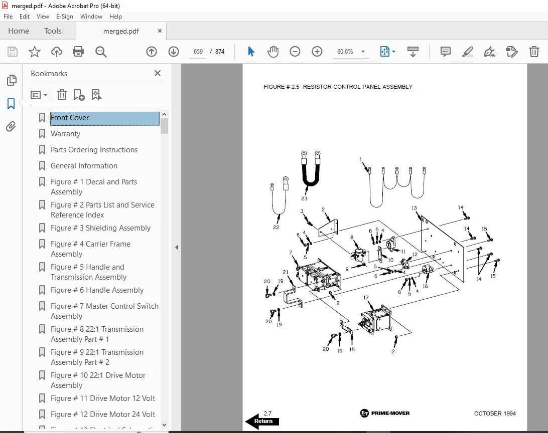
Figure # 2 5 Resistor Control Panel Assembly 659
Figure # 2 6 Resistor Second Speed Contactor Assembly 661
Figure # 2 7 Resistor Forward & Rearward Contactor Assembly 663
Figure # 2 8 Power Connector Assembly 665
Figure # 2 9 Hydraulic Pump Motor Assembly 667
Figure # 2 10 Pump Motor Assembly 669
Figure # 2 11 Drive Motor Assembly, 12 Volt 671
Figure # 2 12 24 Volt Drive Motor Assembly 673
Figure # 2 13 Warning Light Assembly 675
Figure # 2 14 Transistor Electrical Schematic “E” 677
Figure # 2 15 Transistor Electrical Schematic Symbols “E” 678
Figure # 2 16 Transistor Control Wiring Harness “E” 679
Figure # 2 17 Transistor Power Component Wiring “E” 681
Figure # 2 18 Transistor Control Panel Assembly “E” 683
Figure # 2 19 Transistor Forward & Rearward Contactor Assembly 685
Figure # 2 20 Transistor Electrical Schematic “EE” 687
Figure # 2 21 Transistor Electrical Schematic Symbols “EE” 688
Figure # 2 22 Transistor Control Wiring Harness “EE” 689
Figure # 2 23 Transistor Power Component Wiring “EE” 691
Figure # 2 24 Transistor Control Panel Assembly “EE” 693
SN-20 Hydraulic Section 696
Figure # 3 1 SN-20 Two Stage Hydraulic Schematic 697
Figure # 3 2 SN-20 Two Stage Hydraulic Schematic Symbols 698
Figure # 3 3 SN-20 Two Stage Mast Hydraulic System 699
Figure # 3 4 SN-20 Reservoir and Pump Assembly 701
Figure # 3 5 SN-20 Pump and Motor Assembly 703
Figure # 3 6 SN-20 Two Stage Lift Cylinder Assembly 705
Figure # 3 7 SN-20 Three Stage Hydraulic Schematic 707
Figure # 3 8 SN-20 Three Stage Hydraulic Schematic Symbols 708
Figure # 3 9 SN-20 Three Stage Mast Hydraulic System 709
Figure # 3 10 SN-20 Three Stage Freelift Cylinder Assembly 711
Figure # 3 11 SN-20 Three Stage Staging Cylinder Assembly 713
SN-30 Hydraulic Section 716
Figure # 3 12 SN-30 Two Stage Hydraulic Schematic 717
Figure # 3 13 SN-30 Two Stage Hydraulic Schematic Symbols 718
Figure # 3 14 SN-30 Two Stage Mast Hydraulic System, 12 Volt 719
Figure # 3 15 SN-30 Two Stage Mast Hydraulic System, 24 Volt 721
Figure # 3 16 SN-30 Reservoir and Pump Assembly 723
Figure # 3 17 SN-30 Pump and Motor Assembly 725
Figure # 3 18 SN-30 Two Stage Lift Cylinder Assembly 727
Figure # 3 19 SN-30 Two Stage Hydraulic Reservoir Assembly 729
Figure # 3 20 Lift Pump and Motor Assembly 731
Figure # 3 21 Lift Pump Assembly 733
Figure # 3 22 SN-30 Three Stage Hydraulic Schematic 735
Figure # 3 23 SN-30 Three Stage Hydraulic Schematic Symbols 736
Figure # 3 24 SN-30 Three Stage Mast Hydraulic System, 12 Volt 737
Figure # 3 25 SN-30 Three Stage Mast Hydraulic System, 24 Volt Part # I 739
Figure # 3 26 SN-30 Three Stage Mast Hydraulic System, 24 Volt Part # II 741
Figure # 3 27 SN-30 Three Stage Freelift Cylinder Assembly 743
Figure # 3 28 SN-30 Three Stage Staging Cylinder Assembly 745
Figure # 3 29 SN-30 Manual Control Hydraulic Schematic 747
Figure # 3 30 SN-30 Manual Control Hydraulic Schematic Symbols 748
Figure # 3 31 SN-30 Manual Control Hydraulic System – Part # I 749
Figure # 3 32 SN-30 Manual Control Hydraulic System – Part # II 751
Figure # 3 33 SN-30 Manual Lift, Two Stage Lift Cylinder and Related Part 753
Figure # 3 34 SN-30 Manual Lift, Three Stage Lift Cylinder and Related Part 755
Figure # 3 35 Two & Three Spool Control Valve Assembly 757
SN-40 Hydraulic Section 760
Figure # 3 36 SN-40 Two Stage Hydraulic Schematic 761
Figure # 3 37 SN-40 Two Stage Hydraulic Schematic Symbols 762
Figure # 3 38 SN-40 Manual Control Hydraulic System – Part # I 763
Figure # 3 39 SN-40 Manual Control Hydraulic System – Part # II 765
Figure # 3 40 SN-40 Manual Lift, Two Stage Lift Cylinder and Related Part 767
Figure # 3 41 SN-40 Two Stage Cylinder Assembly 769
Figure # 3 42 SN-40 Manual Control Hydraulic Schematic 771
Figure # 3 43 SN-40 Manual Control Hydraulic Schematic Symbols 772
Figure # 3 44 SN-40 Three Stage Hydraulic System – Part # I 773
Figure # 3 45 SN-40 Three Stage Hydraulic System – Part # II 775
Figure # 3 46 SN-40 Three Stage Lift Cylinder and Related Parts 777
Figure # 3 47 SN-40 Three Stage Staging Cylinder Assembly 779
Figure # 3 48 SN-40 Three Stage Freelift Cylinder Assembly 781
Figure # 4 1 Shielding Assembly 783
Figure # 4 2 Main Frame and Load Wheel Installation 785
Figure # 4 3 Spring Loaded Caster Assembly 787
Figure # 4 4 Control Valve Mounting Assembly 789
Figure # 4 5 Pallet Centering Device 791
Figure # 5 1 SN-20/30 Two Stage Mast Installation 793
Figure # 5 2 SN-20/30 Two Stage Mast Outer Column Assembly (Frame) 795
Figure # 5 3 SN-20/30 Two Stage Mast Inner Column Assembly 797
Figure # 5 4 SN-20/30 Two Stage Mast Cylinder and Related Parts 799
Figure # 5 5 SN-20/30 Two Stage Mast Lift Frame and Backrest Assembly 801
Figure # 5 6 SN-20/30 Two Stage Fork Assembly 803
Figure # 5 7 SN-20/30 Three Stage Mast Installation 805
Figure # 5 8 SN-20/30 Three Stage Mast Outer Column Assembly (Frame) 807
Figure # 5 9 SN-20/30 Three Stage Mast Intermediate Column Assembly 809
Figure # 5 10 SN-20/30 Three Stage Mast Inner Column Assembly 811
Figure # 5 11 SN-20/30 Three Stage Mast Freelift Cylinder and Related Parts 813
Figure # 5 12 SN-20/30 Three Stage Mast Lift Frame and Backrest Assembly 815
Figure # 5 13 SN-20/30 Three Stage Fork Assembly 817
Figure # 5 14 SN-40 Two Stage Mast Installation 819
Figure # 5 15 SN-40 Two Stage Mast Outer Column Assembly (Frame) 821
Figure # 5 16 SN-40 Two Stage Mast Inner Column Assembly 823
Figure # 5 17 SN-40 Two Stage Mast Cylinder and Related Parts 825
Figure # 5 18 SN-40 Two Stage Mast Lift Frame and Backrest Assembly 827
Figure # 5 19 SN-40 Two Stage Fork Assembly 829
Figure # 5 20 SN-40 Three Stage Mast Installation 831
Figure # 5 21 SN-40 Three Stage Mast Outer Column Assembly 833
Figure # 5 22 SN-40 Three Stage Mast Intermediate Column Assembly 835
Figure # 5 23 SN-40 Three Stage Mast Inner Column Assembly 837
Figure # 5 24 SN-40 Three Stage Mast Freelift Cylinder Installation 839
Figure # 5 25 SN-40 Three Stage Mast Lift Frame and Load Backrest Assembly 841
Figure # 5 26 SN-40 Three Stage Fork Assembly 843
Figure # 6 1 Hose Reel and Related Parts 844
Figure # 6 2 Dual Elbow Swivel Assembly 846
Figure # 6 3 Hose Reel Assembly 848
Figure # 10 1 Special Tools and Lubrications 850
Numerical Index 853
Back Cover 874
DESCRIPTION:
BT Prime-Mover SN-20 SN-30 SN-40 Electric Walkie Straddle Stacker Parts Manual – PDF DOWNLOAD
300380-000 1986_December
300380-001 1991_February
300380-002 1993_August
300380-003 1994_October
PARTS ORDERING INSTRUCTIONS:
HOW TO ORDER:
- When you order, supply the part number, quantity, model and serial numbers of your machine. Supplying this information will assure prompt, efficient handling of your order. The pictorial reference number is not needed and including it can only add confusion.
- Since your dealer carries many parts in stock and maintains up-to-date prices on all parts, he will be able to process your order immediately. If, for some reason, the part is not in stock, he will order it from the factory. In either event, he maintains a current file of service manuals, which give all available parts ordering or technical information.
- All prices are FOB factory in Muscatine, Iowa. Shipping charges are added to the price of the part shipping from the factory.
WHERE TO ORDER:
Always order parts from the dealer who sold you your Prime-Mover. If it is necessary for the dealer to order parts from the factory, he is able to get prompt service for you. Parts are shipped in accordance with shipping instructions given on the order.
S.V 30/01/2025