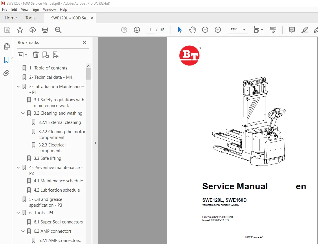
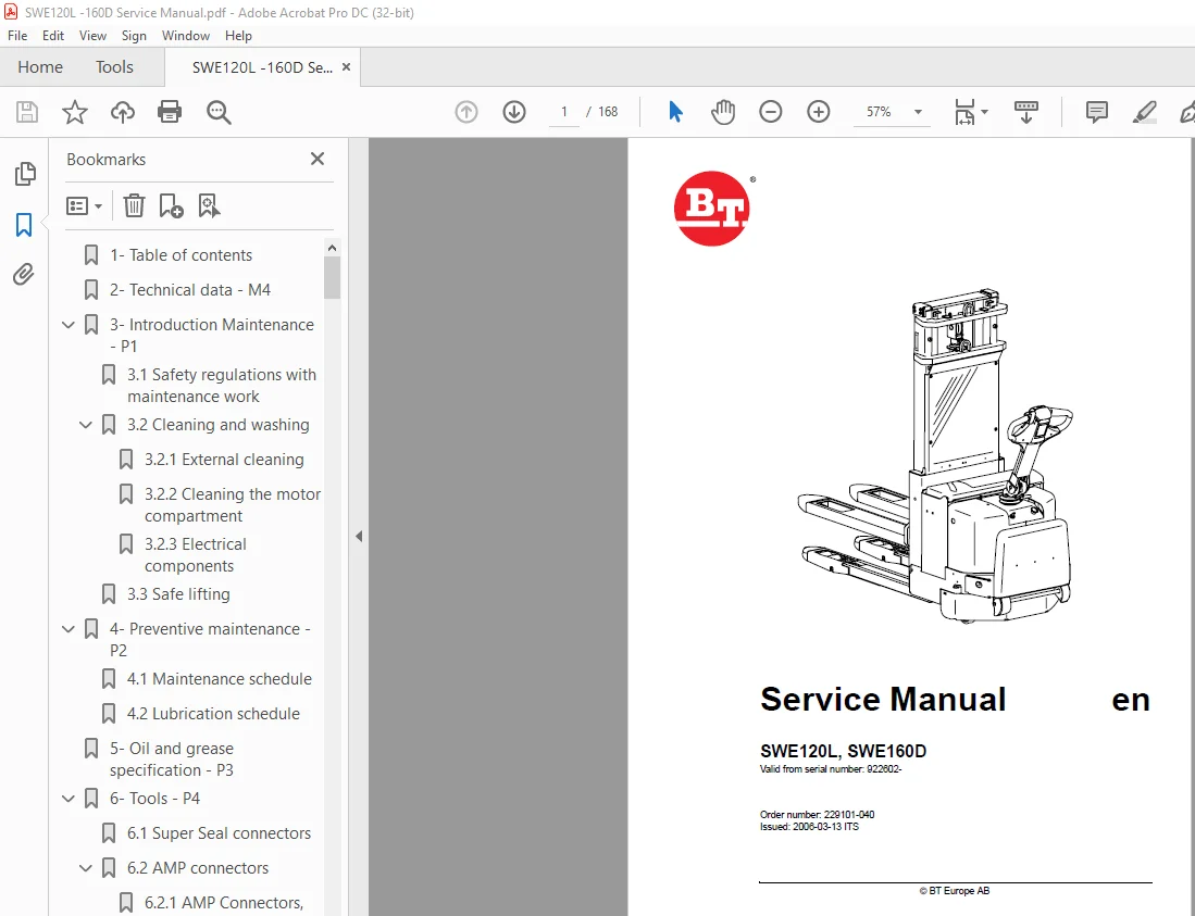
Service Manual BT Toyota Electric Forklift SPE125/160/135S/125L/160L PDF Download
$28.95
BT Toyota Electric Forklift SPE125/160/135S/125L/160L Service Manual – PDF DOWNLOAD
Description
BT Toyota Electric Forklift SPE125/160/135S/125L/160L Service Manual – PDF DOWNLOAD
FILE DETAILS:
BT Toyota Electric Forklift SPE125/160/135S/125L/160L Service Manual – PDF DOWNLOAD
Language : English
Pages :168
Downloadable : Yes
File Type : PDF
TABLE OF CONTENTS:
BT Toyota Electric Forklift SPE125/160/135S/125L/160L Service Manual – PDF DOWNLOAD
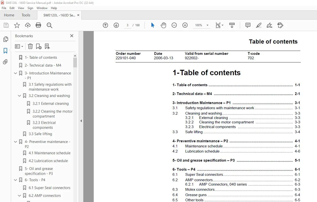
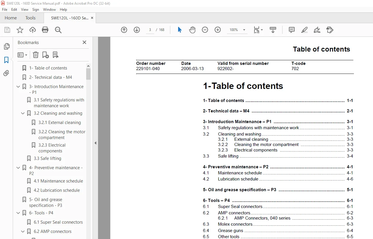
1-Table of contents
1- Table of contents 1-1
2- Technical data – M4 2-1
3- Introduction Maintenance – P1 3-1
31Safety regulations with maintenance work 3-1
32Cleaning and washing 3-3
321 External cleaning 3-3
322 Cleaning the motor compartment 3-3
323 Electrical components 3-3
33Safe lifting 3-4
4- Preventive maintenance – P2 4-1
41Maintenance schedule 4-1
42Lubrication schedule 4-6
5- Oil and grease specification – P3 5-1
6- Tools – P4 6-1
61Super Seal connectors 6-1
62AMP connectors 6-2
621 AMP Connectors, 040 series 6-3
63Molex connectors 6-3
64Grease guns 6-4
65Other tools 6-5
7- Support arms – 0350 7-1
71Greasable support arms 7-1
8- Engine suspension– 0450 8-1
81Component parts 8-1
811 Component List 8-2
812 Adjusting play, turning tube mounting 8-3
9- Electric drive motor – 1760 9-1
91Component parts 9-1
911 Dismantling of motor from truck 9-2
912 Assembling 9-2
92Service/Repairs 9-3
921 Dismantling of motor 9-3
922 Assembling of motor 9-4
923 Cleaning 9-4
10- Drive unit/gear – 2550 10-1
101Component parts 10-2
102Leakage from top cover 10-3
103Changing of the drive shaft’s sealing ring 10-4
1031 Dismantling 10-4
1032 Assembling 10-4
1- 2 Service Manual SWE120L, SWE160D © BT Europe AB
Table of contents
T-code Valid from serial number Date Order number
702 922602- 2006-03-13 229101-040
11- Electro magnetic brake – 3370 11-1
111Main components 11-1
1111 Serial number 570989- 11-1
112Maintenance 11-2
1121 Exchange of brake disc 11-2
12- Steering – 4000 12-1
121Component parts, tiller arm 12-1
122Adjustments 12-2
1221 Adjusting of brake microswitch 12-2
123Tiller arm handle 12-3
1231 Dismantling/Assembling 12-5
Changing of signal button/switch (9, 10) 12-5
Changing of lift/lowering button (13) 12-6
Changing of pushbutton (16) 12-6
13- Electrical systems – 5000 13-1
131General 13-1
1311 Part numbers 13-1
132Component identification 13-2
1321 Component list 13-4
133Electrical wiring diagram 13-6
1331 Symbol list 13-6
1332 Overview 13-7
1333 Electrical wiring diagrams 13-9
134Functional description 13-15
1341 Starting the truck 13-15
1342 Driving 13-15
1343 Neutral speed reduction 13-15
1344 Neutral speed reduction on slopes 13-15
1345 Braking 13-15
1346 Lifting the forks 13-16
1347 Lifting the support arms 13-16
1348 Lowering the forks 13-16
1349 Lowering the support arms 13-16
13410 Horn 13-16
13411 Hour meter 13-16
13412 Transistor regulator 13-17
13413 Spider expansion unit (SEU) (option) 13-17
13414 TLS – Truck log system (optional) 13-20
General 13-20
Registration 13-20
Logging in/out SD16 13-20
Logging in/out S16 13-20
Collision sensor 13-21
Settings 13-21
13415 ID unit (optional) 13-22
General 13-22
Installation 13-22
Settings 13-23
135Parameters 13-25
1351 General 13-25
1352 Viewing parameters – without the CAN service key 13-25
1353 Adjusting operator parameters – without the CAN
11- Electro magnetic brake – 3370 11-1
111Main components 11-1
1111 Serial number 570989- 11-1
112Maintenance 11-2
1121 Exchange of brake disc 11-2
12- Steering – 4000 12-1
121Component parts, tiller arm 12-1
122Adjustments 12-2
1221 Adjusting of brake microswitch 12-2
123Tiller arm handle 12-3
1231 Dismantling/Assembling 12-5
Changing of signal button/switch (9, 10) 12-5
Changing of lift/lowering button (13) 12-6
Changing of pushbutton (16) 12-6
13- Electrical systems – 5000 13-1
131General 13-1
1311 Part numbers 13-1
132Component identification 13-2
1321 Component list 13-4
133Electrical wiring diagram 13-6
1331 Symbol list 13-6
1332 Overview 13-7
1333 Electrical wiring diagrams 13-9
134Functional description 13-15
1341 Starting the truck 13-15
1342 Driving 13-15
1343 Neutral speed reduction 13-15
1344 Neutral speed reduction on slopes 13-15
1345 Braking 13-15
1346 Lifting the forks 13-16
1347 Lifting the support arms 13-16
1348 Lowering the forks 13-16
1349 Lowering the support arms 13-16
13410 Horn 13-16
13411 Hour meter 13-16
13412 Transistor regulator 13-17
13413 Spider expansion unit (SEU) (option) 13-17
13414 TLS – Truck log system (optional) 13-20
General 13-20
Registration 13-20
Logging in/out SD16 13-20
Logging in/out S16 13-20
Collision sensor 13-21
Settings 13-21
13415 ID unit (optional) 13-22
General 13-22
Installation 13-22
Settings 13-23
135Parameters 13-25
1351 General 13-25
1352 Viewing parameters – without the CAN service key 13-25
1353 Adjusting operator parameters – without the CAN
service key 13-26
Table of contents
Order number Date Valid from serial number T-code
229101-040 2006-03-13 922602- 702
© BT Europe AB Service Manual SWE120L, SWE160D 1- 3
1354 Viewing & changing parameters – CAN service key
connected 13-27
Changing a parameter 13-28
1355 Operator parameters 13-29
1356 Parameter description 13-29
Parameter 1 13-29
Parameter 2 13-29
Parameter 3 13-29
Parameter 4 13-29
Parameter 5 13-30
1357 Service parameters 13-31
1358 Parameter description 13-32
Parameter 10 13-32
Parameter 14 13-32
Parameter 15 – Non-configurable options 13-32
Setting Non-configurable options 13-32
Parameter 16 – Configurable option #1 13-33
Parameter 17 – Configurable option #2 13-33
Parameter 18 – Configurable option #3 13-33
Parameter 19 – Configurable option #4 13-33
Parameter 20 13-34
Parameter 21 13-34
Recommendation on parameter setting for freely ventilated batteries 13-35
Instructions for verifying parameter setting 13-36
Recommendation on parameter setting for valve-controlled batteries (VRLA) 13-37
Instructions for verifying parameter setting 13-38
Parameter 22 13-38
Parameter 25 13-38
Parameter 28 13-38
Parameter 39 13-39
Login method and driver parameter access 13-39
Expanded keypad – General 13-39
Expanded keypad – Programming 13-39
1359 Configurable “Option” Parameters 13-42
General 13-42
Summary of base options 13-42
Convention for configurable options 13-43
Detailed option parameter tables 13-45
136Diagnostic and troubleshooting 13-56
1361 General 13-56
1362 Error code history 13-56
1363 Error codes 13-57
1364 Transistor regulator errors 13-69
Resetting errors 13-70
Safety 13-70
1365 Built-in Test Function 13-71
Digital inputs/outputs test mode 13-72
Inputs check 13-72
Outputs check 13-73
Option buttons check 13-74
Display test mode 13-74
137Technical specifications – Curtis 1243 13-75
1- 4 Service Manual SWE120L, SWE160D © BT Europe AB
Table of contents
T-code Valid from serial number Date Order number
702 922602- 2006-03-13 229101-040
14- Hydraulic system – 6000 14-1
141General 14-1
142Hydraulic diagram and components 14-1
1421 Main components 14-2
1422 Description 14-2
Lift 14-2
Lowering 14-2
Operating pressure 14-2
Relief valve 14-3
Pressure switch 14-3
15- Lifting mast – 7000 15-1
151Adjusting the measurement between the guide and the mast 15-1
152Grease the beam flanges and beam ribs 15-2
153Main lift chain system – 15-3
1531 General 15-3
1532 Checking the chain setting 15-3
1533 Chain inspection 15-3
1534 Noise 15-3
1535 Surface rust 15-3
1536 Rusty links 15-3
1537 Stiff links 15-4
1538 Bolt rotation 15-4
1539 Loose bolts 15-4
15310 Outline wear 15-5
15311 Stretching 15-6
15312 Damage 15-6
15313 Damaged discs 15-7
15314 Damaged bolts 15-7
15315 Dirty chain 15-7
15316 Cleaning 15-7
15317 Lubrication 15-7
16- Battery charger (built-in) – 8340 16-1
161General 16-1
162Technical data – charger 16-2
163Charging 16-2
Machine numbers 723984-936512 16-2
Machine numbers 936513- 16-3
164Troubleshooting and service 16-3
165Setting the charger
(applies to machine numbers 723984-936512) 16-4
Freely ventilated batteries 16-4
Valve-regulated batteries 16-4
1651 Current levels at different charger settings (applies to machine numbers 936513-) 16-5
Freely ventilated batteries 16-5
Valve-regulated batteries (Evolution type) 16-6
17- TruckCom 17-1
171General 17-1
172Connection 17-1
173Layout 17-2
1731 Main program screen 17-2
Table of contents
Order number Date Valid from serial number T-code
229101-040 2006-03-13 922602- 702
© BT Europe AB Service Manual SWE120L, SWE160D 1- 5
1732 Nodes 17-2
1733 Icons 17-3
1734 Tool buttons and menu bar 17-3
1735 Information window 17-4
1736 Status bar 17-4
174 Connection function 17-4
175Disconnection function 17-4
176Downloading program function 17-5
1761 Normal downloading (truck with key) 17-5
1762 Normal downloading (truck with keypad) 17-5
1763 Emergency downloading (truck with keypad) 17-6
1764 Emergency downloading (truck with keypad) 17-6
1765 Downloading in old versions of logic card 17-6
177Truck report function 17-7
178Parameters function 17-8
179Diagnostics function 17-8
1791 Representation of signal colours 17-9
1792 “Tiller arm” tab 17-9
1793 “Drive Controller” tab (transistor regulator driving) 17-10
1794 “Pump controller” tab (transistor regulator pump) 17-11
1795 “EPS” (steering servo tab) 17-12
1796 SEU tab (Extra I/O module) 17-13
1710Other menu functions 17-13
17101 Save to file 17-13
17102 Download from file 17-13
17103 Reset CAN adapter 17-14
17104 Delete error code log 17-14
17105 Reset hour meter 17-14
17106 Read error code log 17-14
17107 Adjust date and time 17-14
17108 Adjusting the hour meter on older cards 17-14
17109 Help 17-14
About the TruckCom application 17-14
171010 Exit 17-14
1711Specifications 17-15
1712Installation 17-15
17121 Installation on a PC with Windows® 95/98 17-15
17122 Installation on a PC with Windows XP/2000 17-16
Changes in Windows® Control Panel 17-18
17123 Installation on a PC with Windows NT 17-21
17124 In case of communication problems with CAN 17-21
17125 To uninstall 17-21
IMAGES PREVIEW OF THE MANUAL:
S.M 5/24