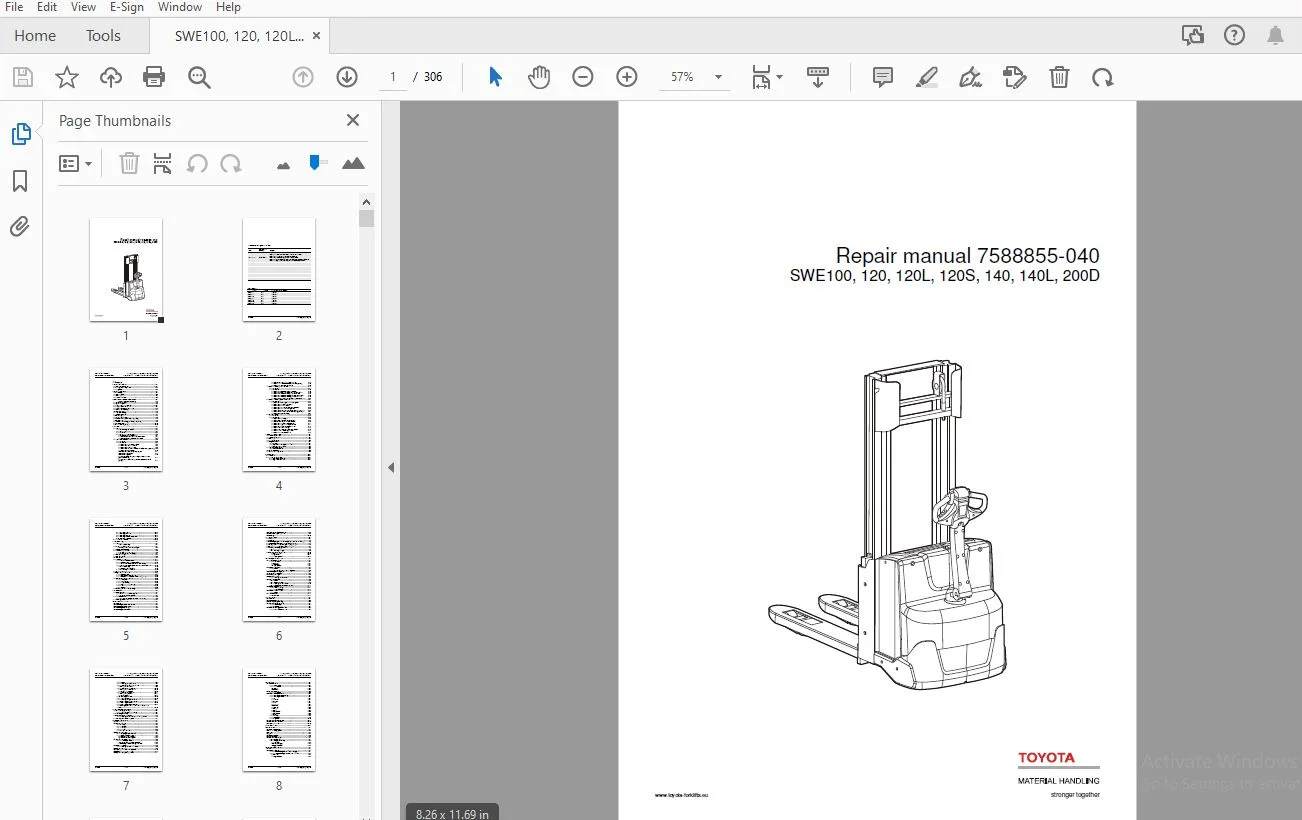
BT TOYOTA SWE100,120,120L,120S,140,140L,200D REPAIR MANUAL 7588855-040 – PDF DOWNLOAD
$28.95
BT TOYOTA SWE100,120,120L,120S,140,140L,200D REPAIR MANUAL 7588855-040 – PDF DOWNLOAD
Description
BT TOYOTA SWE100,120,120L,120S,140,140L,200D REPAIR MANUAL 7588855-040 – PDF DOWNLOAD
FILE DETAILS:
BT TOYOTA SWE100,120,120L,120S,140,140L,200D REPAIR MANUAL 7588855-040 – PDF DOWNLOAD
Language : English
Pages : 306
Downloadable : Yes
File Type : PDF
IMAGES PREVIEW OF THE MANUAL:
TABLE OF CONTENTS:
BT TOYOTA SWE100,120,120L,120S,140,140L,200D REPAIR MANUAL 7588855-040 – PDF DOWNLOAD
1. Contents.......................................................................................0
2. General introduction...........................................................................0
	2.1 How to use this manual....................................................................0
	2.2 Warning levels and symbols................................................................0
	2.3 Pictograms................................................................................0
3. General safety rules...........................................................................0
	3.1 Work safety...............................................................................0
	3.2 Electrical system.........................................................................0
	3.3 Safe lifting..............................................................................0
	3.4 Truck modifications.......................................................................0
4. Operation and connection sequences.............................................................0
	Symbols on keypad and display.................................................................0
	4.1 Battery is connected......................................................................0
	4.2 Login via keypad..........................................................................0
	4.3 Tiller arm lowered for driving............................................................0
	4.4 Driving in fork direction.................................................................0
	4.5 Driving in the drive wheel direction......................................................0
	4.6 Neutral position braking..................................................................0
	4.7 Reverse braking...........................................................................0
	4.8 Mechanical braking........................................................................0
	4.9 Emergency reversal........................................................................0
	4.10 Fork lifting.............................................................................0
	4.11 Fork lifting (SWE100)....................................................................0
	4.12 Support arm lift (SWE120L, 140L, 200D)...................................................0
	4.13 Fork lowering............................................................................0
	4.14 Support arm lowering (SWE120L, 140L, 200D)...............................................0
	4.15 Click-2-Creep............................................................................0
	4.16 Turtle function (option).................................................................0
5. Parameters.....................................................................................0
	5.1 General...................................................................................0
		5.1.1 Show/change parameters..............................................................0
		5.1.2 Operator parameters.................................................................0
		5.1.3 Overview............................................................................0
		5.1.4 Connection to logged-in operator....................................................0
			Description of operator parameters....................................................0
			Parameters 3 and 4 – Acceleration/Deceleration........................................0
			Parameters 6 and 7 – Maximum travel speed.............................................0
	5.2 General service parameters................................................................0
		5.2.1 Overview............................................................................0
		5.2.2 Description.........................................................................0
			Parameter 101/104 – Service/Log-out...................................................0
			Parameter 102 - Operator access.......................................................0
			Parameter 103 - Start-up display......................................................0
			Parameter 105/106 - Collision sensor sensitivity for X/Y (Optional)...................0
			Parameter 107 – Battery size..........................................................0
			Table applicable to LWE140, 160, 180, 200.............................................0
			Table concerning LWE250...............................................................0
			Table concerning SWE..................................................................0
			Verifying parameter settings for freely ventilated batteries (lead-acid batteries)....0
			Verifying the parameter setting for valve-regulated batteries (Exide).................0
			Parameters 109/110 - Built-in charger (option)........................................0
			Parameter 111 - Reset procedure after collision (option)..............................0
			Parameter 112 - Clear application data................................................0
	5.3 Service parameters, travel functions......................................................0
		5.3.1 Overview............................................................................0
		5.3.2 Description.........................................................................0
			Parameter 201 – Deceleration when reversing...........................................0
			Parameter 202 – Maximum speed Turtle mode activated...................................0
			Parameter 203 - Maximum speed, forks above 1.8 m......................................0
			Parameter 204 - Maximum acceleration, forks above 1.8 m...............................0
			Parameter 205 - Maximum reversing, forks above 1.8 m..................................0
			Parameter 206 - Automatic speed reduction, forks above 1.8 m..........................0
	5.4 Service parameters, hydraulic functions...................................................0
		5.4.1 Description.........................................................................0
			Parameter 301 – Ramping value for lowering stop.......................................0
			Parameter 302 - Fork, lowering speed..................................................0
			Parameter 303 - EVP start mode........................................................0
			Parameter 304 - EVP support arm lowering speed........................................0
			Parameter 305 - EVP slow lowering speed...............................................0
			Parameter 306 - Activation of “Click-2-Creep” lifting/lowering........................0
			Parameter 307 - Automatic support arm lowering (On/Off)...............................0
			Parameter 499 - (Not applicable)......................................................0
	5.5 Factory parameters........................................................................0
		5.5.1 Overview............................................................................0
		5.5.2 Description.........................................................................0
			Parameter 1001 - Truck type...........................................................0
			Parameter 1002 - Non-configurable options.............................................0
			Parameters 1003-1042 – Optional functions.............................................0
			Parameter 1044 - Master maximum speed.................................................0
			Parameter 1045 - Type of battery in the truck.........................................0
			Parameter 1046 - Adapting to special trucks...........................................0
			Parameter 1101 - Built-in charger.....................................................0
			Parameter 1102 - Controls for hydraulic function......................................0
			Parameter 1110 – Reset voltage for BDI................................................0
			Parameter 1118 - Hardware version.....................................................0
6. Installation and commissioning.................................................................0
	6.1 Transporting the truck....................................................................0
	6.2 Transporting the mast.....................................................................0
	6.3 Safe lifting..............................................................................0
	6.4 Installing the battery....................................................................0
	6.5 Using PIN codes...........................................................................0
		6.5.1 General.............................................................................0
		6.5.2 PIN code for resetting after a collision............................................0
		6.5.3 Programming PIN codes...............................................................0
	6.6 Programming PIN codes.....................................................................0
		6.6.1 PIN code defaults...................................................................0
	6.7 Setting parameters........................................................................0
	6.8 Function and safety checks................................................................0
7. Maintenance....................................................................................0
	7.1 Introduction..............................................................................0
	7.2 Maintenance instructions..................................................................0
		7.2.1 Cleaning and washing................................................................0
		7.2.2 High-pressure washers...............................................................0
		7.2.3 Degreasing agents...................................................................0
		7.2.4 Cleaning the exterior...............................................................0
		7.2.5 Cleaning the chain..................................................................0
		7.2.6 Cleaning the motor compartment......................................................0
		7.2.7 Electric components.................................................................0
	7.3 Maintenance schedule......................................................................0
8. Troubleshooting................................................................................0
	8.1 General...................................................................................0
		Software compatibility....................................................................0
	8.2 Towing a defective truck..................................................................0
		Tow using a tow truck and tow wagon:......................................................0
	8.3 Emergency driving mode....................................................................0
	8.4 Troubleshooting methods...................................................................0
		8.4.1 General initial troubleshooting.....................................................0
		8.4.2 Concluding troubleshooting..........................................................0
	8.5 Error code history........................................................................0
	8.6 Error code system.........................................................................0
	8.7 Error codes...............................................................................0
	8.8 Troubleshooting chart.....................................................................0
		8.8.1 The truck cannot be driven..........................................................0
		8.8.2 Truck only travels at reduced speed.................................................0
		8.8.3 The truck can be driven but behaves abnormally......................................0
		8.8.4 The truck can be driven, but some functions do not work.............................0
			Software compatibility................................................................0
			Hardware compatibility matrix.........................................................0
		8.8.5 Defective hydraulic functions.......................................................0
	8.9 Built-in test function....................................................................0
	8.10 Digital input/output status..............................................................0
		8.10.1 Test mode “9” –....................................................................0
		8.10.2 Test function “10” – Logic card....................................................0
		8.10.3 Test mode “12” – Expansion unit SEU (option).......................................0
	8.11 Built-in test function for the tiller arm................................................0
		8.11.1 Display test.......................................................................0
		8.11.2 Speed control......................................................................0
		8.11.3 Safety reversing...................................................................0
		8.11.4 Controls for lifting/lowering......................................................0
		8.11.5 Sensilift..........................................................................0
		8.11.6 Keypad.............................................................................0
	8.12 Checking the built-in battery charger....................................................0
9. Chassis 0000...................................................................................0
	9.1 Support arm 0350..........................................................................0
		9.1.1 Support arm lift, lateral adjustment................................................0
		9.1.2 Adjusting the kneeling action.......................................................0
	9.2 Motor mounts 0450.........................................................................0
		9.2.1 Replacing springs (not applicable for SWE120S)......................................0
	9.3 Removing the platform.....................................................................0
10. Electric drive motor 1700.....................................................................0
	10.1 Overview.................................................................................0
	10.2 Removing the motor from the truck........................................................0
	10.3 Removing the toothed wheel...............................................................0
	10.4 Removing motor bearings..................................................................0
	10.5 Removing the RPM sensor..................................................................0
	10.6 Installing the temperature sensor........................................................0
	10.7 Drive motor tightening torques...........................................................0
	10.8 Cleaning.................................................................................0
11. Drive gear 2550...............................................................................0
	11.1 General..................................................................................0
	11.2 Overview.................................................................................0
	11.3 Removing the gear from the truck (not applicable for SWE120S)............................0
	11.4 Removing the drive gear from the truck (SWE120S).........................................0
	11.5 Fitting grease nipples, steering bearings (Option).......................................0
	11.6 Lubrication the steering bearings (Option)...............................................0
	11.7 Checking and changing the oil............................................................0
		11.7.1 Draining oil.......................................................................0
		11.7.2 Checking/refilling oil.............................................................0
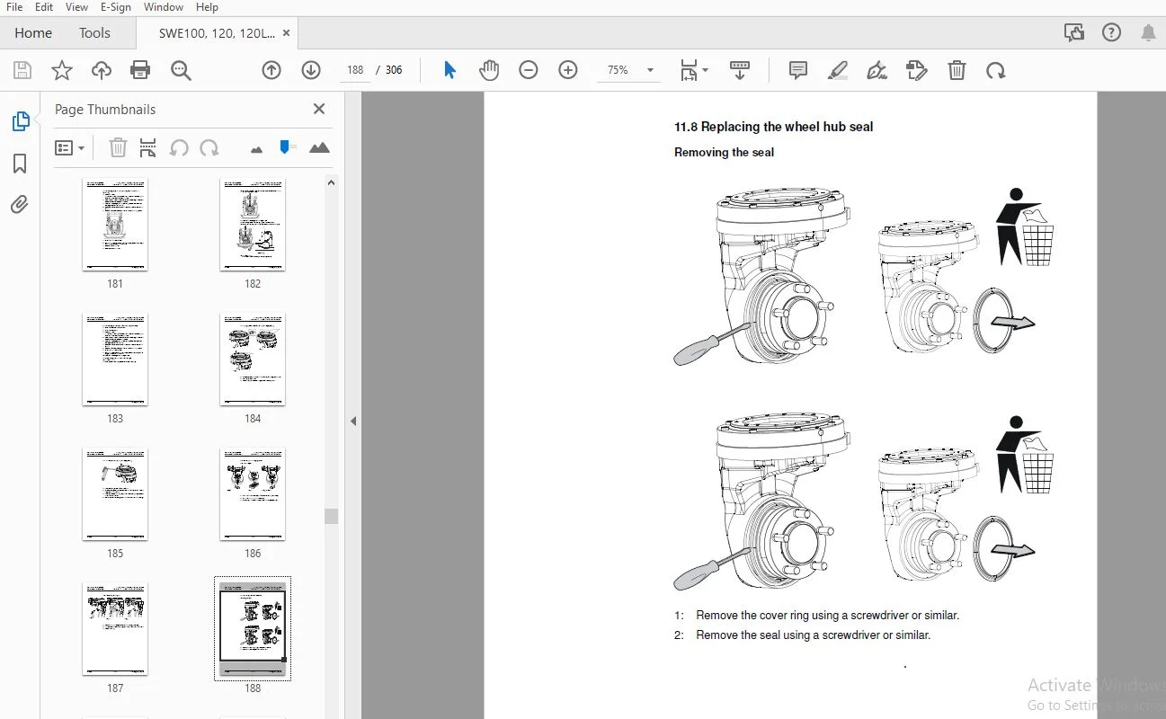
	11.8 Replacing the wheel hub seal.............................................................0
		Removing the seal.........................................................................0
		Fitting the seal..........................................................................0
		11.8.1 Replacing studs....................................................................0
12. Brake system/Wheels C3000.....................................................................0
	12.1 Brake system - C3100.....................................................................0
		12.1.1 Description........................................................................0
			Travel brake..........................................................................0
			Parking brake.........................................................................0
			Emergency brake.......................................................................0
	12.2 Parking brake 3180.......................................................................0
		12.2.1 Overview...........................................................................0
		12.2.2 Emergency release of the parking brake.............................................0
	12.3 Removing the parking brake...............................................................0
	12.4 Fitting the parking brake................................................................0
	12.5 Checking the air gap.....................................................................0
	12.6 Drive wheel 3530.........................................................................0
		12.6.1 Replacing the drive wheel..........................................................0
	12.7 Castor wheels 3540.......................................................................0
		12.7.1 Overview...........................................................................0
		12.7.2 Castor wheel mounting..............................................................0
		12.7.3 Replacing the castor wheel.........................................................0
		12.7.4 Disassembling the castor wheel cradle..............................................0
	12.8 Spring replacement.......................................................................0
		12.8.1 Removing springs...................................................................0
		12.8.2 Fitting the spring.................................................................0
	12.9 Support arm wheel 3550...................................................................0
		12.9.1 Overview...........................................................................0
	12.10 Climber wheels..........................................................................0
		12.10.1 Overview..........................................................................0
13. Tiller arm 4000...............................................................................0
	13.1 Overview.................................................................................0
	13.2 Removing the tiller arm..................................................................0
	13.3 Replacing the gas spring.................................................................0
	13.4 Replacing the safety sensor..............................................................0
		13.4.1 Disassembly........................................................................0
		13.4.2 Assembly...........................................................................0
	13.5 Electrical steering system – 4000........................................................0
		13.5.1 Tiller arm handle C4110............................................................0
		13.5.2 Overview...........................................................................0
		13.5.3 Replacing the keypad C9420.........................................................0
		13.5.4 Replacing the upper cover C4110....................................................0
			Removing the upper cover..............................................................0
		13.5.5 Replacing the tiller arm handle....................................................0
			Removing the tiller arm handle........................................................0
			Fitting the tiller arm handle.........................................................0
		13.5.6 Replacing the logic card...........................................................0
			Removing the logic card...............................................................0
			Fitting the logic card................................................................0
		13.5.7 Checking the handle................................................................0
		13.5.8 Update the software................................................................0
		13.5.9 Replacing the signal button/switch.................................................0
		13.5.10 Replacing the lift/lower button...................................................0
		13.5.11 Replacing the sensilift...........................................................0
		13.5.12 Replacing the stomach button......................................................0
		13.5.13 Changing the position of the controls - support arm lift/ fork lift...............0
14. Electrical components-5000....................................................................0
	14.1 Li-ion battery (Hoppecke)................................................................0
		14.1.1 Resetting/restarting the battery...................................................0
	14.2 Inspecting the battery...................................................................0
	14.3 Replacing the wiring harness.............................................................0
		14.3.1 Replacing the transistor regulator wiring harness..................................0
	14.4 Replacing the transistor regulator.......................................................0
15. Hydraulic system 6000.........................................................................0
	15.1 General..................................................................................0
	15.2 Hydraulic hygiene........................................................................0
		15.2.1 Washing............................................................................0
		15.2.2 Packaging..........................................................................0
		15.2.3 Handling...........................................................................0
		15.2.4 Storage............................................................................0
		15.2.5 Work procedures....................................................................0
	15.3 Hydraulic unit 6100......................................................................0
		15.3.1 Emptying the hydraulic tank........................................................0
		15.3.2 Hydraulic system, bleeding.........................................................0
			Cylinders with bleeding valve.........................................................0
			Cylinders without bleeding valve......................................................0
	15.4 Hydraulic connections 6230...............................................................0
		15.4.1 Quick change connectors............................................................0
			Connecting the quick change connector.................................................0
			Disassembly of the quick change connector.............................................0
	15.5 Hose rupture valve.......................................................................0
		15.5.1 Replacing the hose rupture valve...................................................0
	15.6 Hydraulic calibration....................................................................0
	15.7 Adjusting the pressure limiting valve....................................................0
	15.8 Disassembling the hydraulic unit.........................................................0
	15.9 Hydraulic unit tightening torques........................................................0
16. Mast C7000....................................................................................0
	16.1 Main mast 7100...........................................................................0
		16.1.1 Components.........................................................................0
		16.1.2 Maintenance........................................................................0
			Fixing point..........................................................................0
			Lubrication...........................................................................0
	16.2 Fork carriage 7420.......................................................................0
		16.2.1 Maintenance........................................................................0
	16.3 Main lift chain system 7120..............................................................0
		16.3.1 Checking the chain setting.........................................................0
		16.3.2 Checking the chain.................................................................0
			Noise.................................................................................0
			Surface rust..........................................................................0
			Rusty links...........................................................................0
			Stiff links...........................................................................0
			Bolt rotation.........................................................................0
			Loose bolts...........................................................................0
			Outline wear..........................................................................0
			Stretching............................................................................0
			Damage................................................................................0
			Damaged plates........................................................................0
			Damaged bolts.........................................................................0
			Dirty chain...........................................................................0
		16.3.3 Cleaning...........................................................................0
		16.3.4 Lubrication........................................................................0
		16.3.5 Adjustment.........................................................................0
	16.4 Replacing the fork carriage..............................................................0
	16.5 Replacement of the mast..................................................................0
	16.6 Adjusting the mast.......................................................................0
17. Peripherals C8000.............................................................................0
18. Accessories...................................................................................0
	18.1 Spider expansion unit....................................................................0
	18.2 TLS - Truck log system...................................................................0
	18.3 ID unit..................................................................................0
	18.4 I_Site...................................................................................0
	18.5 DC/DC converter..........................................................................0
	18.6 Collision sensor.........................................................................0
	18.7 Built-in battery charger.................................................................0
		18.7.1 Technical data.....................................................................0
		18.7.2 Charging the battery...............................................................0
			Main charging.........................................................................0
			Equalising charging...................................................................0
			Charging completed....................................................................0
19. Instructions for disposal.....................................................................0
	19.1 General..................................................................................0
	19.2 Marking of plastics......................................................................0
		19.2.1 General marking of products and packaging..........................................0
		19.2.2 Marking according to the manufacturer’s standards..................................0
			Abbreviations.........................................................................0
			Marking examples......................................................................0
	19.3 Pressure vessels.........................................................................0
		19.3.1 Gas struts.........................................................................0
	19.4 Sorting categories.......................................................................0
20. Electrical components and wiring diagrams.....................................................0
	20.1 Electric components......................................................................0
	20.2 Wiring diagram...........................................................................0
		20.2.1 List of symbols....................................................................0
		20.2.2 General wiring diagram.............................................................0
		20.2.3 Wiring diagram.....................................................................0
21. Hydraulics chart..............................................................................0
22. Tools.........................................................................................0
	22.1 MQS contacts.............................................................................0
	22.2 AMP connectors...........................................................................0
		22.2.1 AMP connectors, Multilock series 040...............................................0
	22.3 Molex connectors.........................................................................0
	22.4 Grease guns..............................................................................0
	22.5 Other tools..............................................................................0
23. Oil and grease specification..................................................................0
	23.1 General tightening torques...............................................................0
	23.2 Oil and grease specification.............................................................0
DESCRIPTION:
BT TOYOTA SWE100,120,120L,120S,140,140L,200D REPAIR MANUAL 7588855-040 – PDF DOWNLOAD
How to use this manual
The repair manual is divided into chapters containing the following information:
• General safety rules.
• Operation and connection sequences – This chapter provides a basic description of the main functions of the truck and their interdependencies.
• Parameters – This chapter provides a basic description of the truck parameters.
• Installation – This chapter describes the preparatory work that is to be done before the truck is used for the first time.
• Maintenance – This chapter provides an overview of periodic maintenance.
• Troubleshooting – This chapter describes the action you should take when the truck is completely or partially malfunctioning. It also describes the cause of the problem together with suggested remedies.
• C codes – This chapter describes the various truck systems, e.g. the hydraulic system and includes descriptions of system parts and the necessary service procedures. These descriptions are divided according to TMHMS’s C code system.
• Instructions for disposal – This chapter specifies the proper sorting categories for the materials used in the various truck components.
• Wiring diagram – This chapter provides information on electrical components and wiring diagrams.
• Hydraulic diagram – This chapter provides information on hydraulic components and hydraulic diagrams.
• Tools – This chapter provides a list of the special tools required.
• Service data and grease specifications – This chapter contains information on general tightening torques and an oil and grease specification.
• Technical data.
S.S 06/01/2025