Bucyrus 30MB3 Maintenance Manual- CAT Continuous Miner 30MB3 – PDF DOWNLOAD
Original price was: $80.00.$34.95Current price is: $34.95.
CAT Continuous Miner 30MB3 – 30MB3 – BI620137 – M01404 – Leighton Contractors 1 Operation & Maintenance Manuals EN PDF
Description
Bucyrus 30MB3 Maintenance Manual- CAT Continuous Miner 30MB3 – PDF DOWNLOAD
DESCRIPTION:
Bucyrus 30MB3 Maintenance Manual- CAT Continuous Miner 30MB3 – PDF DOWNLOAD
General
- The 30MB3 miner is a radio-controlled drum-type continuous miner with appropriate weight balance, cutting and loading power to enable the productive mining of coal and other soft mineral in seams ranging from 1,900mm up to 4, 000mm thick.
- The machine is mounted on crawler tracks that provide full mobility and sharp turning radius in both bord and pillar and long wall development mining plans.
- The ranging cutting head mines material from the solid face using a chainless rotating drum, and a CLA-type gathering head with high speed conveyor efficiently moves mined material to a haulage system behind the miner.
- The machine’s weight and balance is designed to mine most efficiently by either sumping into the face at the top or bottom of the seam, and ripping material to the bottom or top of the seam.
- The above figure shows a general arrangement of major mechanical components. A full description of the various major sub-systems of the 30MB3 follows
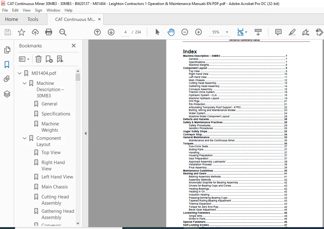
TABLE OF CONTENTS:
Bucyrus 30MB3 Maintenance Manual- CAT Continuous Miner 30MB3 – PDF DOWNLOAD
Machine Description – 30MB3 7
General 7
Specifications 7
Machine Weights 8
Component Layout 9
Top View 9
Right Hand View 10
Left Hand View 11
Main Chassis 12
Cutting Head Assembly 12
Gathering Head Assembly 14
Conveyor Assembly 15
Traction Drive System 16
Hydraulic System – CLA 18
Machine Hydraulic Layout 19
Drill Rigs 21
Rib Protection 21
Articulating Temporary Roof Support – ATRS 22
Bolting, Mining and Maintenance Modes 23
Water System 24
Machine Water Component Layout 26
Defects and Hazards 28
Safety & Maintenance Practices 28
Safety Procedures 28
Isolation Procedures 29
Auger Safety Stops 32
Conveyor Stop 34
General Maintenance 35
Maintenance and the Continuous Miner 35
Torques 36
Duo-Cone Seals 37
Mating Pairs 37
Handling 37
Housing Preparation 37
Seal Preparation 37
Approved Assembly Lubricants* 38
Installation Process 38
Final Assembly 38
Maintenance Guidelines 39
Bearing and Gears 41
Bearing Assembly Methods 41
Assembly Methods 42
Micronized Graphite for Bearing Assembly 42
Drivers for Bearing Cups and Cones 42
Heating Bearings 42
Heating in Oil 42
Induction Heating 43
Freezing/Shrinking Bearing Cups 43
Tapered Rolling Bearing Adjustment 43
Thermal Expansion 43
Torque for Zero End Play 44
Bevel Gear Adjustment 45
Lockwiring Fasteners 46
Single Wire 46
Wired In Pairs 46
Special Fasteners 46
Self-Locking Screws 47
Installation Recommendations 47
Locknuts 48
Installation Recommendations 48
Component Substitution 48
Safety Maintenance 49
General Description 49
Removal of Cutting Drums 52
Pull In Drum Removal 53
Pull In Drum Assembly 55
Drive Drum Removal 56
Drive Drum Assembly 58
Intermediate Drum Removal RH and LH 60
Removal of Pull In Assembly Complete 61
Intermediate Drum Removal LH 64
Intermediate Drum Assembly RH and LH 68
Install Complete Pull In Assembly 69
Centre Drum Removal 72
Centre Drum Assembly 74
Removal of Cutting Motor Clutches 76
Clutch Assembly 79
Removal of Cutter Head Gear Case 80
Reinstall Cutter Head Gear Case 84
Removal of Cutter Motor 86
Installation of Cutter Motor 88
Removal of the Cutter Head Input Gear Case 90
Installation of Cutter Head Input Gear Case 91
Removal of the Cutting Head Support from the Main Frame 92
Installation of Cutting Head Assembly to the Main Frame 96
GATHERING HEAD ASSEMBLY 98
General Description 98
Removal and Replacing Gathering Head Shear Shaft 99
Conveyor Chain Disassembly 102
Removal of Foot Shaft and Centrifugal Loading Arms (CLAs) 104
Removing the Centrifugal Loading Arms (CLAs) 105
Re-Fitting the Centrifugal Loading Arms (CLAs) 107
Removal of the Drive Motor Input Gear Case and CLA Pot 108
Reassembly of Gathering Head Gear Cases 112
Removal of the Gathering Head from the Main Frame 114
Installation of the Gathering Head 120
CONVEYOR ASSEMBLY 123
General Description 123
Conveyor Chain Removal 124
Conveyor Chain Installation 126
Removal of the Conveyor Assembly from the Miner 128
Installation of the Conveyor Assembly 132
Removal of Discharge Conveyor 133
Installation of Discharge Conveyor 136
Removal of Tail Roller 137
Re-Fitting of Tail Roller 139
TRACTION SYSTEM 140
General Description 140
Removal of the Tram Drive Gear Case Assembly 141
Installation of the Tram Drive Gear Case Assembly 145
Removal of a Tram Drive Motor 148
Installation of a Tram Motor 150
Crawler Chain Removal 151
Crawler Chain Installation 155
Crawler Take-Up Roller Removal 158
Crawler Take-Up Roller Installation 159
Stablising Shoe Assembly 160
Stabiliser Cylinder Removal 160
Stabiliser Cylinder Installation 162
Stabiliser Shoe Removal 163
Cutterhead Raise and Lower Cylinder 165
Cutter Head Cylinder Removal 166
Cutter Head Cylinder Installation 167
Gathering Head Raise and Lower Cylinder 168
Gathering Head Cylinder Removal 169
Gathering Head Cylinder Installation 170
Conveyor Raise and Lower Cylinder 171
Conveyor Raise Cylinder Removal 172
Conveyor Raise Cylinder Installation 173
Conveyor Swing Cylinder 175
Conveyor Swing Cylinder Removal 176
Conveyor Swing Cylinder Installation 177
Plow Cylinders 178
Plow Cylinder Removal 179
Plow Cylinder Installation 180
Conveyor Take-Up Cylinders 181
Conveyor Take-up Cylinder Removal 182
Conveyor Take-up Cylinder Installation 183
TRS Raise and Lower Cylinder 184
TRS Cylinder Removal 185
Servicing and Maintenance 187
Top View Lubrication 188
Left Hand Side Lubrication 189
Right Hand Side Lubrication 190
Lubrication Chart 191
Lubrication – Gear Oil 192
Tram Gear Cases 192
Gathering Head (POT) Gear Cases 195
Gathering Head Input Gear Cases 196
Traction Idler Roller 197
Greasing 198
Tram Brakes 198
Filters 198
Left Hand Filters 198
Right Hand Filters 198
Right Hand Filters 199
Chain Adjustments 200
Crawler Track Chain Adjustment 200
Conveyor Chain Adjustment 201
Maintenance Mode 203
Check and Fill Hydraulic Oil Reservoir 203
Hydraulic Oil Power Fill 204
Gear Case Oil Power Fill 206
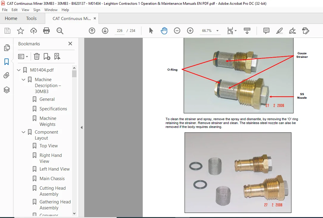
Repair or Replace Water Sprays 207
Machine Cutting Picks 208
HYDRAULIC COMPONENTS ASSEMBLY 209
Description 209
Mechanical 210
Hydraulic Pump Removal 210
Hydraulic Pump Installation 213
Removal and Replacement of Pump Drive Motor 215
Pump Drive Motor Removal 216
Pump Drive Motor Installation 217
Hydraulics 218
Hydraulic Pump 220
Power Cut Off Control – D 221
Load Sensing Control – S 221
Valve Bank Information 221
Adjustments 222
Pilot Circuit 222
Conveyor Tension and Tramming Brake Coolant 222
Main Relief Valve (Main valve bank inlet) – OPTIONAL 222
Water Reticulation 222
General 222
Circuit 1 (Right Side) 223
Circuit 2 (Left Side) 223
Water Dust Spray 223
Tramming 224
Water Sprays 224
Flow Switches 226
Pumps 226
Traction 227
Cutters 228
Conveyor 228
Event Monitor 229
Fault Log inside Event Monitor 230
Main Control Case Indicators 231
Water Troubleshooting Guide 232
Service 233
BUCYRUS 30MB3 MAINTENANCE MANUAL- CAT CONTINUOUS MINER 30MB3 – PDF DOWNLOAD:
IMAGES PREVIEW OF THE MANUAL:


PLEASE NOTE:
- This is the SAME manual used by the dealers to troubleshoot any faults in your vehicle. This can be yours in 2 minutes after the payment is made.
- Contact us at [email protected] should you have any queries before your purchase or that you need any other service / repair / parts operators manual.
S.M