Caterpillar 3024C Engine For Caterpillar Built Machine Service Repair Manual – PDF Download
Original price was: $34.95.$21.95Current price is: $21.95.
Caterpillar 3024C Engine For Caterpillar Built Machine Service Repair Manual
Description
Caterpillar 3024C Engine For Caterpillar Built Machine Service Repair Manual
FILE DETAILS:
FILE TYPE:PDF
DOWNLOADABLE:YES
MANUAL LANGUAGE:ENGLISH
NUMBER OF PAGES:276 pages
SIZE:7.08 MB
DESCRIPTION:
Care must be taken to ensure that fluids are contained during performance of inspection, maintenance, testing, adjusting and repair of the product. Be prepared to collect the fluid with suitable containers before opening any compartment or disassembling any component containing fluids. Refer to Special Publication, NENG2500, “Caterpillar Tools and Shop Products Guide” for tools and supplies suitable to collect and contain fluids on Caterpillar products. Dispose of all fluids according to local regulations and mandates.
TABLE OF CONTENTS:
- Caterpillar 3024C Engine For Caterpillar Built Machine Service Repair Manual
Specifications
INDEX 1 1
Engine Design 3 3
Fuel Injection Lines 4 4
Fuel Injection Pump 5 5
Fuel Injection Nozzles 6 6
Fuel Transfer Pump 7 7
Rocker Shaft 8 8
Valve Mechanism Cover 9 9
Cylinder Head Valves 10 10
Cylinder Head 13 13
Exhaust Manifold 15 15
Camshaft 16 16
Camshaft Lobe Lift
Retainer Plate for the Camshaft
Engine Oil Lines 18 18
Engine Oil Filter 19 19
Engine Oil Relief Valve 20 20
Engine Oil Pump 21 21
Engine Oil Pressure 23 23
Engine Oil Pan 24 24
Oil Suction Tube and Oil Strainer
Water Temperature Regulator 25 25
Water Temperature Regulator Housing
Cylinder Block 26 26
Crankshaft 27 27
Measure Wear on the Crankshaft
Measure the Main Bearing Clearance
Crankshaft Main Bearing Cap
Connecting Rod Bearing Journal 30 30
Main Bearing Journal 31 31
Connecting Rod 32 32
Markings on the Connecting Rod
Distortion of the Connecting Rod
Piston and Rings 34 34
Markings on the Piston
Piston Rings
Pistons
Housing (Front) 36 36
Gear Group (Front) 37 37
Flywheel 38 38
Flywheel Housing 39 39
Crankshaft Pulley 40 40
Belt Tension Chart 41 41
Fan Drive 42 42
Engine Lifting Bracket 43 43
Alternator and Regulator 44 44
Electric Starting Motor 45 45
Starting Motor
Start Relays
Coolant Temperature Switch 47 47
Engine Oil Pressure Switch 48 48
Glow Plugs 49 49
Fuel Shutoff Solenoid 50 50
SENR5005-03
Systems Operation
INDEX 1 51
Engine Design 5 55
3024C Engine
General Information 6 56
Engine Description
Lifting the Engine
3024C Engine Model Views
Fuel System 8 58
General Operation of the Fuel System
Governor
Fuel Injection Pump
Fuel Injection Nozzles
Fuel Transfer Pump
Glow Plugs
Air Inlet and Exhaust System 13 63
Cylinder Head And Valves
Lubrication System 15 65
Cooling System 17 67
Basic Engine 18 68
Cylinder Head and Block
Pistons and Connecting Rods
Timing Gear Case and Gears
Electrical System 20 70
Engine Electrical System
Automatic Shutdown System
Automatic Shutdown Conditions
Charging System Components
Alternator
Regulator
Starting System Components
Solenoid
Electric Starting Motor
Other Components
Circuit Breaker
SENR5005-03
Testing and Adjusting
Troubleshooting 25 75
Introduction
Troubleshooting The Fuel Injection Nozzles On The Engine
The engine is difficult to start or the engine runs rough.
The engine exhaust has too much black smoke.
The engine has lost power and the engine uses too much fuel.
The engine is misfiring, running rough, or running poorly.
Troubleshooting Fuel Injection Nozzles on a Nozzle Tester
Back leakage
The fuel injection nozzle does not inject fuel in the correct quantity or in the correct pattern.
Troubleshooting the Engine
The engine will not start.
The engine starts and the engine runs for a brief period of time and the engine stops.
The engine misfires or the engine runs rough.
The engine runs evenly, but the engine loses power.
The engine lacks power.
The engine has excessive vibration.
The engine has excessive combustion noise.
The engine has excessive valve compartment noise.
Engine oil is in the cooling system.
Engine knock occurs.
The rocker arm has insufficient movement and the valve lash exceeds the specification.
A cylinder head valve is loose.
Oil condenses at the exhaust.
The valve lash is less than the required specification.
Engine components have early wear.
Coolant is in the engine oil.
The engine exhaust has too much black smoke or too much gray smoke.
The engine exhaust has too much white smoke or too much blue smoke.
The engine has low oil pressure.
The engine oil pressure is too high.
The engine uses too much engine oil.
The engine overheats.
The exhaust temperature is too high.
The starting motor does not turn or the starting motor turns too slowly.
The starting motor turns, but the pinion gear does not engage the flywheel ring gear.
The engine does not crank or the engine rotates slowly when the keyswitch is in the start position.
The starting motor continues to run after the ignition switch is released.
The pinion gear does not disengage after the engine starts to run.
The alternator does not charge the battery or the alternator charge rate is slow or irregular.
The alternator charges the battery to a voltage that is too high.
The alternator is noisy.
Fuel System – Inspect 40 90
Air in Fuel – Test 41 91
Engine Speed – Check 43 93
Finding Top Center Position for No. 1 Piston 44 94
Fuel Injection Nozzle – Test 46 96
Inspection and Cleaning of the Fuel Injection Nozzles
Leakage Test
Pressure Test
Test for the Nozzle Spray Pattern
Fuel Injection Timing – Check 50 100
Fuel Quality – Test 51 101
Fuel System – Prime 52 102
Fuel System Pressure – Test 54 104
Gear Group (Front) – Time 56 106
Air Inlet and Exhaust System – Inspect 57 107
Exhaust Temperature – Test 58 108
Measure the Exhaust Temperature
Engine Crankcase Pressure (Blowby) – Test 59 109
Compression – Test 60 110
Compression
Engine Valve Lash – Inspect/Adjust 62 112
Valve Lash Check
Valve Lash Adjustment
Valve Depth – Inspect 65 115
Valve Guide – Inspect 66 116
Engine Oil Pressure – Test 67 117
Engine Oil Pump – Inspect 68 118
Excessive Bearing Wear – Inspect 70 120
Excessive Engine Oil Consumption – Inspect 71 121
Engine Oil Leaks on the Outside of the Engine
Engine Oil Leaks into the Combustion Area of the Cylinders
Cooling System – Check – Overheating 72 122
Cooling System – Inspect 74 124
Cooling System – Test 75 125
Test Tools For The Cooling System
Making the Correct Antifreeze Mixtures
Checking the Filler Cap
Testing The Radiator And Cooling System For Leaks
Cooling System Conditioner
Water Temperature Regulator – Test 81 131
Water Pump – Inspect 82 132
Piston Ring Groove – Inspect 83 133
Inspect the Piston and the Piston Rings
Inspect the Clearance of the Piston Ring
Inspect the Piston Ring End Gap
Connecting Rod – Inspect 85 135
Distortion of Connecting Rod
Inspect the Bearings and Piston Pin for Wear
Connecting Rod Bearings – Inspect 87 137
Main Bearings – Inspect 88 138
Cylinder Block – Inspect 89 139
Cylinder Head – Inspect 90 140
Piston Height – Inspect 92 142
Flywheel – Inspect 94 144
Alignment of the Flywheel Face
Flywheel Runout
Flywheel Housing – Inspect 95 145
Face Runout (Axial Eccentricity) of the Flywheel Housing
Bore Runout (Radial Eccentricity) of the Flywheel Housing
Gear Group – Inspect 97 147
Alternator – Test 98 148
Battery – Test 99 149
Charging System – Test 100 150
Alternator Regulator
Coolant Temperature Switch – Test 101 151
Electric Starting System – Test 102 152
Engine Oil Pressure Switch – Test 103 153
Fuel Shutoff Solenoid – Test 104 154
Glow Plugs – Test 105 155
Continuity Test
Glow Plug Circuit
SENR5006-04
Disassembly and Assembly
INDEX 1 157
Fuel Transfer Pump – Remove 5 161
Removal Procedure
Fuel Transfer Pump – Install 6 162
Installation Procedure
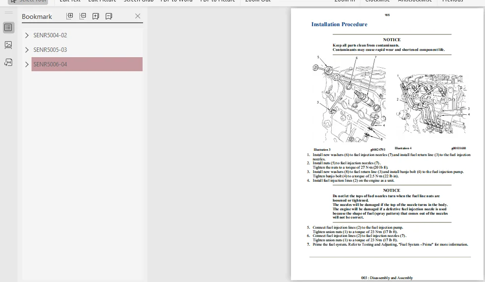
Fuel Injection Lines – Remove and Install 7 163
Removal Procedure
Installation Procedure
Fuel Injection Nozzles – Remove 10 166
Removal Procedure
Fuel Injection Nozzles – Install 11 167
Installation Procedure
Fuel Shutoff Solenoid – Remove and Install 12 168
Removal Procedure
Installation Procedure
Governor – Disassemble 14 170
Disassembly Procedure
Removal of the Governor Weight Assembly
Removal of the lever for the Engine Stop
Remove the linkage for the fuel injection pump
Remove the Speed Control Lever for the Engine
Governor – Assemble 17 173
Assembly Procedure
Install the Speed Control Lever for the Engine
Install the Linkage for the Fuel Injection Pump
Installation of the Lever for the Engine Stop
Installation of the Governor Weight Assembly
Fuel Injection Pump – Remove 20 176
Removal Procedure
Fuel Injection Pump – Install 21 177
Installation Procedure
Exhaust Manifold – Remove and Install 22 178
Removal Procedure
Installation Procedure
Inlet and Exhaust Valve Springs – Remove and Install 24 180
Removal Procedure
Installation Procedure
Inlet and Exhaust Valves – Remove and Install 27 183
Removal Procedure
Removal Procedure (Alternate Method)
Installation Procedure
Installation Procedure (Alternate Method)
Engine Oil Line – Remove and Install 30 186
Removal Procedure
Installation Procedure
Engine Oil Relief Valve – Remove and Install 31 187
Removal Procedure
Installation Procedure
Engine Oil Pump – Remove 33 189
Removal Procedure
Engine Oil Pump
Idler Hub
Engine Oil Pump – Install 36 192
Installation Procedure
Idler Hub
Engine Oil Pump
Water Pump – Remove 39 195
Removal Procedure
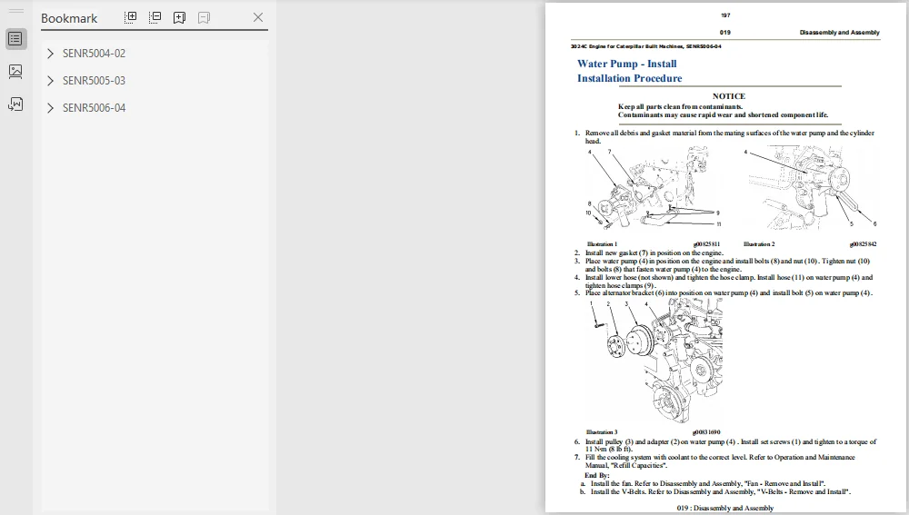
Water Pump – Install 41 197
Installation Procedure
Water Temperature Regulator – Remove and Install 42 198
Removal Procedure
Installation Procedure
Flywheel – Remove 44 200
Removal Procedure
Flywheel – Install 46 202
Installation Procedure
Crankshaft Rear Seal – Remove 48 204
Removal Procedure
Crankshaft Rear Seal – Install 49 205
Installation Procedure
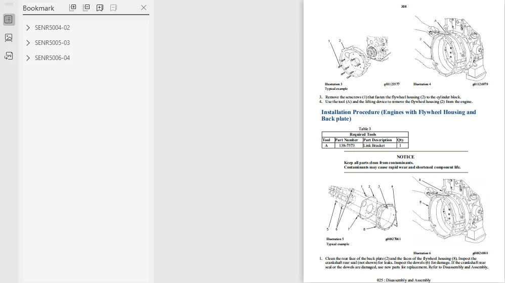
Flywheel Housing – Remove and Install 50 206
Removal Procedure (Engines with Flywheel Housing and Back plate)
Removal Procedure (Engines with Flywheel Housing)
Installation Procedure (Engines with Flywheel Housing and Back plate)
Installation Procedure (Engines with Flywheel Housing)
Crankshaft Pulley – Remove and Install 55 211
Removal Procedure
Installation Procedure
Crankshaft Front Seal – Remove 57 213
Removal Procedure
Crankshaft Front Seal – Install 58 214
Installation Procedure
Housing (Front) – Remove 59 215
Removal Procedure
Housing (Front) – Install 61 217
Installation Procedure
Crankcase Breather – Remove and Install 62 218
Removal Procedure
Installation Procedure
Valve Mechanism Cover – Remove and Install 64 220
Removal Procedure
Installation Procedure
Rocker Shaft and Pushrod – Remove 66 222
Removal Procedure
Rocker Shaft – Disassemble 68 224
Disassembly Procedure
Rocker Shaft – Assemble 69 225
Assembly Procedure
Rocker Shaft and Pushrod – Install 70 226
Installation Procedure
Cylinder Head – Remove 71 227
Removal Procedure
Cylinder Head – Install 73 229
Installation Procedure
Lifter Group – Remove and Install 75 231
Removal Procedure
Installation Procedure
Camshaft – Remove 77 233
Removal Procedure
Camshaft – Install 79 235
Installation Procedure
Engine Oil Pan – Remove and Install 81 237
Removal Procedure
Installation Procedure
Pistons and Connecting Rods – Remove 83 239
Removal Procedure
Pistons and Connecting Rods – Disassemble 84 240
Disassembly Procedure
Pistons and Connecting Rods – Assemble 86 242
Assembly Procedure
Pistons and Connecting Rods – Install 88 244
Installation Procedure
Connecting Rod Bearings – Remove 90 246
Removal Procedure
Connecting Rod Bearings – Install 91 247
Installation Procedure
Crankshaft Main Bearings – Remove 93 249
Removal Procedure
Crankshaft Main Bearings
Crankshaft Bearing (Front)
Crankshaft Main Bearings – Install 95 251
Installation Procedure
Crankshaft Main Bearings
Crankshaft Bearing (Front)
Crankshaft – Remove 97 253
Removal Procedure
Crankshaft – Install 98 254
Installation Procedure
Bearing Clearance – Check 99 255
Measurement Procedure
Coolant Temperature Switch – Remove and Install 101 257
Removal Procedure
Installation Procedure
Engine Oil Pressure Switch – Remove and Install 103 259
Removal Procedure
Installation Procedure
Glow Plugs – Remove and Install 105 261
Removal Procedure
Installation Procedure
V-Belts – Remove and Install 107 263
Removal Procedure
Installation Procedure
Alternator – Remove and Install 109 265
Removal Procedure
Installation Procedure
Electric Starting Motor – Remove and Install 110 266
Removal Procedure
Installation Procedure
CATERPILLAR 3024C ENGINE FOR CATERPILLAR BUILT MACHINE SERVICE REPAIR MANUAL – PDF DOWNLOAD:SCREENSHOT OF THE MANUAL:


PLEASE NOTE:
⦁ This is the SAME exact manual used by your dealers to fix your vehicle.
⦁ The same can be yours in the next 2-3 mins as you will be directed to the download page immediately after paying for the manual.
⦁ Any queries / doubts regarding your purchase, please feel free to contact [email protected]
⦁ The same can be yours in the next 2-3 mins as you will be directed to the download page immediately after paying for the manual.
⦁ Any queries / doubts regarding your purchase, please feel free to contact [email protected]