Bucyrus MD5050T Hydraulic Track Drill Operation & Maintenance Manual- CAT Rotary Track Drill MD5050T – PDF DOWNLOAD
Original price was: $80.00.$26.95Current price is: $26.95.
CAT Rotary Track Drills MD5050T R20T MD5050T BI006824 – Pub. 2012 – 426991 1 Operation & Maintenance Manuals EN PDF
426691 Rev. 02
Description
Bucyrus MD5050T Hydraulic Track Drill Operation & Maintenance Manual- CAT Rotary Track Drill MD5050T – PDF DOWNLOAD
DESCRIPTION:
Bucyrus MD5050T Hydraulic Track Drill Operation & Maintenance Manual- CAT Rotary Track Drill MD5050T – PDF DOWNLOAD
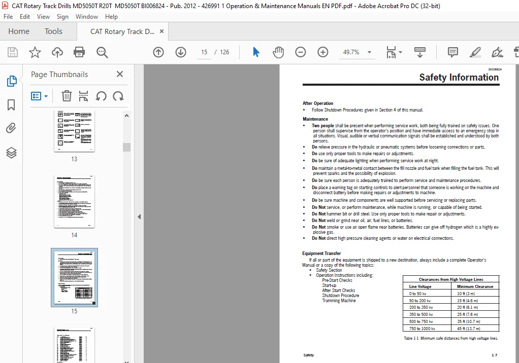
After Operation
• Follow Shutdown Procedures given in Section 4 of this manual
Maintenance
• Two people shall be present when performing service work, both being fully trained on safety issues. One person shall supervise from the operator’s position and have immediate access to an emergency stop in all situations.
Visual, audible or verbal communication signals shall be established and understood by both persons.
• Do relieve pressure in the hydraulic or pneumatic systems before loosening connections or parts.
• Do use only proper tools to make repairs or adjustments.
• Do be sure of adequate lighting when performing service work at night.
• Do maintain a metal-to-metal contact between the fill nozzle and fuel tank when filling the fuel tank. This will prevent sparks and the possibility of explosion.
• Do be sure each person is adequately trained to perform service and maintenance procedures.
• Do place a warning tag on starting controls to alert personnel that someone is working on the machine and disconnect battery before making repairs or adjustments to machine. • Do be sure machine and components are well supported before servicing or replacing parts.
• Do Not service, or perform maintenance, while machine is running, or capable of being started.
• Do Not hammer bit or drill steel. Use only proper tools to make repair or adjustments.
• Do Not weld or grind near oil, air, fuel lines, or batteries.
• Do Not smoke or use an open flame near batteries. Batteries can give off hydrogen which is a highly explosive gas.
• Do Not direct high pressure cleaning agents or water on electrical connections
TABLE OF CONTENTS:
Bucyrus MD5050T Hydraulic Track Drill Operation & Maintenance Manual- CAT Rotary Track Drill MD5050T – PDF DOWNLOAD
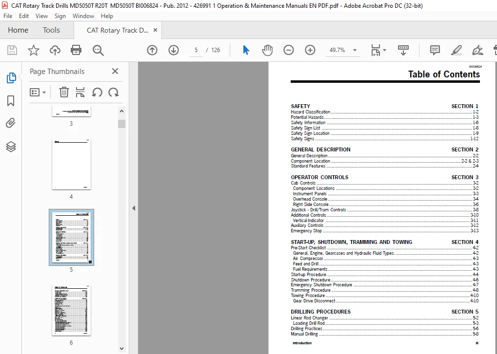
SAFETY SECTION 1
Hazard Classification 1-2
Potential Hazards 1-3
Safety Information 1-6
Safety Sign List 1-8
Safety Sign Location 1-9
Safety Signs 1-12
GENERAL DESCRIPTION SECTION 2
General Description 2-2
Component Location 2-2 & 2-3
Standard Features 2-4
OPERATOR CONTROLS SECTION 3
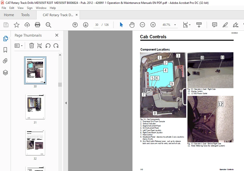
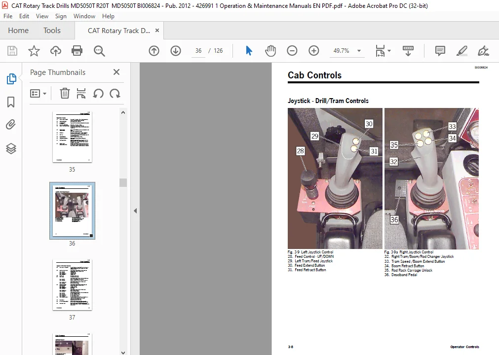
Cab Controls 3-2
Component Locations 3-2
Instrument Panels 3-3
Overhead Console 3-4
Right Side Console 3-6
Joystick – Drill/Tram Controls 3-8
Additional Controls 3-10
Vertical Indicator 3-11
Auxiliary Controls 3-12
Emergency Stop 3-13
START-UP, SHUTDOWN, TRAMMING AND TOWING SECTION 4
Pre-Start Checklist 4-2
General, Engine, Gearcases and Hydraulic Fluid Types 4-2
Air Compressor 4-3
Feed and Drill 4-3
Fuel Requirements 4-3
Start-up Procedure 4-4
Shutdown Procedure 4-6
Emergency Shutdown Procedure 4-7
Tramming Procedure 4-8
Towing Procedure 4-10
Gear Drive Disconnect 4-10
DRILLING PROCEDURES SECTION 5
Linear Rod Changer 5-2
Loading Drill Rod 5-3
Drilling Practices 5-6
Manual Drilling 5-8
BI006824
iv Introduction
Table of Contents
Collaring the Hole 5-9
Smart Drill Feature 5-12
Adding Drill Rod (linear rod changer) 5-15
Removing Drill Rod (linear rod changer) 5-21
HPR1H-ATW Drill Shank Replacement 5-24
HPR4519 Drill Shank Replacement 5-26
PREVENTIVE MAINTENANCE SECTION 6
Hydraulic Oils for Percussion Drills 6-2
Lubrication and Inspection 6-3
Bolt Maintenance 6-3
Bolt Torque Specifications 6-4
Maintenance Schedule 6-5
Daily Operational Checklist 6-6
Hydraulic Drill 6-7
Accumulator Charge Pressure – Check Monthly 6-7
Engine Oil Filter 6-8
Engine Fuel Filter 6-9
Fuel/Water Separator 6-9
Engine Air Cleaner Filter 6-10
Compressor Air Cleaner Filter 6-11
Compressor Oil Filter 6-12
Compressor Oil Check/Change 6-13
Compressor Oil Separator Element 6-14
Detergent System (Optional) 6-16
Servicing the “Y” Strainer 6-17
Detergent System Freeze Protection 6-17
Hydraulic Fluid Fill Pump and Filter 6-18
Hydraulic Return Filter 6-19
Coolant System 6-21
Track Tension Adjustment 6-23
R20T Grease Points – overall machine 6-24
Grease Points – HPR4519 Rock Drill 6-26
Grease Points – HPR1H-ATW Rock Drill (optional) 6-27
Grease Points – Centralizer & Cylinder Feed 6-28
Grease Points – UFH Chain Feed (optional) 6-29
Grease Points – Lower Rod Rack 6-30
Grease Points – Rod Wrench & Rod Rack Driveline 6-31
Grease Points – Upper Rod Rack 6-32
Grease Points – Feed Table 6-33
Grease Points – Boom Assembly 6-34
Grease Points – Swing Drive 6-35
Engine Fan Drive Bearing 6-36
Maintenance Record 6-37
BUCYRUS MD5050T HYDRAULIC TRACK DRILL OPERATION & MAINTENANCE MANUAL- CAT ROTARY TRACK DRILL MD5050T – PDF DOWNLOAD:
IMAGES PREVIEW OF THE MANUAL:


PLEASE NOTE:
- This is the same manual used by the dealers to diagnose and troubleshoot your vehicle
- You will be directed to the download page as soon as the purchase is completed. The whole payment and downloading process will take anywhere between 2-5 minutes
- Need any other service / repair / parts manual, please feel free to contact [email protected] . We still have 50,000 manuals unlisted
S.M