
Can-Am Outlander & Renegade 500 650 800 ATV Service Manual 2007-2008 PDF
Original price was: $41.95.$27.95Current price is: $27.95.
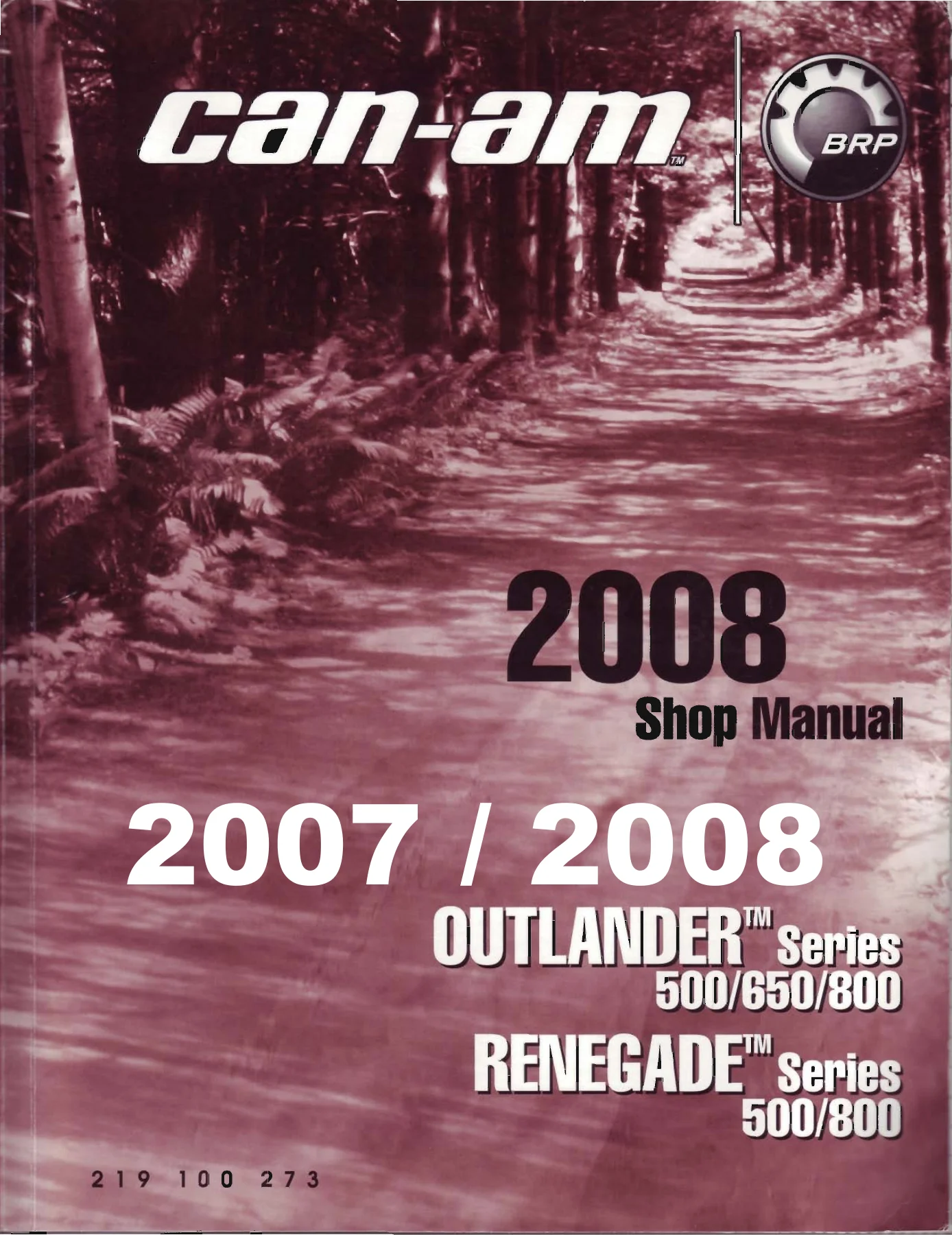
Complete 2008 Can-Am Shop Manual for the 2007 and 2008 Outlander 500/650/800 and Renegade 500/800 ATVs. 504 pages covering engine, gearbox, EMS, CVT, electrical, brakes, suspension, body and full wiring diagrams.
Description
2007-2008 Can-Am Outlander & Renegade 500 / 650 / 800 ATV Service Manual
This is the complete 2008 Can-Am Shop Manual published by BRP for the 2007 and 2008 Outlander Series 500/650/800 and Renegade Series 500/800 ATVs. At 504 pages it is the same working reference a Can-Am technician uses in the shop: every scheduled service, every rebuild procedure and every factory torque value the engineers specified for these machines. Whether you ride an Outlander 500 XT, a MAX 650, an 800 Ltd or a Renegade 800, the procedures in this Can-Am Outlander and Renegade service manual apply directly to your machine and to the job in front of you.
File Details
- Manual type: Shop Manual (Service Manual)
- Brand: Can-Am (Bombardier Recreational Products / BRP)
- Models covered: Outlander Series 500/650/800, Renegade Series 500/800
- Model years: 2007 / 2008
- Engines: V490, V660, V810
- Language: English
- Page count: 504
- File format: PDF
Chapters Covered
- 01 Maintenance
- 02 Special Procedures
- 03 Engine and Gearbox (V490/V660/V810)
- 04 Engine Management (V490/V660/V810)
- 05 Fuel System
- 06 Electrical System
- 07 Transmission
- 08 Drivetrain
- 09 Steering System
- 10 Suspension
- 11 Brakes
- 12 Body/Frame
- 13 Technical Specifications
- 14 Electrical Connectors and Wiring Diagrams
01 Maintenance
The maintenance chart runs from the initial 10-hour / 300 km service up through the 200-hour / 6000 km interval, and the chapter also covers the storage procedures — fuel stabilizer, engine lubrication, rags in the CVT inlet and outlet, coolant density, and drive and driven pulley protection — plus the seasonal preparation steps for a stored ATV.
02 Special Procedures
Turn-over diagnostics for a check engine light that stays on after startup, and the ATV immersion procedure split into two cases: a machine submerged for less than an hour and one submerged for longer. Both paths cover draining the engine oil, draining the CVT housing, flushing the fuel system and re-lubricating cables.
03 Engine and Gearbox (V490/V660/V810)
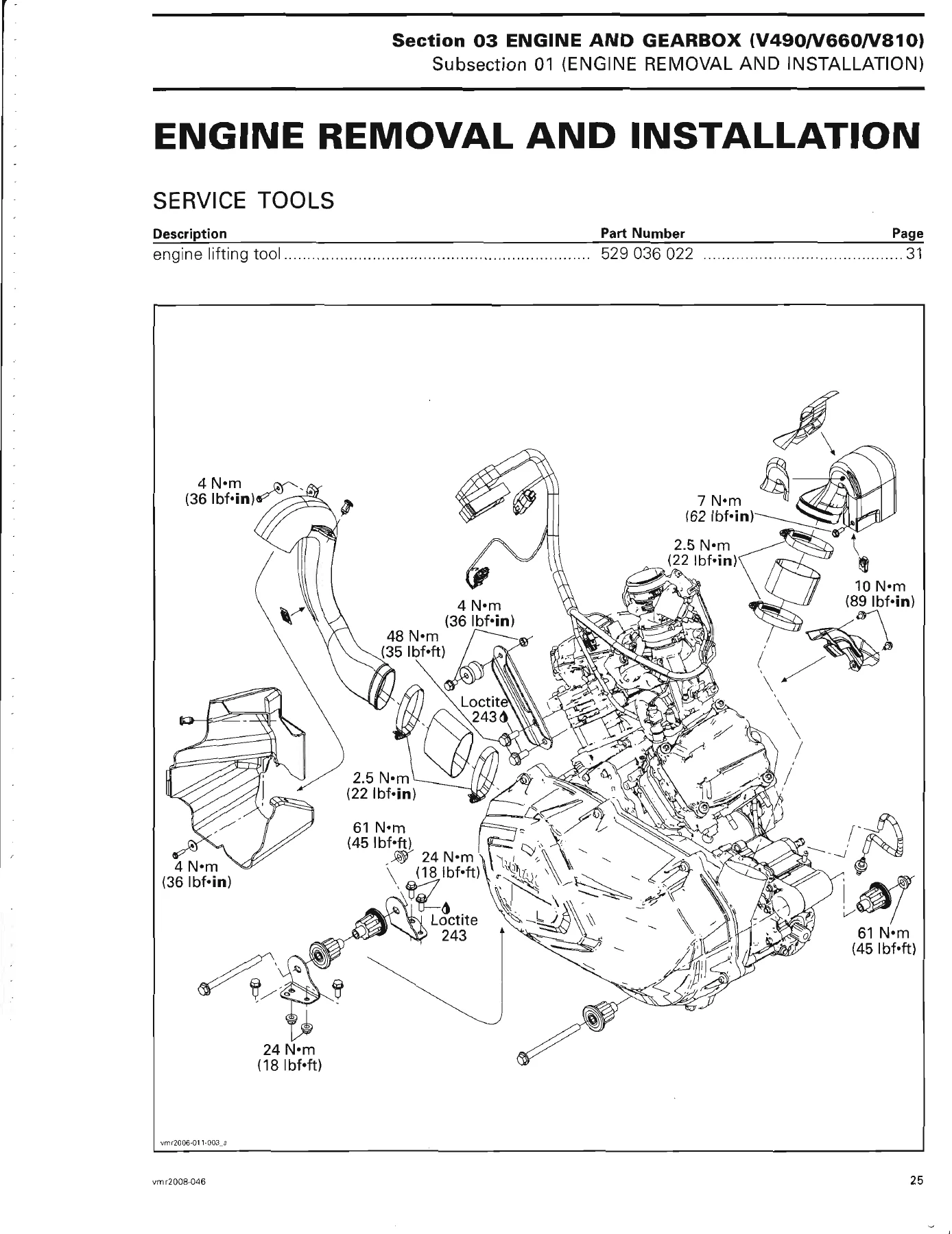
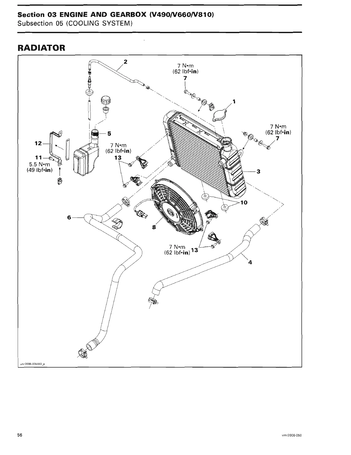
The largest chapter in the manual. It opens with engine removal and installation using the engine lifting tool (P/N 529 036 022), then walks through the air intake system, exhaust system, lubrication system (oil pump, regulator, filter, strainer, oil pressure test), cooling system (thermostat, radiator, fan, water pump housing, water pump shaft and seals), magneto system (stator, rotor, sprag clutch, starter drive gears), intake manifold and cylinder head and cylinder (valve adjustment, leak test, camshaft timing, rocker arms, valve springs, valves, valve guides, cylinder, piston, piston rings), bottom end (crankcase, crankshaft, connecting rods, plain bearings, timing chains), gearbox and 4×4 coupling unit, and shifter. Every exploded view carries torque values and service products printed right on the drawing.
04 Engine Management (V490/V660/V810)
Operating principle of the EMS, the fault code table, the EMS diagnostic flow chart, and adjustment and repair procedures for the main relay (R2), D1 diode, ECM, fuel injectors, fuel rail, throttle body, throttle position sensor (TPS), idle bypass valve (IBV), crankshaft position sensor (CPS), camshaft position sensor (CAPS), manifold air pressure and temperature sensor (MAPTS) and coolant temperature sensor (CTS).
05 Fuel System
Fuel tank and fuel pump module, fuel tank leak test, fuel pressure test, fuel hose and Oetiker clamps, in-line fuel filter, and a system diagnostic flow chart. The pressure regulator and fuel level sender live in this chapter too.
06 Electrical System
Communication tools and B.U.D.S. software (MPI and MPI-2 interfaces), ignition system, charging system (voltage regulator/rectifier, stator, battery, main ground), starting system (fuses, D2 diode, start button, starting solenoid, electric starter), Digitally Encoded Security System (DESS) key programming, and lights, gauge and accessories including the multifunction speedometer, vehicle speed sensor, fuel level sender, multifunction switch, 12-volt outlets, headlamp, taillight, winch, winch control switch and D5/D6 diodes.
07 Transmission
Continuously Variable Transmission (CVT) — drive belt, drive pulley, driven pulley and CVT air guide. The chapter includes the one-way clutch inspection and the slider shoe, governor cup and lever wear checks that decide how the CVT behaves under acceleration and deceleration.
08 Drivetrain
Front drive and rear drive. Tires and wheels, wheel hubs, front drive shaft, drive shaft boot, front differential, front propeller shaft, propeller shaft U-joint, rear differential protector and rear drive shaft.
09 Steering System
Handlebar grip and cover, handlebar, steering column and column bearing, tie-rod, knuckle, wheel bearing, multifunction switch, throttle handle, handle brake and steering alignment.
10 Suspension
Front suspension (shock absorber and spring, lower suspension arm protector, lower and upper suspension arms, lower and upper ball joints, upper suspension arm bracket) and rear suspension (rear shock, torsion bar, trailing arm, trailing arm bearings). Tires and wheels are covered in both halves.
11 Brakes
Brake fluid, rear and front brake light switches, parking brake mechanism, brake lever, front and rear master cylinders, brake pads, brake disc, brake pedal and brake hoses.
12 Body/Frame
Decals, seat, central panel, dashboard, side panels, footrests, inner fenders, heavy duty bumper, front bumper / front skid plate / front fascia, luggage rack, fenders and fender supports, plus the frame section covering footrest support, battery support, hitch, recovery hook and the frame itself.
13 Technical Specifications
Full spec tables for the Outlander Series and the Renegade models — the values a technician checks against before calling a part good or out of tolerance.
14 Electrical Connectors and Wiring Diagrams
Deutsch connectors, ECM connectors, multifunction speedometer connector, battery and starter cable terminals, wiring connectors coding, and the complete wiring diagrams for the 2007 and 2008 models.
What This Can-Am Outlander & Renegade Manual Lets You Do
Routine maintenance is the easy part: torque the suspension bolts to the values on the exploded views, set valve clearance with the feeler gauge ranges in the cylinder head chapter, adjust the drive belt, flush the coolant, replace the in-line fuel filter. The manual carries the interval charts and the storage and seasonal procedures so the machine is ready when the season starts.
The harder jobs are why this Can-Am workshop manual earns its place on the bench. Rebuilding the water pump and replacing both seals, re-timing the camshafts with the camshaft locking tool (P/N 529 035 926) and the crankshaft locking bolt (P/N 529 035 617), pulling the gearbox and setting up the bevel gear with the correct shim, replacing the one-way clutch on the drive pulley, rebuilding the brake master cylinder, tracking down an intermittent fault code through the ECM connector chart — each of those is a step-by-step procedure here, with the torque specs and service limits printed next to the parts they belong to.
Built for Real Shop Work
The manual does not stop at the big-ticket jobs. Torque values are printed on every exploded view, so you do not have to flip to a separate chart when you are tightening the crankcase or re-securing the cylinder head. Service limits for camshaft lobes, cylinder taper, out of round, valve stem and guide clearance, connecting rod big end radial play and piston ring end gaps are collected in the relevant chapters, not buried in an appendix. The electrical chapter includes the B.U.D.S. interface details and connector pinouts, so the diagnostics side of the manual is as usable as the mechanical side. A full wiring diagram section closes out the manual for the 2007 and 2008 model years.
Why Buy the PDF Version
PDF delivery means no shipping, no waiting and no damaged binder on arrival — the file lands in your inbox right after payment, opens on a phone, laptop or tablet in the workshop, and prints cleanly on any home or shop printer when you want paper next to the machine. Page numbers in the manual line up with the printed table of contents, so you can jump straight to the engine removal exploded view or the fuel pressure test without scanning through a scan of a scan.
If you own a 2007 or 2008 Outlander or Renegade, this Can-Am ATV service manual PDF covers the whole machine in one file. Buy it once and it stays with the machine for the rest of its life.
IMAGES PREVIEW
Reviews
There are no reviews yet.