Canadair Regional Jet Chapter 71 Power Plant Aircraft Maintenance Manual – CF34−3A1 CF34−3B1
$49.95 Original price was: $49.95.$29.95Current price is: $29.95.
710-page Canadair Regional Jet Aircraft Maintenance Manual covering Chapter 71 Power Plant maintenance for installations using General Electric CF34−3A1 and CF34−3B1 engines. Includes power plant removal and installation, engine ground-run procedures, cowling, engine mounts, electrical harnesses, nose inlet cowl, drain and vent systems, inspections, checks, servicing and temporary revision material.
Description
Canadair Regional Jet Chapter 71 Power Plant Aircraft Maintenance Manual – CF34−3A1 CF34−3B1
This Canadair Regional Jet Chapter 71 Power Plant Aircraft Maintenance Manual – CF34−3A1 CF34−3B1 is a detailed maintenance reference devoted to ATA Chapter 71 power plant installation, supporting systems and related airframe-mounted components. The chapter covers the complete power plant assembly, nacelle and cowling structures, forward and aft engine mounting hardware, engine-related electrical harnesses, nose inlet-cowl installation and the drain and vent system. It also contains extensive procedures for power plant servicing, removal and installation, engine ground operation, inspections and operational checks.
The manual identifies installations using General Electric CF34−3A1 and CF34−3B1 high-bypass turbofan engines. A particularly important part of the chapter is its effectivity guidance surrounding Service Bulletin 601R−71−027. The manual instructs maintenance personnel to determine the actual engine configuration from the aircraft Service Bulletin records before selecting the applicable CF34−3A1 or CF34−3B1 procedure, because post-modification aircraft may have an engine combination that differs from a procedure’s normal effectivity indication.
File Details
- Manual type: Aircraft Maintenance Manual – Chapter 71 Power Plant
- Aircraft: Canadair Regional Jet
- Engines covered: General Electric CF34−3A1 and CF34−3B1
- Language: English
- Page count: 710 pages
- File format: PDF
- Master revision date: Dec 10/2005
- Temporary revision included: TR# 71−130, Feb 27/2006
Power Plant Maintenance Scope
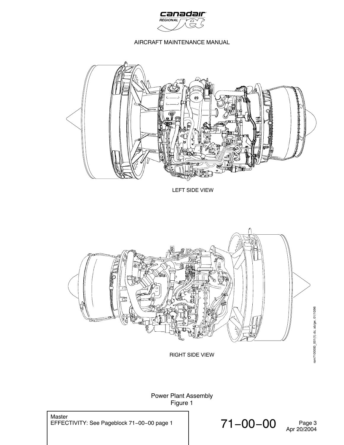
The opening power plant section describes the twin power plant arrangement and the principal nacelle, mounting and accessory relationships. It explains how the nacelle incorporates the nose inlet cowl, translating cowls, core cowls, access panels, exhaust nozzle fairing and thrust reverser. The forward mounting arrangement uses a yoke connected to the aircraft structure, while the rear installation uses a thrust fitting and thrust mount to transmit engine thrust to the airframe.
The general Chapter 71 maintenance material goes well beyond component identification. It provides procedures for installing and removing the boot strap assembly, supporting the power plant with a sling, preservation and depreservation, complete power plant removal and installation, and the preparation needed before engine operation. Removal and installation work includes detailed job setup, tooling, access requirements, disconnection and reconnection steps, mount inspections and post-installation checks.
Engine Ground Operation and Functional Checks
A substantial portion of this Canadair Regional Jet power plant maintenance manual is dedicated to controlled engine operation after maintenance. Procedures cover engine operating limits, emergency and abnormal operating conditions, preparation for ground runs, prestart checks, engine starting, post-start checks, normal shutdown and post-run checks. Separate procedures are provided for dry and wet motor cycles, idle-speed adjustment and engine break-in running.
The inspection and test material supports troubleshooting and verification after maintenance. Included procedures cover acceleration and deceleration, N1 speed-control amplifier disable checks, bleed-air supply checks, thrust-reverser operational checks, Automatic Power Reserve operational checks, power assurance checks, oil-consumption checks and vibration monitoring. The chapter also includes fuel and oil leak checks, bleed-air leak checks, fan tie-down leak checks, field trim balancing for noise reduction and a core vibration check.
Complete Bookmarks
The complete bookmarks in the “Canadair Regional Jet Chapter 71 Power Plant Aircraft Maintenance Manual – CF34−3A1 CF34−3B1” are as follows:
+Chapter 71p. 710
+Section 00p. 23
+71-00-00p. 23
+1: POWER PLANT – DESCRIPTION AND OPERATIONp. 23
+Power Plant Assemblyp. 25
+201: POWER PLANT – MAINTENANCE PRACTICESp. 27
+Task 71-00-00-490-801 Installation of the Boot Strap Assemblyp. 27
+Boot Strap Assembly – Removal/Installationp. 34
+Boot Strap – Removal/Installationp. 35
+Boot Strap – Removal/Installationp. 36
+Boot Strap Assembly – Removal/Installationp. 37
+Boot Strap Removal/Installationp. 38
+Boot Strap – Removal/Installationp. 39
+Task 71-00-00-090-801 Removal of the Boot Strap Assemblyp. 40
+Task 71-00-00-581-801 Hold the Power Plant with the Sling for Maintenancep. 46
+Power Plant Lifting Sling – Removal/Installationp. 51
+301: POWER PLANT – SERVICINGp. 53
+Task 71-00-00-620-801 Preservation of Installed Enginesp. 53
+Power Plant – Servicingp. 59
+Task 71-00-00-630-801 Depreservation of Installed Enginesp. 60
+Power Plant Servicing – Depreservation of the Fuel Linesp. 64
+Task 71-00-00-630-802 Depreservation of New or Overhauled Engine Fuel-System Componentsp. 65
+401: POWER PLANT – REMOVAL/INSTALLATIONp. 69
+Task 71-00-00-000-801 Removal of the Power Plantp. 69
+Power Plant – Removal/Installationp. 85
+Power Plant – Removal/Installationp. 89
+Power Plant – Removal/Installationp. 90
+Power Plant (CF34-3A1 Engine) – Removal/Installationp. 91
+Power Plant (CF34-3B1 Engine) – Removal/Installationp. 92
+Engine Mounts – Removal/Installationp. 93
+Task 71-00-00-400-801 Installation of the Power Plantp. 95
+501: POWER PLANT – ADJUSTMENT/TESTp. 119
+Task 71-00-00-868-804 Engine Operating Limitsp. 119
+Core Rotor (N2) Overspeed Limitsp. 142
+Fan Rotor (N1) Overspeed Limitsp. 143
+Flight Envelope-Ambient Temperature Extremesp. 144
+Oil PRESSURE VS N2% Speedp. 145
+For CF34-3A1 – Overtemperature Limits (ITT VS Time)p. 146
+For CF34-3B1 – Overtemperature Limits (ITT VS Time)p. 147
+Corrected Core Speed Limitp. 148
+Nominal Idle Speed as Function of T2 and Altitudep. 149
+Task 71-00-00-868-816 Engine Emergency Proceduresp. 150
+Task 71-00-00-868-815 Abnormal Engine Operationp. 159
+Task 71-00-00-868-801 Preparation for Ground Runp. 166
+Aircraft Danger Areasp. 171
+Aircraft Wind Directionp. 172
+External Walk Aroundp. 173
+Task 71-00-00-868-805 Prestart Checksp. 174
+Flight Compartment Prestart Flow Schematicp. 185
+Flight Component Location/Recognitionp. 186
+Task 71-00-00-868-806 Engine Startp. 187
+14 Stage Bleed Air Indication/Descriptionp. 211
+10TH STAGE BLEED AIRp. 212
+Engine Fuel System Action Results and indicationp. 213
+Maximum Allowable Ground Start Time Compared to Fan Inlet Temperaturep. 214
+Task 71-00-00-710-812 After Engine Start Checksp. 215
+Task 71-00-00-868-807 Engine Shutdown (Normal)p. 217
+Task 71-00-00-868-809 Engine Post Run Checksp. 219
+Task 71-00-00-868-811 Engine Dry Motor Cyclep. 223
+Task 71-00-00-868-812 Engine Wet Motor Cyclep. 230
+Task 71-00-00-868-813 Idle Speed Adjustmentp. 238
+Idle Speed Limitsp. 252
+Idle Speed Adjustmentp. 253
+Task 71-00-00-868-814 Engine Break-In Runp. 254
+601: POWER PLANT – INSPECTION/CHECKp. 259
+Task 71-00-00-710-802 Acceleration and Deceleration Checkp. 259
+Acceleration Time Limitsp. 271
+Task 71-00-00-710-803 N1 Speed-Control Amplifier-Disable-Checkp. 272
+Task 71-00-00-710-805 Bleed-Air Supply Checkp. 277
+Pneumatic Flow Chartp. 283
+Task 71-00-00-710-806 Thrust-Reverser Operational Checkp. 284
+Task 71-00-00-710-807 Automatic Power Reserve (APR) Operational Checkp. 289
+Task 71-00-00-710-808 Power Assurance Checkp. 291
+Task 71-00-00-710-810 Oil Consumption Checkp. 323
+Task 71-00-00-710-811 Vibration Checkp. 325
+Task 71-00-00-790-801 Fuel and Oil Leak Checkp. 329
+Task 71-00-00-790-802 Bleed Air Leak-Checkp. 335
+Task 71-00-00-790-803 Fan Tie-Down Leak Checkp. 338
+Fan Tiedown Strap Installationp. 346
+Task 71-00-00-720-801 Field Trim-Balance for Noise-Reductionp. 347
+Task 71-00-00-720-802 Core Vibration Checkp. 354
+Section 10p. 355
+71-10-00p. 355
+1: COWLING – DESCRIPTION AND OPERATIONp. 355
+2. Component Detailsp. 355
+Cowling Componentsp. 358
+Nose Cowl Assemblyp. 359
+Upper and Lower Nose Access-Cowlsp. 360
+Forward Core-Cowl Assemblyp. 361
+Translating Cowl Assemblyp. 362
+Core Cowl Assemblyp. 363
+Fixed Core-Cowl Side Panel and Service Pylonp. 364
+Fixed Nose Cowlp. 365
+Section 11p. 367
+71-11-01p. 367
+201: DOORS, TRANSLATING COWL – MAINTENANCE PRACTICESp. 367
+Task 71-11-01-010-801 Open the Upper Translating-Cowl Doorp. 367
+Open and Close the Translating Cowl Doorsp. 369
+Task 71-11-01-410-801 Close the Upper Translating-Cowl Doorp. 371
+Task 71-11-01-010-802 Open the Lower Translating-Cowl Doorp. 372
+Task 71-11-01-410-802 Close the Lower Translating-Cowl Doorp. 374
+401: DOORS, TRANSLATING COWL – REMOVAL/INSTALLATIONp. 375
+Task 71-11-01-000-801 Removal of the Upper Translating-Cowl Doorp. 375
+Upper and Lower Translating-Cowl Doors – Removal/Installationp. 377
+Task 71-11-01-400-801 Installation of the Upper Translating-Cowl Doorp. 378
+Task 71-11-01-000-802 Removal of the Lower Translating-Cowl Doorp. 380
+Task 71-11-01-400-802 Installation of the Lower Translating-Cowl Doorp. 382
+501: DOORS, TRANSLATING COWL – ADJUSTMENT/TESTp. 385
+Task 71-11-01-820-801 Adjustment of the Translating Cowl Doorsp. 385
+Translating Cowl Doors – Adjustment/Testp. 387
+601: DOORS, TRANSLATING COWL – INSPECTION/CHECKp. 389
+Task 71-11-01-210-801 Inspection of the Translating Cowl Doorsp. 389
+Section 12p. 393
+71-12-01p. 393
+201: CORE COWL DOORS – MAINTENANCE PRACTICESp. 393
+Task 71-12-01-010-801 Open the Upper Core-Cowl Doorp. 393
+Open and Close the Core Cowl Doors – Pre SB CF34-NAC-71-013p. 395
+Open and Close the Core Cowl Doors – Post SB CF34-NAC-71-013p. 397
+Task 71-12-01-410-802 Close the Upper Core-Cowl Doorp. 399
+Task 71-12-01-010-803 Open the Lower Core-Cowl Doorp. 401
+Task 71-12-01-410-804 Close the Lower Core-Cowl Doorp. 403
+401: CORE COWL DOORS – REMOVAL/INSTALLATIONp. 405
+Task 71-12-01-000-801 Removal of the Upper Core-Cowl Doorp. 405
+Core Cowl Assembly (Pre SB CF34-NAC-71-013) – Removal/Installationp. 407
+Core Cowl Assembly (Post SB CF34-NAC-71-013) – Removal/Installationp. 408
+Task 71-12-01-400-801 Installation of the Upper Core-Cowl Doorp. 409
+Task 71-12-01-000-802 Removal of the Lower Core-Cowl Doorp. 411
+Task 71-12-01-400-802 Installation of the Lower Core-Cowl Doorp. 413
+501: CORE COWL DOORS – ADJUSTMENT/TESTp. 415
+Task 71-12-01-820-801 Adjustment of the Core-Cowl Door Latchesp. 415
+Core-Cowl Door Latch – Adjustment/Testp. 417
+601: CORE COWL DOORS – INSPECTION/CHECKp. 419
+Task 71-12-01-210-801 Inspection and Check of the Core Cowl Doorsp. 419
+Task 71-12-01-220-801 Detailed Inspection of the Core-Cowl Blowout Doorp. 422
+Section 13p. 423
+71-13-01p. 423
+401: SIDE-PANEL, FIXED CORE-COWL – REMOVAL/INSTALLATIONp. 423
+Task 71-13-01-000-801 Removal of the Fixed Core-Cowl Side-Panelp. 423
+Core-Cowl Side Panel – Removal/Installationp. 425
+Task 71-13-01-400-801 Installation of the Fixed Core-Cowl Side-Panelp. 429
+Section 14p. 433
+71-14-01p. 433
+401: NOSE ACCESS COWLS – REMOVAL/INSTALLATIONp. 433
+Task 71-14-01-000-801 Removal of the Upper Nose Access-Cowlp. 433
+Upper and Lower Nose Access-Cowl – Removal/Installationp. 434
+Task 71-14-01-400-801 Installation of the Upper Nose Access-Cowlp. 435
+Task 71-14-01-000-802 Removal of the Lower Nose Access-Cowlp. 437
+Task 71-14-01-400-802 Installation of the Lower Nose Access-Cowlp. 438
+601: NOSE ACCESS COWLS – INSPECTION/CHECKp. 441
+Task 71-14-01-210-802 Inspection of the Nose Access Cowlsp. 441
+Nose Access Cowls – Inspection/Checkp. 445
+71-14-07p. 447
+401: STOP ASSEMBLY, ACCESS-COWL ALIGNMENT – REMOVAL/INSTALLATIONp. 447
+Task 71-14-07-000-801 Removal of the Access-Cowl Alignment-Stop Assemblyp. 447
+Access-Cowl Alignment-Stop Assembly – Removal/Installationp. 449
+Access-Cowl Alignment-Stop Assembly – Removal/Installationp. 450
+Task 71-14-07-400-801 Installation of the Access-Cowl Alignment-Stop Assemblyp. 451
+Section 16p. 455
+71-16-00p. 455
+401: FORWARD CORE COWL – REMOVAL/INSTALLATIONp. 455
+Task 71-16-00-000-801 Removal of the Forward Core Cowlp. 455
+Forward Core Cowl – Removal/Installationp. 457
+Task 71-16-00-400-801 Installation of the Forward Core Cowlp. 459
+601: FORWARD CORE COWL – INSPECTION/CHECKp. 463
+Task 71-16-00-210-801 Inspection of the Forward Core Cowlp. 463
+Detailed Inspection of the Engine Forward Core Cowlp. 465
+Section 20p. 467
+71-20-00p. 467
+1: ENGINE MOUNTS – DESCRIPTION AND OPERATIONp. 467
+Engine Mounting Pointsp. 468
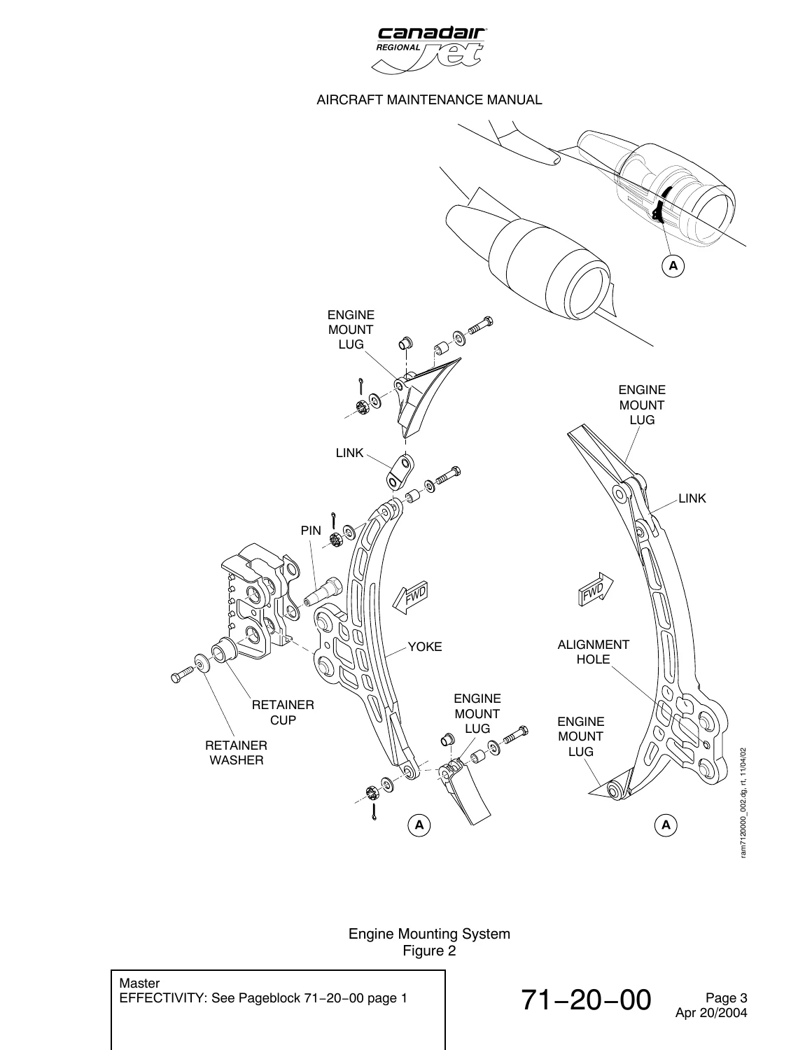
+Engine Mounting Systemp. 469
+Rear Engine Mountp. 470
+Section 21p. 471
+71-21-01p. 471
+401: ENGINE MOUNT, FORWARD – REMOVAL/INSTALLATIONp. 471
+Task 71-21-01-000-801 Removal of the Forward Engine Mountp. 471
+Forward Engine Mount – Removal/Installationp. 473
+Task 71-21-01-400-801 Installation of the Forward Engine Mountp. 475
+601: ENGINE MOUNT, FORWARD – INSPECTION/CHECKp. 479
+Task 71-21-01-210-801 Detailed Inspection of the Forward Engine Mount Assemblyp. 479
+Task 71-21-01-220-801 Detailed Inspection of the Forward Engine Mount Boltp. 483
+Forward Engine Mount Bolt – Inspection/Checkp. 486
+Task 71-21-01-210-802 Detailed Inspection of the Forward Engine-Mount Yoke Assemblyp. 487
+Forward Engine-Mount Yoke Assembly – Inspection/Checkp. 491
+Task 71-21-01-210-803 General Visual Inspection of the Pylon Sparp. 496
+701: ENGINE MOUNT, FORWARD – CLEANINGp. 499
+Task 71-21-01-100-801 Cleaning of the Forward Engine Mount Boltp. 499
+801: ENGINE MOUNT, FORWARD – REPAIRp. 503
+Task 71-21-01-350-801 Application of Solid Film Lubricant to the Forward Engine Mount Boltp. 503
+Task 71-21-01-350-802 Replacement of the Heli-Coil Thread Insert in the Forward Engine Mount Boltp. 505
+Application of Solid Film Lubricantp. 507
+Thread Insert Replacementp. 508
+71-21-03p. 509
+601: LINK ASSEMBLY, FORWARD ENGINE MOUNTp. 509
+Task 71-21-03-220-801 Detailed Inspection of the Forward Engine-Mount Link Assemblyp. 509
+Link Assembly-Forward Engine Mount.p. 513
+Section 22p. 515
+71-22-01p. 515
+401: THRUST-FITTING, AFT ENGINE-MOUNT – REMOVAL/INSTALLATIONp. 515
+Task 71-22-01-000-801 Removal of the Aft Engine-Mount Thrust-Fittingp. 515
+Aft Engine Mount Thrust Fitting – Removal/Installationp. 517
+Task 71-22-01-400-801 Installation of the Aft Engine-Mount Thrust-Fittingp. 518
+Installation Check of the Thrust Fittingp. 522
+Task 71-22-01-000-802 Removal of the Aft Engine-Mount Thrust-Fitting Plug-Assemblyp. 523
+Task 71-22-01-400-802 Installation of the Aft Engine-Mount Thrust-Fitting Plug-Assemblyp. 524
+601: THRUST-FITTING, AFT ENGINE-MOUNT – INSPECTION/CHECKp. 525
+Task 71-22-01-210-801 Detailed Inspection of the Rear Engine Mount and Componentsp. 525
+Inspection of the Aft Engine-Mount Thrust Fittingp. 529
+Task 71-22-01-210-802 Detailed Inspection of the Engine Thrust-Mount Assemblyp. 530
+Engine Thrust Mount Assembly – Inspectionp. 532
+Task 71-22-01-210-803 Inspection of the Thrust-Mount Assembly Componentsp. 533
+Inspection of the Thrust Mount Assemblyp. 536
+Task 71-22-01-220-801 Detailed Inspection of the Aft Engine-Mount Thrust-Fittingp. 537
+Aft Engine-Mount Thrust-Fitting – Inspection/Checkp. 541
+71-22-03p. 547
+401: BUSHINGS AND BEARINGS, AFT ENGINE MOUNT – REMOVAL/INSTALLATIONp. 547
+Task 71-22-03-000-801 Removal of the Spherical Bushing and Housingp. 547
+Aft Engine Mount Bushings and Bearings – Removal/Installationp. 548
+Task 71-22-03-400-801 Installation of the Spherical Bushing and Housingp. 549
+Task 71-22-03-000-802 Removal of the Spherical Bearingp. 551
+Task 71-22-03-400-802 Installation of the Spherical Bearingp. 552
+71-22-05p. 555
+401: THRUST SHAFT, AFT ENGINE MOUNT – REMOVAL/INSTALLATIONp. 555
+Task 71-22-05-000-801 Removal of the Aft Engine-Mount Thrust Shaftp. 555
+Aft Engine-Mount Thrust Shaftp. 556
+Task 71-22-05-400-801 Installation of the Aft Engine-Mount Thrust Shaftp. 557
+601: THRUST SHAFT, AFT ENGINE MOUNT – INSPECTION/CHECKp. 559
+Task 71-22-05-220-801 Detailed Inspection of the Aft Engine-Mount Thrust Shaftp. 559
+Aft Engine-Mount Thrust Shaft – Inspection/Checkp. 561
+Section 30p. 565
+71-30-00p. 565
+1: NACELLE AND PYLON FIRESEALS – DESCRIPTION AND OPERATIONp. 565
+Nacelle and Pylon Fireseals – Generalp. 566
+601: NACELLE AND PYLON FIRESEALS – INSPECTION/CHECKp. 567
+Task 71-30-00-210-801 Inspection of the Power Plant Nacelle and Pylon Firesealsp. 567
+Section 50p. 571
+71-50-00p. 571
+1: ELECTRICAL HARNESS – DESCRIPTION AND OPERATIONp. 571
+401: ELECTRICAL HARNESS – REMOVAL/INSTALLATIONp. 573
+Task 71-50-00-000-801 Removal of the Violet Core-Cowl Harness – Left Enginep. 573
+Violet Core-Cowl Harness, Left Engine – Removal/Installationp. 576
+Task 71-50-00-400-801 Installation of the Violet Core-Cowl Harness – Left Enginep. 579
+Task 71-50-00-000-802 Removal of the Violet Core-Cowl Harness – Right Enginep. 582
+Violet Core-Cowl Harness, Right Engine – Removal/Installationp. 585
+Task 71-50-00-400-802 Installation of the Core-Cowl Master Harness B (Violet) – Right Enginep. 588
+Task 71-50-00-000-803 Removal of the Red Core-Cowl Harness – Left Enginep. 593
+Red Core-Cowl Harness, Left Engine – Removal/Installationp. 596
+Task 71-50-00-400-803 Installation of the Red Core-Cowl Harness – Left Enginep. 599
+Task 71-50-00-000-804 Removal of the Red Core-Cowl Harness – Right Enginep. 603
+Red Core-Cowl Harness, Right Engine – Removal/Installationp. 606
+Task 71-50-00-400-804 Installation of the Red Core-Cowl Harness – Right Enginep. 609
+Task 71-50-00-000-805 Removal of the Orange Electrical Harness – Left Enginep. 613
+Orange Electrical Harness, Left Engine – Removal/Installationp. 616
+Orange Electrical Harness, Left Engine – Removal/Installationp. 618
+Task 71-50-00-400-805 Installation of the Orange Electrical Harness – Left Enginep. 621
+Task 71-50-00-000-808 Removal of the Orange Electrical Harness – Right Enginep. 624
+Orange Electrical Harness, Right Engine – Removal/Installationp. 627
+Orange Electrical Harness, Right Engine – Removal/Installationp. 628
+Task 71-50-00-400-808 Installation of the Orange Electrical Harness – Right Enginep. 631
+601: ELECTRICAL HARNESS – INSPECTION/CHECKp. 635
+Task 71-50-00-220-801 Detailed Visual Inspection of the Red Core-Cowl Electrical Harnessp. 635
+Task 71-50-00-220-802 Detailed Visual Inspection of the Violet Core-Cowl Electrical Harnessp. 636
+Task 71-50-00-220-803 Detailed Visual Inspection of the Orange Nose-Cowl Electrical Harnessp. 637
+701: ELECTRICAL HARNESS – CLEANINGp. 639
+Task 71-50-00-100-801 Cleaning of the Electrical Connectorsp. 639
+Section 61p. 643
+71-61-00p. 643
+1: NOSE COWL ASSEMBLY – DESCRIPTION AND OPERATIONp. 643
+Nacelle Airflowp. 644
+71-61-01p. 645
+401: NOSE INLET-COWL ASSEMBLY – REMOVAL/INSTALLATIONp. 645
+Task 71-61-01-000-801 Removal of the Nose Inlet-Cowl Assemblyp. 645
+Nose Inlet-Cowl Assembly – Removal/Installationp. 653
+Nose Inlet-Cowl Assembly – Removal/Installationp. 654
+Nose Inlet-Cowl Assembly – Removal/Installationp. 656
+Nose Inlet-Cowl Assembly – Removal/Installationp. 658
+Nose Inlet-Cowl Assembly – Removal/Installationp. 659
+Nose Inlet-Cowl Assembly – Removal/Installationp. 660
+Nose Inlet-Cowl Assembly – Removal/Installationp. 661
+Task 71-61-01-400-801 Installation of the Nose Inlet-Cowl Assemblyp. 662
+601: NOSE INLET-COWL ASSEMBLY – INSPECTION/CHECKp. 673
+Task 71-61-01-210-801 Detailed Inspection of the Thrust Reverser Attach Fittingsp. 673
+Task 71-61-01-210-807 Visual Inspection of the Nose Inlet-Cowl Assemblyp. 676
+Nose Inlet-Cowl Assembly – Inspection/Checkp. 679
+Section 70p. 681
+71-70-00p. 681
+1: DRAIN AND VENT SYSTEM – DESCRIPTION AND OPERATIONp. 681
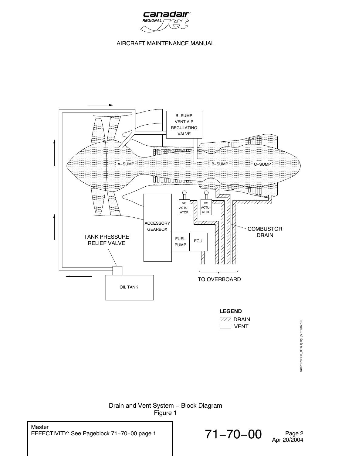
+Drain and Vent System – Block Diagramp. 682
+Section 71p. 683
+71-71-01p. 683
+401: OVERBOARD DRAIN ASSEMBLY – REMOVAL/INSTALLATIONp. 683
+Task 71-71-01-000-801 Removal of the Overboard Drain Assemblyp. 683
+Overboard Drain Assembly – Removal/Installationp. 685
+Task 71-71-01-400-801 Installation of the Overboard Drain Assemblyp. 686
+Task 71-71-01-000-802 Removal of the Drain Manifoldp. 688
+Drain Manifold – Removal/Installationp. 690
+Task 71-71-01-400-802 Installation of the Drain Manifoldp. 691
+601: ENGINE DRAINS – INSPECTION/CHECKp. 695
+Task 71-71-01-210-801 General Visual Inspection of the Engine Drain Mastp. 695
+Engine Drain Mast – Inspection/Checkp. 696
+Task 71-71-01-210-802 General Visual Inspection of the Engine Combustor Overboard Drainp. 697
+Engine Combustor Overboard Drain – Inspection/Checkp. 699
The procedures contain the precautions, job setup, reference tasks and configuration-dependent instructions needed to conduct these operations methodically. For example, the chapter warns against operating above specified engine conditions with particular cowl doors or nose access cowls open or removed, and it incorporates post-run inspections when leaks or abnormal indications are found.
Chapters Covered
- 71−00−00 Power Plant
- Description and operation
- Boot strap assembly installation and removal
- Holding the power plant with the sling for maintenance
- Preservation and depreservation of installed engines
- Depreservation of new or overhauled engine fuel-system components
- Power plant removal and installation
- Engine operating limits
- Engine emergency procedures and abnormal engine operation
- Preparation for ground run and prestart checks
- Engine start, shutdown and post-run checks
- Engine dry motor and wet motor cycles
- Idle speed adjustment and engine break-in run
- Acceleration and deceleration check
- N1 speed-control amplifier-disable check
- Bleed-air supply check
- Thrust-reverser operational check
- Automatic Power Reserve operational check
- Power assurance and oil consumption checks
- Vibration, fuel/oil leak and bleed-air leak checks
- Fan tie-down leak check, field trim-balance and core vibration check
- 71−10−00 Cowling
- Nose inlet cowl and access cowls
- Forward and fixed core-cowl assemblies
- Translating cowl doors and core-cowl doors
- Service pylon and nose-cowl side panel
- 71−11−01 Translating Cowl Doors
- Opening and closing upper and lower doors
- Upper and lower door removal and installation
- Door adjustment and inspection
- 71−12−01 Core Cowl Doors
- Opening and closing upper and lower core-cowl doors
- Removal and installation
- Latch adjustment
- Inspection of core-cowl doors and blowout door
- 71−13−01 Fixed Core-Cowl Side Panel
- Removal and installation
- 71−14−01 / 71−14−07 Nose Access Cowls and Alignment Stop Assembly
- Upper and lower nose access-cowl removal and installation
- Nose access-cowl inspection
- Access-cowl alignment-stop assembly removal and installation
- 71−16−00 Forward Core Cowl
- Removal and installation
- Forward core-cowl inspection
- 71−20−00 Engine Mounts
- Engine mount description and operation
- Forward engine mount removal and installation
- Forward engine mount, bolt and yoke inspections
- Pylon spar inspection
- Forward engine mount bolt cleaning and repair procedures
- Forward engine mount link inspection
- Aft engine-mount thrust-fitting removal, installation and inspection
- Aft mount spherical bushing, housing and bearing removal and installation
- Aft engine-mount thrust shaft removal, installation and inspection
- 71−30−00 Nacelle and Pylon Fireseals
- Description
- Inspection of power plant nacelle and pylon fireseals
- 71−50−00 Electrical Harness
- Harness description and component details
- Red and violet core-cowl harness removal and installation for left and right engines
- Orange electrical harness removal and installation for left and right engines
- Detailed visual inspections of red, violet and orange harnesses
- Electrical connector cleaning
- 71−61−00 / 71−61−01 Nose Inlet-Cowl Assembly
- Description and operation
- Nose inlet-cowl assembly removal and installation
- Thrust-reverser attach fitting inspection
- Nose inlet-cowl visual inspection
- 71−70−00 / 71−71−01 Drain and Vent System
- Drain and vent system description
- Overboard drain assembly removal and installation
- Drain manifold removal and installation
- Engine drain mast inspection
- Engine combustor overboard drain inspection
Taken together, these sections provide a working maintenance reference from access and preparation through component removal, installation, inspection, adjustment and return-to-service checks. The manual’s extensive effectivity statements are particularly useful when identifying which configuration-specific procedure applies to a particular aircraft or engine installation.
Cowling, Nacelle and Access Components
The cowling section explains the construction and purpose of the nacelle and then follows the individual assemblies into hands-on maintenance procedures. The nose inlet cowl directs smooth airflow to the engine fan and contains anti-ice ducting and installation provisions associated with thrust-reverser operation. Access cowls, fixed and forward core-cowl assemblies, translating cowl doors and core-cowl doors are illustrated and described before their applicable removal, installation, adjustment and inspection tasks.
This is useful when maintenance requires opening the nacelle for access as well as when the cowling itself requires adjustment or component replacement. Procedures distinguish upper and lower translating and core-cowl doors and include inspection of hardware such as latches, blowout-door areas and alignment components.
IMAGES PREVIEW
Engine Mounts and Structural Interfaces
The engine-mount coverage is one of the strongest technical sections in the manual. Illustrations identify the forward mount yoke, links, pins, retainers and mounting lugs, while the aft mount material identifies the engine thrust mount, thrust fitting, thrust shaft, spherical bearing and associated bushings. The manual provides forward engine mount removal and installation followed by detailed inspection tasks for the mount assembly, bolts and yoke.
Aft mounting coverage includes thrust-fitting and plug-assembly work, spherical bushing and bearing replacement, thrust shaft maintenance and detailed inspections. Procedures include defined torque values, clearances, inspection requirements, consumables and close-out operations where applicable. Temporary Revision 71−130, dated Feb 27/2006, revises the aft engine-mount thrust-fitting removal/installation pageblock and the installation procedure for the aft engine-mount thrust fitting.
Electrical Harness, Inlet Cowl and Drain System Work
Chapter 71 also contains substantial electrical installation information rather than simply referring the reader elsewhere. It covers the red and violet core-cowl master harnesses and the orange nose-cowl accessories harness, with separate left- and right-engine removal and installation procedures. Connector locations, clips and related engine components are identified in detailed illustrations, and the chapter includes visual inspection procedures and electrical connector cleaning.
The nose inlet-cowl section gives the removal and installation sequence for the complete inlet-cowl assembly, including lifting and handling precautions, attachment details and configuration-dependent alignment-stop provisions. Inspections cover the assembly itself and thrust-reverser attachment fittings. The drain and vent section then describes how fluids and gases are routed away from the nacelle and includes a system block diagram plus removal, installation and inspection procedures for the overboard drain assembly, drain manifold, drain mast and combustor overboard drain.
Service Bulletin and Effectivity Awareness
Maintenance personnel using this Canadair Regional Jet Chapter 71 manual should pay close attention to its aircraft and engine effectivity statements. Numerous tasks are divided by aircraft effectivity and modification status. The manual specifically highlights SB601R−71−027 because post-Service Bulletin aircraft can have combinations of CF34−3A1 and CF34−3B1 engines that require confirmation from the aircraft records before the appropriate maintenance procedure is selected. Other sections likewise identify pre- and post-Service Bulletin configurations when hardware or installation details differ.
Use This Manual for Power Plant Maintenance and Verification
The Canadair Regional Jet Chapter 71 Power Plant Aircraft Maintenance Manual – CF34−3A1 CF34−3B1 supports the practical work involved in removing and installing the power plant, servicing and preserving installations, carrying out controlled engine ground runs, checking engine performance and leaks, maintaining nacelle and cowling assemblies, inspecting and servicing engine mounts, replacing Chapter 71 electrical harnesses, removing the nose inlet cowl and maintaining the drain and vent system. Detailed procedures, effectivity information, illustrations, inspection criteria, torque data, precautions and post-maintenance checks help technicians follow the correct sequence for the applicable configuration rather than relying on incomplete general instructions.
Delivered as an instant PDF download after payment, there is no physical book and no shipping delay. The manual can be viewed on compatible computers, tablets and phones and pages can be printed when a paper reference is useful at the work location.
What Our Customers Say
🌟 Related Products
Discover more professional manuals for your equipment

Piper Aztec Service Manual PA-23-235 & PA-23-250 | 1960-1986 | PDF Download

Piper Cherokee PA-28-140/150/160/180/235 & PA-28R-180/200 Service Manual - 2008 Revision

Cessna 100 Series 150 172 175 180 182 185 Service Manual 1962 and Prior


Reviews
There are no reviews yet.