Canon iPF8400S Service Manual PDF Download
Original price was: $95.00.$18.95Current price is: $18.95.
Download the official Canon iPF8400S service manual PDF for iPF8000 series large format printer repair and maintenance. This Canon large format printer troubleshooting guide includes disassembly procedures, adjustment items, error codes, and schematic diagrams in the iPF8400S schematic diagrams PDF. Essential for technicians handling imagePROGRAF iPF8400S maintenance manual and Canon printer parts list.
Description
Canon iPF8400S Service Manual PDF Download
Description
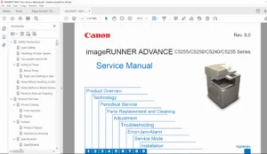
The Canon iPF8400S Service Manual PDF Download is an indispensable technical resource for servicing the Canon imagePROGRAF iPF8000 series large format printers, with specific focus on the iPF8400S model. This Canon large format printer troubleshooting guide provides comprehensive instructions on product description, technical reference, installation, disassembly/reassembly, maintenance, troubleshooting, service mode, and error codes, making it a key imagePROGRAF iPF8400S maintenance manual for professional repairs.
File Details:
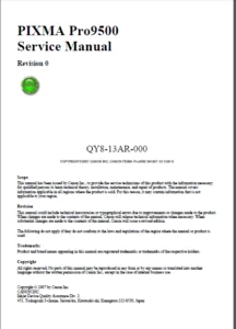
- Manual Name: Service Manual for iPF8000 Series iPF8400S
- Models Covered: iPF8000 series, iPF8400S
- Year: 2018
- Manual PDF Quality: High-quality scanned document
- No. of Pages: 312
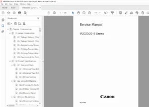
The manual emphasizes safety precautions, firmware operations, mechanical and electrical systems, and detailed detection functions. Below is the neatly categorized Table of Contents extracted from the manual:
- Chapter 1: Product Description
- 1.1 Product Overview
- 1.1.1 Product Overview
- 1.2 Features
- 1.2.1 Features
- 1.2.2 Printhead
- 1.2.3 Ink Tank
- 1.2.4 Cutter Unit
- 1.2.5 Roll Holder
- 1.2.6 Stand
- 1.2.7 Media Take-up Unit
- 1.2.8 Hard Disk Drive
- 1.2.9 Consumables
- 1.3 Product Specifications
- 1.3.1 Product Specifications
- 1.4 Detailed Specifications
- 1.4.1 Interface Specifications
- 1.5 Names and Functions of Components
- 1.5.1 Front
- 1.5.2 Rear
- 1.5.3 Top Cover (Inside)
- 1.5.4 Carriage
- 1.5.5 Ink Tank Cover (Inside)
- 1.6 Basic Operation
- 1.6.1 Operation Panel
- 1.6.2 Display
- 1.6.3 Main Menu
- 1.6.4 Basket Unit
- 1.7 Safety and Precautions
- 1.7.1 Safety Precautions
- 1.7.1.1 Moving Parts
- 1.7.1.2 Adhesion of Ink
- 1.7.1.3 Electric Parts
- 1.7.2 Other Precautions
- 1.7.2.1 Printhead
- 1.7.2.2 Ink Tank
- 1.7.2.3 Handling the Printer
- 1.7.3 Precautions When Servicing Printer
- 1.7.3.1 Notes on the Data Stored in the Printer
- 1.7.3.2 Confirming the Firmware Version
- 1.7.3.3 Precautions against Static Electricity
- 1.7.3.4 Precautions for Disassembly/Reassembly
- 1.7.3.5 Self-diagnostic Feature
- 1.7.3.6 Disposing of the Lithium Battery
- 1.7.1 Safety Precautions
- 1.1 Product Overview
- Chapter 2: Technical Reference
- 2.1 Basic Operation Outline
- 2.1.1 Printer Diagram
- 2.1.2 Print Signal Sequence
- 2.1.3 Print Driving
- 2.2 Firmware
- 2.2.1 Operation Sequence at Power-on
- 2.2.2 Operation Sequence at Power-off
- 2.2.3 Print Position Adjustment Function
- 2.2.4 Head Management
- 2.2.5 Printhead Overheating Protection Control
- 2.2.6 Pause between Pages
- 2.2.7 White Raster Skip
- 2.2.8 Sleep Mode
- 2.2.9 Hard Disk Drive
- 2.3 Printer Mechanical System
- 2.3.1 Outline
- 2.3.1.1 Outline
- 2.3.2 Ink Passage
- 2.3.2.1 Ink Passage
- 2.3.2.2 Ink Tank Unit
- 2.3.2.3 Carriage Unit
- 2.3.2.4 Printhead
- 2.3.2.5 Purge Unit
- 2.3.2.6 Maintenance Cartridge
- 2.3.2.7 Air Flow
- 2.3.3 Paper Path
- 2.3.3.1 Outline
- 2.3.3.2 Paper Path
- 2.3.3.3 Cutter Unit
- 2.3.1 Outline
- 2.4 Printer Electrical System
- 2.4.1 Outline
- 2.4.1.1 Overview
- 2.4.2 Main Controller
- 2.4.2.1 Main controller PCB components
- 2.4.3 Carriage Relay PCB
- 2.4.3.1 Carriage relay PCB components
- 2.4.4 Head Relay PCB
- 2.4.4.1 Head relay PCB components
- 2.4.5 Motor Driver
- 2.4.5.1 Media take-up PCB components
- 2.4.6 Maintenance Cartridge Relay PCB
- 2.4.6.1 Maintenance cartridge relay PCB components
- 2.4.7 Power Supply
- 2.4.7.1 Power supply block diagram
- 2.4.1 Outline
- 2.5 Detection Functions with Sensors
- 2.5.1 Covers
- 2.5.2 Ink passage system
- 2.5.3 Carriage system
- 2.5.4 Paper path system
- 2.5.5 Media take-up Unit
- 2.5.6 Others
- 2.1 Basic Operation Outline
- Chapter 3: Installation
- 3.1 Transporting the Printer
- 3.1.1 Transporting the Printer
- 3.1.1.1 Transporting the Printer
- 3.1.2 Reinstalling the Printer
- 3.1.2.1 Reinstalling the Printer
- 3.1.1 Transporting the Printer
- 3.1 Transporting the Printer
- Chapter 4: Disassembly/Reassembly
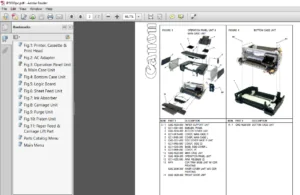
- 4.1 Service Parts
- 4.1.1 Service Parts
- 4.2 Disassembly/Reassembly
- 4.2.1 Disassembly/Reassembly
- 4.3 Points to Note on Disassembly and Reassembly
- 4.3.1 Note: Items that should never be disassembled
- 4.3.2 Moving the carriage manually
- 4.3.3 Units requiring draining of ink
- 4.3.4 External Covers
- 4.3.5 Drive Unit
- 4.3.6 Carriage Unit
- 4.3.7 Ink Tube Unit
- 4.3.8 Feeder Unit
- 4.3.9 Purge Unit
- 4.3.10 Ink Tank Unit
- 4.3.11 Linear Encoder
- 4.3.12 Head Management Sensor
- 4.3.13 PCBs
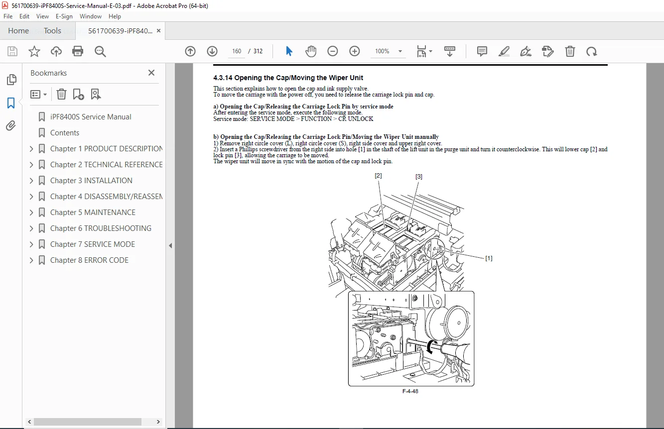
- 4.3.14 Opening the Cap/Moving the Wiper Unit
- 4.3.15 Opening and closing ink supply valves
- 4.3.16 Draining the ink
- 4.4 Applying the Grease
- 4.4.1 Applying the Grease
- 4.5 Adjustment and Setup Items
- 4.5.1 Adjustment Item List
- 4.5.2 Procedure after Replacing the Carriage Unit or Multi Sensor
- 4.5.3 Procedure after Replacing the Feed Roller or Feed Roller Encoder
- 4.5.4 Procedure after Replacing the Head Management Sensor
- 4.1 Service Parts
- Chapter 5: Maintenance
- 5.1 Periodic Replacement Parts
- 5.1.1 Periodic Replacement Parts
- 5.2 Consumable Parts
- 5.2.1 Consumable Parts
- 5.3 Periodic Maintenance
- 5.3.1 Periodic Maintenance
- 5.1 Periodic Replacement Parts
- Chapter 6: Troubleshooting
- 6.1 Troubleshooting
- 6.1.1 Outline
- 6.1.1.1 Outline of Troubleshooting
- 6.1.1 Outline
- 6.2 Location of Connectors and Pin Arrangement
- 6.2.1 Main controller PCB
- 6.2.2 Carriage relay PCB
- 6.2.3 Head relay PCB
- 6.3 Version Up
- 6.3.1 Firmware Update Tool
- 6.4 Service Tools
- 6.4.1 Tool List
- 6.1 Troubleshooting
- Chapter 7: Service Mode
- 7.1 Service Mode
- 7.1.1 Service Mode Operation
- 7.1.2 Map of the Service Mode
- 7.1.3 Details of Service Mode
- 7.1.4 e-Maintenance/imageWARE Remote
- 7.1.5 Viewing PRINT INF
- 7.2 Special Mode
- 7.2.1 Special Modes for Servicing
- 7.1 Service Mode
- Chapter 8: Error Code
- 8.1 Outline
- 8.1.1 Outline
- 8.2 Warning/Error/Service Call Error
- 8.2.1 Code Table
- 8.1 Outline
This iPF8400S schematic diagrams PDF and Canon printer parts list support thorough diagnostics and adjustments for optimal performance. No index is present in the manual, but the detailed TOC ensures easy navigation.
Empower your printing repairs today—download this Canon iPF8400S service manual PDF instantly and restore your large format printer to factory standards without delay!